Types of Electrical Diagrams
In accordance with ESKD (Unified System for Design Documentation) standards, diagrams are understood as graphical documents in which, using accepted symbols, the main elements or assembly nodes of a design are depicted, along with the connections joining them. According to the accepted classification, ten types of diagrams are distinguished, of which three are most commonly used in electrical engineering:
- Functional diagram, which shows the nodal elements (depicted as rectangles) along with the connecting lines linking them. A characteristic feature of this type of diagram is minimal detail. To describe the main functions of the nodes, the rectangles representing them are labeled with standard alphabetic designations. These can be various parts of a product distinguished by their functional purpose, for example, an automatic dimmer with a photorelay as a sensor, or an ordinary television set. An example of such a diagram is shown below.
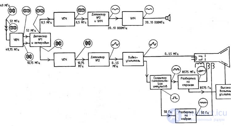 Example of a functional diagram of a television receiver
- Schematic (circuit) diagram. This type of graphical document shows in detail both the components used in the design and their connections and contacts. The electrical parameters of some components may be shown directly in the document, or presented separately in the form of a table.
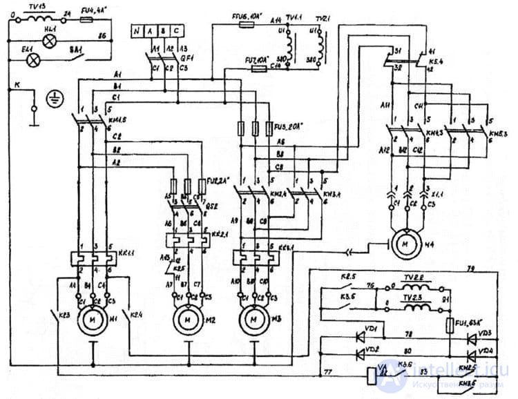 Example of a schematic diagram of a milling machine
If a diagram shows only the power section of an installation, it is called a single-line diagram; if all elements are shown, it is called a complete (full) diagram.
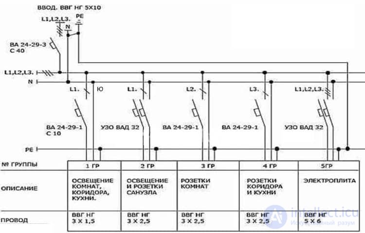 Example of a single-line diagram
- Wiring (installation) diagrams. These documents use positional designations of elements, that is, they indicate their location on the board, the method, and the sequence of installation.
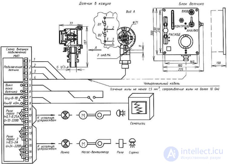 Wiring diagram of a stationary combustible-gas detector
If a drawing shows the wiring of an apartment, the locations of light fixtures, outlets, and other equipment are indicated on the floor plan. Such a document is sometimes referred to as a power-supply diagram; this is incorrect, since the latter shows the way consumers are connected to a substation or other power source.
Having dealt with electrical diagrams, we can now move on to the symbols used to denote the elements shown on them.
Graphical Symbols
Each type of graphical document has its own set of symbols, governed by the corresponding regulatory documents. As an example, let us present the basic graphical symbols for different types of electrical diagrams.
Examples of Graphic Symbols in Functional Diagrams
Below is a figure showing the main nodes of automation systems.
See also: What a drill bit is made of
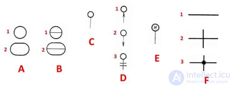 Examples of symbols for electrical devices and automation equipment in accordance with GOST 21.404-85
Description of the symbols:
- A – Basic (1) and permissible (2) representations of devices installed outside the electrical panel or junction box.
- B – The same as item A, except that the elements are located on the control panel or electrical panel.
- C – Representation of actuating mechanisms (AM).
- D – Effect of the AM on the control element (hereinafter CE) upon loss of power:
- The CE opens
- The CE closes
- The position of the CE remains unchanged.
- E – An AM additionally fitted with a manual drive. This symbol can be used for any of the CE positions specified in item D.
- F- Accepted representations of connection lines:
- General.
- No connection at the crossing point.
- Connection present at the crossing point.
Graphic Symbols in Single-Line and Complete Electrical Diagrams
There are several groups of graphical symbols for these diagrams; let us present the most common of them. For complete information, one should consult the relevant standards; the state standard numbers will be given for each group.
Power sources.
The symbols shown in the figure below are used to denote them.
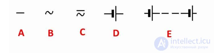 Graphical symbols of power sources on circuit diagrams (GOST 2.742-68 and GOST 2.750.68)
Description of the symbols:
- A – a DC voltage source; its polarity is denoted by the symbols «+» and «-».
- B – an electricity icon representing an AC voltage.
- C – the symbol for AC and DC voltage, used in cases where the device can be powered from either of these sources.
- D – representation of a rechargeable battery or galvanic power source.
- E - the symbol for a battery consisting of several cells.
Connection lines
The basic elements of electrical connectors are shown below.
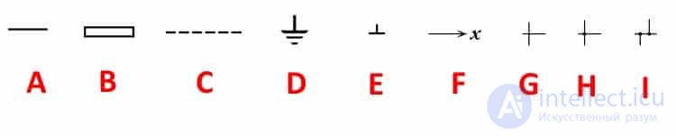 Symbols for connection lines on circuit diagrams (GOST 2.721-74 and GOST 2.751.73)
Description of the symbols:
- A – the general representation adopted for various types of electrical connections.
- B – a current-carrying or grounding bus.
- C – a shielding designation, which can be electrostatic (marked with the symbol «E») or electromagnetic («M»).
- D – the symbol for grounding.
- E – an electrical connection to the device chassis.
- F – in complex diagrams made up of several component parts, this is how a break in a connection is denoted; in such cases «X» is information about where the line will continue (usually the element number is indicated).
- G – a crossing with no connection.
- H – a connection at the point of crossing.
- I – branches.
Symbols for electromechanical devices and contact connections
Examples of symbols for magnetic starters, relays, and also the contacts of switching devices can be seen below.
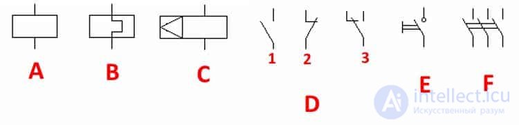 Graphical symbols adopted for electromechanical devices and contactors (GOST 2.756-76, 2.755-74, 2.755-87)
Description of the symbols:
- A – the symbol for the coil of an electromechanical device (relay, magnetic starter, etc.).
- B – the graphical symbol for the sensing element of thermal overload protection.
- C – representation of the coil of a device with mechanical interlocking.
- D – contacts of switching devices:
- Normally open (make).
- Normally closed (break).
- Changeover.
- E – the symbol for manual switches (buttons).
- F – a group switch (knife switch).
Graphical symbols of electrical machines
Let us give a few examples of representations of electrical machines (hereinafter EM) in accordance with the current standard.
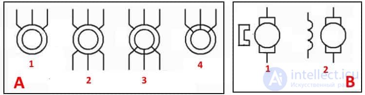 Symbols for electric motors and generators on circuit diagrams (GOST 2.722-68)
Description of the symbols:
- Asynchronous (squirrel-cage rotor).
- The same as item 1, but in a two-speed design.
- Asynchronous EMs with a wound rotor.
- Synchronous motors and generators.
- B – commutator machines, powered by direct current:
- EM with permanent-magnet excitation.
- EM with a field (excitation) winding.
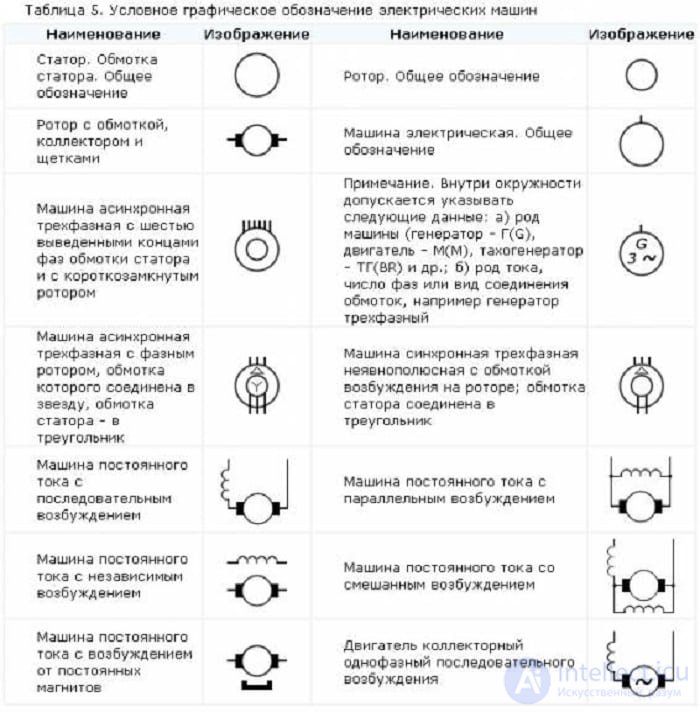 Symbols for electric motors on diagrams
Graphical symbols for transformers and chokes
Examples of graphical symbols for these devices can be found in the figure below.
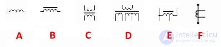 Correct symbols for transformers, inductors and chokes (GOST 2.723-78)
Description of the symbols:
- A – This graphic symbol can denote inductors (coils) or transformer windings.
- B – A choke (inductor) that has a ferrimagnetic core (magnetic circuit).
- C – Representation of a two-winding (two-coil) transformer.
- D – A device with three windings (coils).
- E – Symbol for an autotransformer.
- F – Graphic representation of a CT (current transformer).
Designation of measuring instruments and electronic components
A brief overview of the graphic symbols for these electronic components is shown below. Those who want to become more familiar with this information are recommended to review GOST 2.729-68 and 2.730-73.
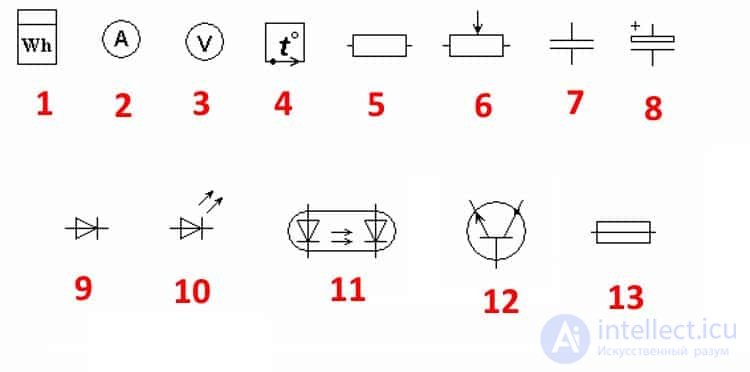 Examples of graphic symbols for electronic components and measuring instruments
Description of the symbols:
- Electricity meter.
- Representation of an ammeter.
- Instrument for measuring mains voltage.
- Temperature sensor.
- Fixed-value resistor.
- Variable resistor.
- Capacitor (general designation).
- Electrolytic capacitor.
- Diode symbol.
- LED (light-emitting diode).
- Representation of an optocoupler (diode type).
- Graphic symbol of a transistor (in this case, NPN).
- Fuse symbol.
Graphic symbols for lighting fixtures
Let us consider how electric lamps are represented on a schematic diagram.
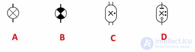 Example of how lamps are indicated on diagrams (GOST 2.732-68)
Description of the symbols:
- A – General representation of incandescent lamps (IL).
- B – An incandescent lamp used as an indicator.
- C – Standard symbol for discharge lamps.
- D – High-pressure discharge light source (the figure shows an example of a two-electrode design)
Designation of elements in a wiring installation diagram
To conclude the topic of graphic symbols, let us give examples of how sockets and switches are represented.
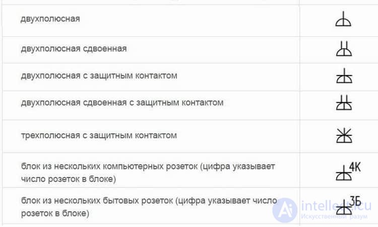 Example of how flush-mounted sockets are shown on wiring diagrams
How other types of sockets are depicted can easily be found in the regulatory documents available online.
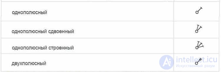 Symbol for flush-mounted switches
 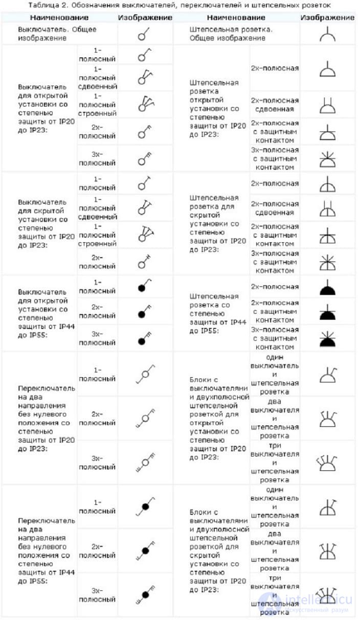 Symbols for sockets and switches
Letter designations
In electrical diagrams, in addition to graphic symbols, letter designations are also used, since without them reading the drawings would be quite problematic. Alphanumeric marking, just like graphic symbols, is regulated by normative documents; for electrical engineering this is GOST 7624-55
See also
- [[b6229]]
- [[b6228]]
- [[b9865]]
See also


Comments