
Lecture
Establishing AC coupling is necessary in order to prevent DC current from flowing between certain points in a circuit while still allowing AC current to pass freely. Electronic components that provide AC coupling, such as capacitors or transformers, are usually installed at the input and output of an amplifier. In this way, the specified quiescent (static) operating point of the transistor is not affected by the static operating points of the preceding and following stages.
In the circuit shown in Fig. 23.1, the capacitor couples points A and B for AC current, while R is the load resistor. For DC current, the capacitor acts as an open circuit, completely blocking the flow of DC current between points A and B. For this reason, the coupling capacitor is called a blocking or coupling capacitor.
Satisfactory AC coupling quality is achieved only when the reactive capacitance Xc of the capacitor at the operating frequency is much smaller than the resistance of the load resistor R. In that case, only a very small fraction of the input signal voltage is dropped (and lost) across this capacitor. For example, if Vin = 100 mV, then the AC coupling can be considered satisfactory when the output voltage Vout = 95 mV and 5 mV (5%) is dropped across the coupling capacitor. The required capacitance of the coupling capacitor is determined by two factors.
1. Resistance of the load resistor R. Assuming that satisfactory AC coupling is achieved when Xc = R/20, for R = 1 kΩ we get Xc = 50 Ω.
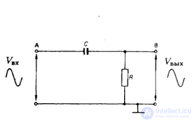
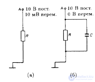
Fig. 23.1. Installation of the coupling Fig. 23.2. Effect of the decoupling capacitor. capacitor.
The potentials at point A are shown without a decoupling capacitor (a) and with a decoupling capacitor (b).
Assume that the operating frequency f = 300 Hz. Since Xc = 1/2πfC1, then
If the resistance of the load resistor is increased to 100 kΩ, then Xc= R/20 = 1/20·100 = 5 kΩ
Thus, if the resistance of the load resistor is increased by a factor of 100 (from 1 kΩ to 100 kΩ), the capacitance of the coupling capacitor can be reduced in the same proportion (from 10 µF to 0.1 µF).
In general, the greater the resistance of the load resistor, the smaller the required capacitance of the coupling capacitor.
2. Operating frequency. Let us take as our starting point the example given above, where satisfactory AC coupling was achieved with C = 10 µF and R = 1 kΩ for f = 300 Hz.
If the operating frequency is now increased to 300 kHz, then taking into account the condition Xc = R/20 = 50 Ω, we obtain
Thus, if the operating frequency is increased by a factor of 1000 (from 300 Hz to 300 kHz), the capacitance of the coupling capacitor can be reduced by a factor of 1000 (from 10 µF to 0.01 µF).
In general, for a given load-resistor resistance, low operating frequencies require the use of coupling capacitors with large capacitance, and vice versa.
When it comes to an operating frequency range, the capacitance of the coupling capacitor is determined by the lowest frequency in that range. Referring back to the examples considered above, we see that a capacitor with a capacitance of 10 µF, according to the calculations, provides adequate AC coupling at a frequency of 300 Hz and even more so at a frequency of 300 kHz. On the other hand, a capacitor with a capacitance of 0.1 µF provides adequate coupling at a frequency of 300 kHz, but is unsuitable for AC coupling at a frequency of 300 Hz.
Decoupling
Fig. 23.2(b) shows capacitor C. providing decoupling for resistor R. Without the capacitor (Fig. 23.2(a)), the DC potential at point A is 10 V, while the AC signal potential is 10 mV. The capacitor, which represents an open circuit for DC current, has no effect on the DC potential at point A. However, if the capacitance of this capacitor is such that at the operating frequency its reactive impedance is significantly smaller than the resistance of resistor R, the capacitor will effectively short the AC signal to ground. Thus, the AC potential at point A will become zero. The capacitance of capacitor C, providing satisfactory decoupling, is determined by the resistance of resistor R and the operating frequency — using the same formulas that were used to calculate the capacitance of the coupling capacitor.
Amplifier with RC Coupling
Fig. 23.3 shows the circuit of an amplifier with RC coupling, where C1 — is the input coupling capacitor. The capacitance of this capacitor must be comparatively large due to the low input resistance of the transistor in a common-emitter (CE) circuit (this resistance becomes even smaller due to the shunting effect of resistor R1. at the amplifier input). Capacitor C2 couples the amplifier output to the load or the next stage; its capacitance is comparable to the capacitance of capacitor C1. Typical values for coupling-capacitor capacitances are as follows:
for audio frequencies:10-50 µF.
for radio frequencies:0.01-0.1 µF.
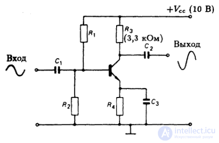
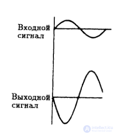
Fig. 23.3. Amplifier with RC coupling and decoupling capacitor C3 in the emitter circuit.
Fig. 23.4. Inversion (180° phase shift) of the signal in a common-emitter (CE) amplifier.
Negative feedback through resistor R4 in the amplifier of Fig. 23.3, on the one hand, provides the necessary DC stability for the amplifier, while on the other hand, it reduces its gain to a very small value (2-3). The reduction in gain is due to the action of negative AC feedback caused by the signal voltage drop across resistor R4. To eliminate this negative AC feedback while simultaneously preserving DC stability, an emitter decoupling capacitor C3 is used.
Typical values for the capacitance of the emitter decoupling capacitor are of the same order as those for the coupling capacitor.
Gain
The circuit shown in Fig. 23.3 is a complete single-stage common-emitter (CE) amplifier circuit. When a signal is applied (for example, of sinusoidal shape) to the amplifier input, this signal is passed through capacitor C1 to the base of the transistor. At the beginning of the positive half-cycle of the input signal, the base potential rises relative to the emitter potential, the voltage VBEincreases, the emitter current Ie, and with it the collector current Ic, increase, and as a result the voltage at the collector Vc. decreases. This means that the positive half-cycle of the input signal corresponds to a negative half-cycle of the output signal. Conversely, the negative half-cycle of the input signal corresponds to a positive half-cycle of the change in collector voltage. Thus, the signals at the input and output of the amplifier are in antiphase, as shown in Fig. 23.4. Signal amplification occurs because a very small swing in voltage VBEproduces a large swing in transistor current, which, flowing through resistorR3 , causes a large collector-voltage swing.
Load line
The output characteristics of a transistor give a general idea of how the transistor operates. To get an idea of how the transistor works in a specific circuit, a load line must be drawn. Fig. 23.5 shows the family of output characteristics of the transistor operating in the amplifier circuit of Fig. 23.3, together with load line XY.
Before drawing the load line, first fix two points lying on this line. It is best to use point X on the x axis, where current Ic = 0, and point Y on the y axis, where Vc = 0. A straight line — the load line — is drawn through these two points. It is assumed that Vc = VCE.
Point X. At this point the transistor current Ic = 0. The transistor is in the cutoff state. Consequently, the collector voltage Vc = VCC.
Point Y. Here the collector voltage Vc = 0. Substituting Vc = 0 into the equation VCC = Vc + VR3, we get VCC = VR3. But VR3 = Ic R3, therefore VCC = Ic R3. Consequently,
Ic = VCC / R3.
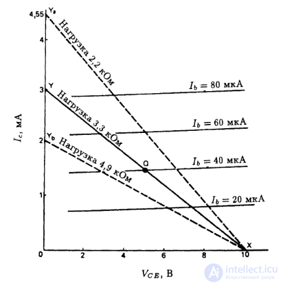
Fig. 23.5. Load line.
For the values shown in Fig. 23.3, the positions of points X and Y are determined by the following parameters:
Point X: Ic = 0, Vc = VCC = 10 V.
Point Y: Vc = 0, Ic = VCC/ R3 = 10/3.3 = 3 mA.
Thus, XY is the load line for a load resistor with resistance R3 = 3.3 kΩ.
Using a load resistor of a lower rating (2.2 kΩ), we get load line XYa. The position of point X does not change compared with the previous case, since the voltage VCC remains the same — 10 V. For point Yb we get Ic = VCC / R3 = 10 V/2.2 kΩ = 4.55 mA.
A load resistor of a higher rating, for example 4.9 kΩ, corresponds to load line XYb with point Yb at Ic = 10 V/4.9 kΩ ≈ 2 mA.
Graphical analysis
The process of signal amplification takes place along the load line and can be represented graphically, as shown in Fig. 23.6. Point Q is the static operating point, representing the amplifier's DC operating mode, i.e. in the absence of a signal. The operating point sets the transistor's bias in the static mode. In the case under consideration, the bias is determined by the following values:
Ib = 20 µA, Ic = 1.5 mA, Vc = 5 V.
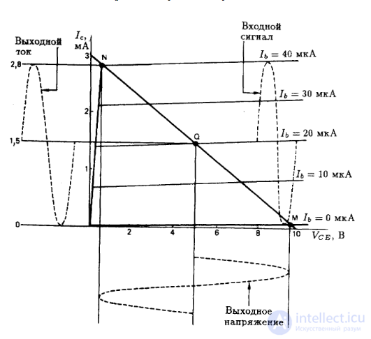
Fig. 23.6. Graphical representation of the amplifier's operation.
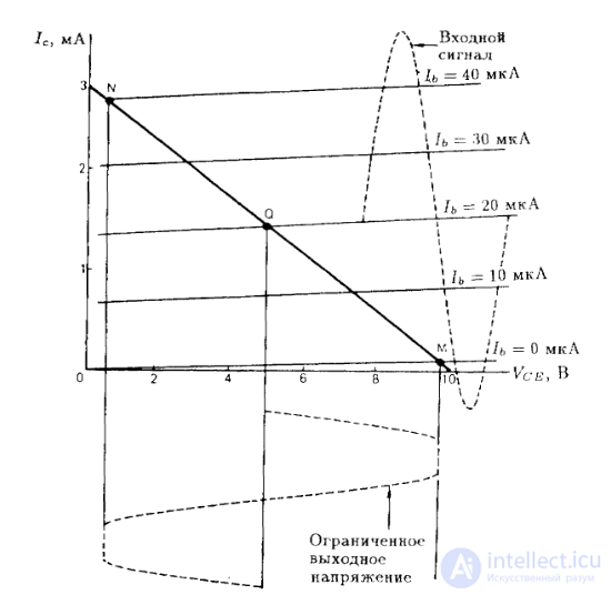
Fig. 23.7. Amplifier overload leading to clipping of the output signal.
When a signal is applied, the base current varies sinusoidally with an amplitude of 20 µA (from 0 to 40 µA). This causes the collector current Ic to change with a swing of 2.8 mA and the collector voltage to change with a swing of about 9 V.
On one side, the swing of the input signal is limited by the line Ib = 0, corresponding to the transistor's cutoff (point M on the load line), and on the other side – by the line Ib = 40 µA, corresponding to the transistor's saturation (point N on the load line). For the amplifier under consideration, the operating point Q is chosen in the middle of the load line. In this case, when a signal with an amplitude of 20 µA is applied to the transistor's base, the base current varies within the range from 0 to 40 µA, providing the maximum value of undistorted output signal.
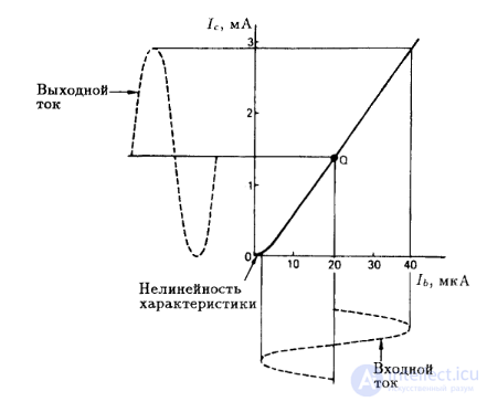
Fig. 23.8. Graphical representation of amplifier operation using the transfer characteristic.
Any attempt to exceed this input signal level leads to distortion of the output signal waveform. This is clearly seen in Fig. 23.7, which illustrates the case of amplifier overload with resulting clipping of the sinusoidal signal. The input and output signals can also be represented graphically by means of the transistor's transfer characteristic (Fig. 23.8). The amplifier's operating range is limited by the linear portion of the transfer characteristic; going beyond the boundaries of this portion leads to distortion.
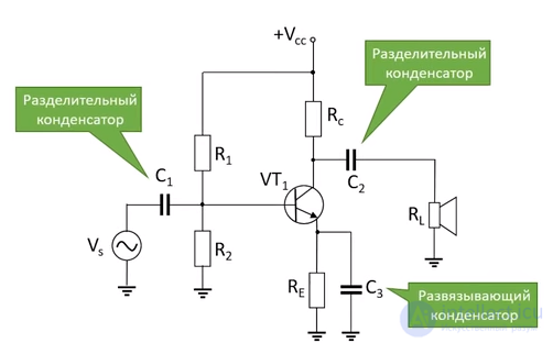
When AC coupling must be established between certain points or blocks of a circuit while blocking the flow of DC current, electronic components that provide coupling only for AC are used – for example, capacitors or transformers.
When it comes to amplifier stages, such capacitors are commonly called blocking (bypass) or coupling capacitors.
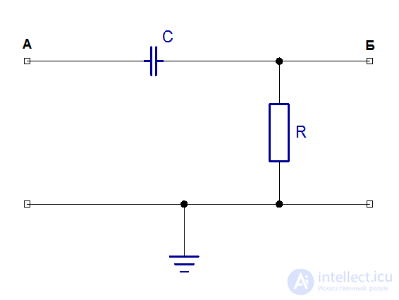
Fig. 1. Use of a coupling capacitor
In the circuit shown in Fig. 1, the capacitor couples points A and B by AC. R is the load resistance. For DC, the capacitor acts as an open circuit, completely blocking the flow of DC current between points A and B. In a real circuit, the role of the load resistor is played by the next amplification stage.
In this circuit, capacitor C and resistor R form the simplest high-pass filter (HPF).
The cutoff frequency of a filter is the frequency at which the signal attenuation reaches -3 dB (on a logarithmic scale), or equals 1/√2 (≈0.71) on a linear scale. That is, the signal amplitude at the cutoff frequency is ≈71% of the input value. The cutoff frequency of an RC filter is calculated using the formula:
f = 1 / (2 ⋅ π ⋅ R ⋅ C)
For AC, the filter itself can be represented as the simplest voltage divider, in which the ratio of resistances depends on frequency; here the reactance of the capacitor Xc is calculated using the following formula:
Xc = 1 / (2 ⋅ π ⋅ f ⋅ C)
Also, when calculating this capacitor it must be kept in mind that satisfactory AC coupling quality is achieved only when the reactance Xc of the capacitor at the operating frequency is much smaller than the load resistance R – in that case only a very small fraction of the input signal voltage is dropped (and lost) across this capacitor.
From the formulas for cutoff frequency and reactance, it is evident that the required capacitance of the coupling capacitor is determined by two factors:
For approximate calculations, satisfactory AC coupling can be considered achieved when Xc = R/20.
At R = 1 kΩ we get Xc = 50 Ω. Suppose the operating frequency is f = 300 Hz.
Since Xc = 1 / (2 ⋅ π ⋅ f ⋅ C), then
C = 1 / 94247.78 = 10.61 (µF)
From the above, two basic rules follow:
The greater the load resistance, the smaller the required capacitance of the coupling capacitor.
For a given load resistance, lower operating frequencies require coupling capacitors of larger capacitance, and vice versa.
If, on the other hand, we are talking about an operating frequency range, the capacitance of the coupling capacitor is determined by the lowest frequency in that range. According to the calculations, it is clear that a capacitor with a capacitance of 10 µF provides adequate AC coupling at a frequency of 300 Hz, and even more so at a frequency of 300 kHz. On the other hand, a capacitor with a capacitance of 0.1 µF provides adequate coupling at a frequency of 300 kHz, but is unsuitable for AC coupling at a frequency of 300 Hz.
One way of using a capacitor in the circuit design of amplifier stages is to connect the capacitor into the transistor's thermal-stabilization circuit, in parallel with a resistor. In this case, this capacitor is conventionally referred to as a "decoupling" capacitor.
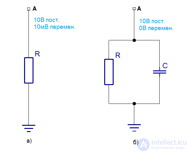
Fig. 2. Effect of the decoupling capacitor.
Fig. 2.6 shows capacitor C, providing decoupling of resistor R with respect to AC current. Without the capacitor (Fig. 2.a), the DC potential at point A is 10 V, while the AC signal potential is 10 mV. The capacitor, representing an open circuit for DC current, has no effect on the DC potential at point A. However, if the capacitance of this capacitor is such that at the operating frequency its reactive impedance is significantly smaller than the resistance of resistor R, the capacitor will effectively short-circuit the AC signal to ground. Thus, the AC potential at point A becomes zero.
The capacitance of capacitor C, providing satisfactory decoupling, is determined by the resistance of resistor R and the operating frequency — using the same formulas that were used to calculate the capacitance of the coupling capacitor.
One example of using a decoupling capacitor is an amplifier stage built on the classic common-emitter circuit with negative feedback (NFB).
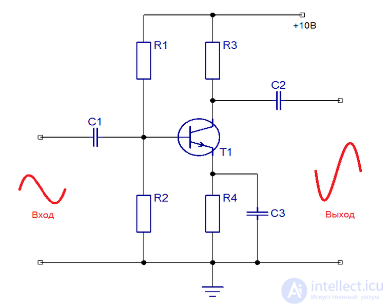
Fig. 3. Amplifier with a decoupling capacitor in the emitter circuit.
Fig. 3 shows the circuit of an amplifier built on the classic common-emitter (CE) circuit. Here C1 — is the input coupling capacitor. The capacitance of this capacitor must be comparatively large due to the low input resistance of the transistor in a CE circuit (for detailed component-value calculations, see the article "Calculating a Common-Emitter Amplifier Stage"). Capacitor C2 couples the amplifier output to the load or the next stage; its capacitance is comparable to the capacitance of capacitor C1.
Negative feedback through resistor R4 in this amplifier, on the one hand, provides the necessary DC stability for the amplifier, while on the other hand it reduces its gain to a very small value (2-3). To eliminate the negative AC feedback while simultaneously preserving DC stability, an emitter decoupling capacitor C3 is used. In addition, this RC circuit in the emitter path provides thermal stabilization for this amplifier stage.
Typical values for the capacitance of the emitter decoupling capacitor are of the same order as those for the coupling capacitor.
An RC circuit is an electrical circuit consisting of a capacitor and a resistor. It can be regarded as a voltage divider with one of its arms having capacitive reactance to AC current.
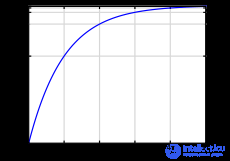
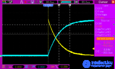
If the input signal is applied to Vin , while the output is taken from Vc (see figure), then such a circuit is called an integrating-type circuit.
The response of an integrating-type circuit to a unit step input with amplitude V is given by the following formula:

Thus, the time constant τ of this aperiodic process will be equal to

Integrating circuits pass the DC component of a signal while cutting off high frequencies, that is, they act as low-pass filters. In this case, the higher the time constant  , the lower the cutoff frequency. In the limit, only the DC component will pass through. This property is used in secondary power supplies, where it is necessary to filter out the AC component of the mains voltage. A cable made of a pair of wires exhibits integrating properties, since any wire is a resistor possessing its own resistance, and a pair of wires running close together also forms a capacitor, albeit with a small capacitance. When signals pass through such a cable, their high-frequency component can be lost, and increasingly so the longer the cable.
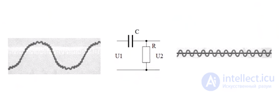
A differentiating RC circuit is obtained by swapping the resistor R and the capacitor C in the integrating circuit. Here the input signal is applied to the capacitor, and the output is taken from the resistor. For a DC voltage, the capacitor represents an open circuit, meaning that the DC component of the signal in a differentiating-type circuit will be blocked. Such circuits act as high-pass filters. The cutoff frequency in them is determined by the same time constant . The larger is, the lower the frequency that can pass through the circuit unchanged.
Differentiating circuits have another distinctive feature. At the output of such a circuit, a single signal is converted into two consecutive voltage jumps, up and down relative to the baseline, with an amplitude equal to the input voltage. The baseline is either the positive terminal of the source or "ground", depending on where the resistor is connected. When the resistor is connected to the source, the amplitude of the positive output pulse will be twice the supply voltage. This is used for voltage multiplication, and also, when the resistor is connected to "ground", for generating a bipolar voltage from an available unipolar one.
High-pass filter
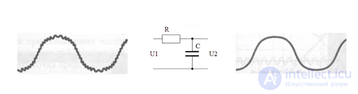
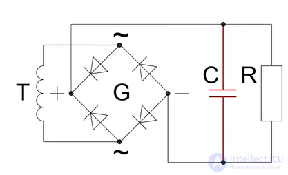
To smooth the ripple of a DC voltage, a smoothing capacitor connected in parallel with the load is often used as a filter. As the voltage rises along the sinusoidal curve, not only is the load supplied, but the capacitor is also charged. After the voltage reaches its maximum (peak) value, it begins to fall. At this point, while the voltage at the rectifier output is falling, the capacitor begins to discharge into the load, thereby helping to maintain the voltage across it to some extent. This is how the ripple of the voltage at the rectifier output is smoothed.
As examples, let us consider basic rectifier circuits. In Figure 1, the top diagram shows the supply mains voltage. Below is shown the circuit of a single-phase half-wave rectifier and the corresponding diagram of the rectified voltage across the load. At the bottom is the rectifier circuit with a capacitive filter C1 and the corresponding diagram of the rectified voltage across the load.
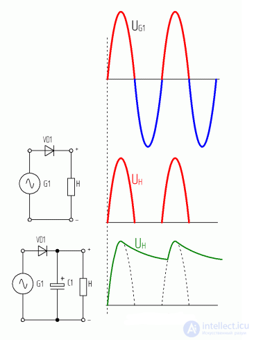
Figure 1. Operation of a capacitive filter in single-phase half-wave rectification.
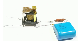
To protect relay contacts from arcing when powering an AC load, a snubber (damper) is needed, consisting of a resistor and a capacitor connected in series. This circuit reduces the rate of voltage rise and suppresses the high-voltage pulse. The chain works on alternating current, and the component parameters are calculated accordingly. When powering a 230 volt inductive load, the resistor is usually set to 220 Ω and the capacitor to up to 0.47 µF. When powering 13 volts, the capacitance of the capacitor was set to 1 µF and the resistor to 1 Ω. The arc during switching was successfully suppressed. It should be taken into account that a small current will flow through the snubber to the load if it is connected in parallel with the relay contacts. The snubber is also connected in parallel with the load; in that case no current will flow through the load when the contacts are open, but it is unknown how the snubber may affect the inductive load in that case.
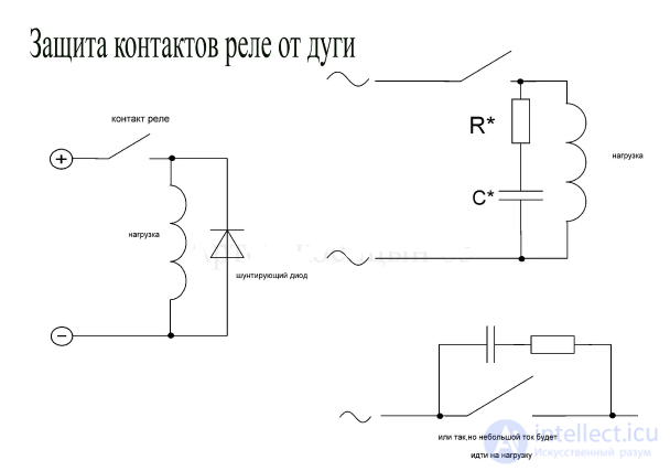
a protective diode must not be placed across the coil when powering with alternating current.
A three-phase induction motor needs to be connected as a capacitor motor using the following classic circuits.
Once again, I remind you that these are the most common circuits for connecting a three-phase motor to a single-phase network. There are several other methods of connection, but we will not discuss them in this article.
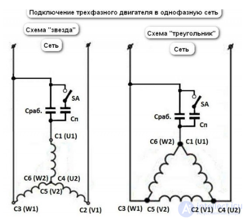
As can be seen from the circuits, this is achieved using the running and starting capacitors. They are also called phase-shifting capacitors.
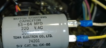
phase-shifting capacitor for connecting a three-phase motor to a single-phase network.
Capacitors with an oxide dielectric (formerly called electrolytic) are used as running and starting capacitors. Running and starting capacitors for induction motors are connected to an AC network, and they must be non-polarized. They have a comparatively high rated voltage of 450 volts for oxide capacitors, which is twice the mains voltage. In practice, capacitors with capacitances on the order of tens and hundreds of microfarads are used. As mentioned above, the running capacitor is used to produce a rotating magnetic field. The starting capacitance, on the other hand, is used to produce the magnetic field needed to increase the motor's starting torque. The starting capacitor is connected in parallel with the running capacitor through a centrifugal switch. When the starting capacitance is present, the rotating magnetic field of the induction motor at the moment of starting approaches a circular one, and the magnetic flux increases. This increases the starting torque and improves the motor's characteristics. When the induction motor reaches a speed sufficient to disengage the centrifugal switch, the starting capacitance is disconnected and the motor continues to operate only with the running capacitor. The circuit for connecting the running and starting capacitors is shown in (Fig. 1).
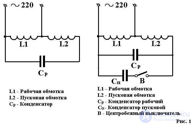
Circuit with running and starting capacitors
The table below shows separate characteristics of running and starting capacitors for induction motors.
|
|
RUNNING |
STARTING |
| Purpose | For induction motors | For asynchronous motors |
| Connection diagram | In series with the motor's starting winding | In parallel with the running capacitor |
| As a | Phase-shifting element | Phase-shifting element |
| Purpose | To produce a rotating (circular) magnetic field required for the motor to operate | To produce a magnetic field required to increase the motor's starting torque |
| Time of activation | During motor operation | At the moment the motor starts |
Traditionally, in switching converters, the transistor's drain circuit includes the inductance of the transformer's or choke's primary winding. And when the transistor turns off abruptly, under conditions where the switched current has not yet dropped to a safe value, according to the law of electromagnetic induction a high voltage arises on the winding, proportional to the winding's inductance and to the speed at which the transistor transitions from the conducting state to the off state.
If the edge in this case is sufficiently steep, and the total inductance of the winding in the transistor's drain circuit is significant, then the high rate of rise of the drain-source voltage will instantly lead to catastrophic failure. To reduce this rate of voltage rise and ease the thermal conditions of transistor turn-off — an RCD snubber is placed between the drain and source of the protected switch.
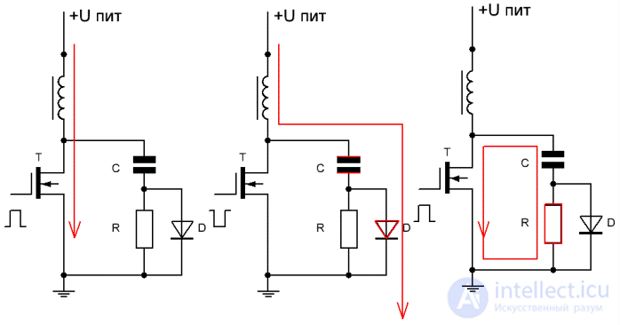
The RCD snubber works as follows. At the moment the transistor turns off, the current in the primary winding, due to its inductance, cannot drop to zero instantly. And instead of burning out the transistor, the charge, driven by the high EMF, rushes through diode D into capacitor C of the snubber circuit, charging it, while the transistor turns off gently, with only a small current flowing through its junction.
When the transistor starts to turn on again (switching abruptly to the conducting state to handle the next switching period), the snubber capacitor begins to discharge, but now not through the bare transistor but through the snubber resistor R. And since the resistance of the snubber resistor is several times greater than the resistance of the drain-source junction, most of the energy stored in the capacitor is dissipated in the resistor rather than in the transistor. Thus the RCD snubber absorbs and dissipates the energy of the parasitic high-voltage spike from the inductance.
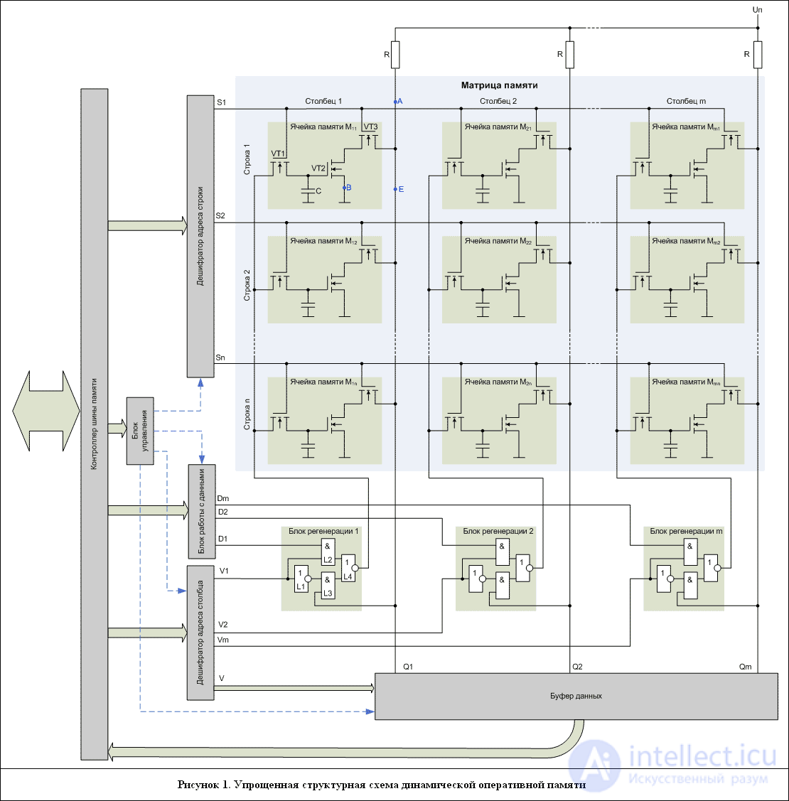
As can be seen from the figure, the main memory block is the memory array, consisting of a large number of cells, each of which stores 1 bit of information.
Each cell consists of one capacitor (C) and three transistors. Transistor VT1 enables or disables writing new data or refreshing the cell. Transistor VT3 acts as a switch that keeps the capacitor from discharging and enables or disables reading data from the memory cell. Transistor VT2 is used to read data from the capacitor. If the capacitor is charged, transistor VT2 is on, and current flows along line AB; accordingly, there will be no current at output Q1, which means the cell stores a bit of information with a value of zero. If the capacitor has no charge, transistor VT2 is off, and current flows along line AE; accordingly, there will be current at output Q1, which means the cell stores a bit of information with the value “one”.
The charge on the capacitor, used to keep transistor VT2 in the on state while current flows through it, is quickly depleted, so when reading data from a cell it is necessary to refresh (regenerate) the capacitor's charge.
For dynamic memory to operate, a voltage must always be applied to the array; in the diagram it is denoted as Up. Through resistors R, the supply voltage Up is distributed evenly among all the columns of the array.
The memory also includes a memory bus controller, which receives commands, address, and data from external devices and relays them to the internal memory blocks.
Commands are passed to the control unit, which organizes the operation of the other blocks and the periodic refresh of the memory cells.
The address is split into two components – the row address and the column address, and passed to the corresponding decoders.
The row address decoder determines which row a read or write should be performed on, and applies a voltage to that row.
During a read, the column address decoder determines which of the read data bits were requested and must be output to the memory bus. During a write, the decoder determines which columns should receive write commands.
The data-handling block determines which data must be written into which memory cell, and outputs the corresponding data bits for writing into those cells.
The refresh blocks determine:
The data buffer stores the entire row of the array that was read, since a read always reads the whole row at once, and later allows the required data bits to be selected from the row that was read.
Let us consider the operating principle of dynamic memory using the example of the block diagram shown in Figure 1. We will consider the operation of the first cell (M11). The operation of the other memory cells is exactly identical.
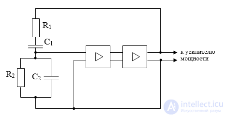
Figure – Diagram of the simplest RC oscillator
An RC-type master oscillator is a two-stage resistor amplifier with positive feedback. This feedback is provided by means of a divider having two arms: one arm is formed by a series connection of capacitor C1 with resistance R1, the other – by a parallel connection of capacitor C2 with resistance R2.
The frequency of RC-type oscillators is determined from the formula:
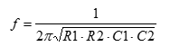
As a rule, the parameters R1 and R2, as well as C1 and C2, are chosen to be equal:
R1 = R2 = R;
C1 = C2 = C.
Then the formula takes the form:

In RC oscillators, the frequency is determined by the values of the resistances and capacitances included in the positive feedback loop, which is necessary for generating oscillations.
By changing one of the values R (or C), the range of generated frequencies is changed (step adjustment), while changing the other value C (or R) produces a smooth change of frequency within the subrange.
Positive feedback provides for the generation of oscillations at a specific frequency, while negative feedback stabilizes the oscillator's operation across the entire range of generated frequencies.
RC-type oscillators have a simple circuit and good quality characteristics, which is why they have become widely used.
An oscillatory circuit is an electrical circuit containing an inductor, a capacitor, and a source of electrical energy. When the circuit elements are connected in series, the oscillatory circuit is called a series circuit; when connected in parallel — a parallel circuit.
An oscillating circuit — the simplest system in which free electromagnetic oscillations can occur.
The resonant frequency of the circuit is determined by the so-called Thomson formula:
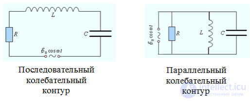
An oscillating circuit (o.c.) is a circuit consisting of a capacitor and an inductor. Under certain conditions, electromagnetic oscillations of charge, current, voltage and energy can arise in the o.c.
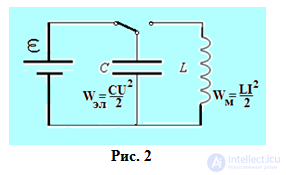
Consider the circuit shown in Fig. 2. If the switch is set to position 1, the capacitor will charge and a charge Q and voltage UC will appear on its plates. If the switch is then moved to position 2, the capacitor will begin to discharge, current will flow in the circuit, and the energy of the electric field contained between the capacitor plates will be converted into the energy of the magnetic field concentrated in the inductor L. The presence of the inductor causes the current in the circuit to increase not instantaneously but gradually, due to the phenomenon of self-induction. As the capacitor discharges, the charge on its plates will decrease and the current in the circuit will increase. The loop current will reach its maximum value when the charge on the plates is zero. From this moment, the loop current will begin to decrease, but, owing to self-induction, it will be sustained by the magnetic field of the inductor, i.e., when the capacitor is fully discharged, the energy of the magnetic field stored in the inductor will begin to convert into the energy of the electric field. Due to the loop current, the capacitor will begin to recharge, and a charge opposite to the original one will begin to accumulate on its plates. The recharging of the capacitor will continue until all the energy of the inductor's magnetic field has converted into the energy of the capacitor's electric field. The process will then repeat in the opposite direction, and thus electromagnetic oscillations will arise in the circuit.
Let us write Kirchhoff's 2nd law for the o.c. under consideration,
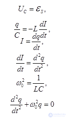
- differential equation of the o.c.
We have obtained the differential equation of charge oscillations in the o.c. This equation is analogous to the differential equation describing the motion of a body under a quasi-elastic force. Consequently, the solution to this equation will be written in an analogous way
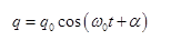
- equation of charge oscillations in the o.c.
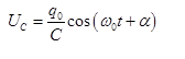
- equation of voltage oscillations across the capacitor plates in the o.c.
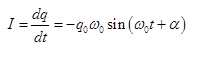
- equation of current oscillations in the o.c.
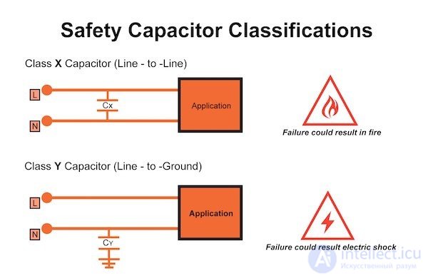
Types X and Y capacitors
X and Y interference suppression capacitors are used in mains voltage filtering to reduce EMI. However, they are connected directly to hazardous mains voltage, which requires them to be safety certified. There are various form factors of interference suppression capacitors used in filter circuits, taking safety requirements into account. Surface-mount ceramic capacitors and ceramic disc capacitors are usually used to suppress mains interference, while film capacitors are more often used to attenuate induced interference.
Ceramic and film capacitors can be used as both X and Y capacitors, but their characteristics and form factor may be more suitable for one or the other type of application. Ceramic capacitors are more often used to suppress interference in switch-mode power supplies and inverters, in high-frequency switching lines for motor control, relays and inverters. Film capacitors – where their self-healing properties are in demand, for example, in capacitive power supplies, electricity meters, transportation, and harsh operating conditions.
The inductor and the capacitor are two key components in circuit design that perform different functions depending on the task of the circuit. Here are a few tips on their application:
High-frequency noise filtering: Inductors effectively suppress high-frequency noise in power circuits. They are used in filters to smooth ripple and suppress interference.
Inductive load: In circuits where energy needs to be stored in a magnetic field, for example in switch-mode power supplies (DC-DC converters), inductors are often used as energy storage elements.
Current smoothing: In pulsed circuits, a coil helps smooth out current fluctuations because it resists sudden changes in current.
Resonant circuits: In radio-frequency and resonant circuits, coils create resonance together with capacitors. This is important for tuning resonant frequencies.
Chokes: Coils are used as chokes to limit currents in certain parts of a circuit.
Low-frequency noise filtering: Capacitors are good at filtering low-frequency interference and ripple. They are used in power supplies to smooth out voltage.
Energy buffer: Capacitors can store and release energy, which makes them useful for short-term energy storage, for example in switching power supply circuits and regulators.
Signal decoupling: In signal circuits, capacitors are often used for decoupling or blocking the DC component, allowing only AC signals to pass (for example, in AC-coupling circuits).
Resonant circuits: Capacitors, together with inductors, create LC resonant circuits, which are important for tuning frequency in radio-frequency circuits and filters.
Phase-shifting circuits: In synchronization and phase-shift circuits, capacitors help change the phase of a signal, which is used in phase-shift oscillators and filters.
The correct choice between an inductor and a capacitor depends on the nature of the signal to be filtered or converted, and on the desired effect on current and voltage.
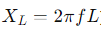
Inductors and capacitors have opposite effects on electrical circuits, since their response to varying signals and their interaction with current and voltage differ. Here is a comparison of their main effects:
 .
.| Parameter | Inductance | Capacitor |
|---|---|---|
| Energy storage | In the magnetic field | In the electric field |
| Response to alternating current | Resists change in current, blocks high frequencies | Resists change in voltage, passes high frequencies |
| Filtering | Blocks high-frequency interference | Blocks low-frequency signals |
| Effect on |
продолжение следует...
Часть 1 Applications of Capacitors: RC Networks, Coupling and Decoupling, Smoothing, Snubber, Phase-Shifting, Run and Start, X
Часть 2 See also - Applications of Capacitors: RC Networks, Coupling and

Comments