
Lecture
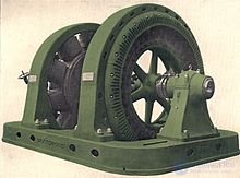
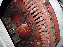
A synchronous motor-generator that was used
as a rectifier (1909)
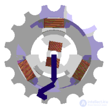
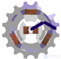
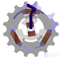
A synchronous electric motor— is an AC electric motor whose rotor speed equals the rotation speed of the magnetic field in the air gap.
The main parts of a synchronous machine are the armature and the inductor (field winding). As a rule, the armature is located on the stator, while the inductor is located on the rotor, separated from it by an air gap — thus, in terms of operating principle, a synchronous machine is, as it were, a DC machine «turned inside out», in which the alternating current for the armature winding is not obtained by means of a commutator, but is supplied from outside.
The armature is one or more AC windings. In motors, the currents fed into the armature create a rotating magnetic field, which couples with the inductor's field, and thus energy conversion takes place. The armature field acts on the inductor field and is therefore also called the armature reaction field. In generators, the armature reaction field is created by the alternating currents induced in the armature winding by the inductor.
The inductor consists of poles — DC electromagnets or permanent magnets (in micromachines). The inductors of synchronous machines have two different designs: salient-pole or non-salient-pole. A salient-pole machine is distinguished by the fact that the poles are clearly pronounced and have a design similar to the poles of a DC machine. In a non-salient-pole design, the field winding is laid in the slots of the inductor core, very similar to the winding of the rotors of wound-rotor induction machines, with the only difference being that a space not filled with conductors is left between the poles (the so-called large tooth). Non-salient-pole designs are used in high-speed machines to reduce the mechanical load on the poles.
To reduce the magnetic reluctance, that is, to improve the passage of the magnetic flux, ferromagnetic cores are used for the rotor and stator. They are mainly a laminated construction (built up from individual sheets) of electrical steel.
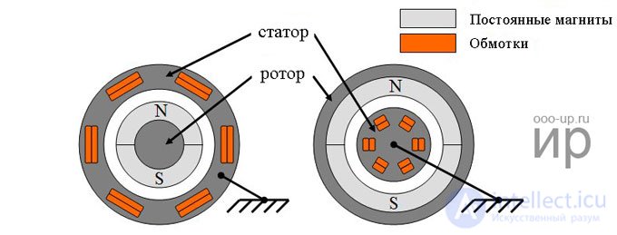
A permanent-magnet synchronous electric motor, like any rotating electric motor, consists of a rotor and a stator. The stator is the stationary part, the rotor is the rotating part.
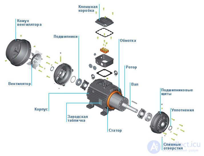
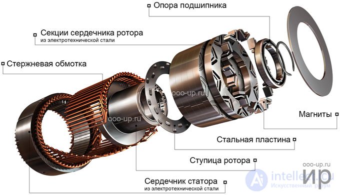
Usually the rotor is located inside the motor's stator; designs with an external rotor also exist — inside-out (inverted) type electric motors.
Like any electrical machine, a synchronous machine can operate in motor and generator modes.
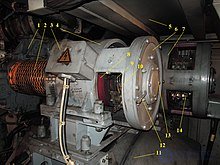
Synchronous generators are usually built with the armature located on the stator, for convenience in drawing off the electrical energy. Since the excitation power is small compared with the power taken from the armature (0.3...2%), supplying direct current to the field winding via two slip rings does not present any particular difficulties. The operating principle of a synchronous generator is based on the phenomenon of electromagnetic induction; as the rotor rotates, the magnetic flux produced by the field winding links successively with each of the phases of the stator winding, inducing an EMF in them. In the most common case of using a three-phase distributed armature winding, a sinusoidal EMF is induced in each of the phases, which are offset from one another by 120 degrees. By connecting the phases in the standard «delta» or «wye» configurations, a three-phase voltage is obtained at the generator output, which is the generally accepted standard for trunk power grids.
The frequency of the induced EMF  [Hz] is related to the rotor speed
  [rpm] by the relation:
 ,
,
where  — is the number of pole pairs.
Synchronous generators are often used instead of commutator machines to generate direct current, connecting their armature windings to three-phase rectifiers — on diesel locomotives (for example, TEP70, 2TE116), automobiles, aircraft. This is done because of the much higher reliability and overhaul interval of synchronous machines.
The operating principle of a synchronous motor is based on the interaction of the rotating magnetic field of the armature and the magnetic field of the inductor poles. Usually the armature is located on the stator, and the inductor — on the rotor. In high-power motors, electromagnets are used as poles (current is fed to the rotor through a brush-ring sliding contact), while in low-power motors, for example in hard-disk-drive motors — permanent magnets are used. There is an inverted motor design, in which the armature is located on the rotor, and the inductor — on the stator (in older motors, as well as in modern cryogenic synchronous machines, in which superconductors are used in the field windings).
Starting the motor. The motor needs to be accelerated to a frequency close to the rotation speed of the magnetic field in the air gap before it can operate in synchronous mode. At this speed, the rotating magnetic field of the armature locks in with the magnetic fields of the inductor poles: if the inductor is located on the stator, then the rotating magnetic field of the rotating armature (rotor) turns out to be stationary relative to the constant field of the inductor (stator); if the inductor is on the rotor, then the magnetic field of the rotating inductor poles (rotor) is stationary relative to the rotating magnetic field of the armature (stator) — this phenomenon is called «pulling into synchronism».
For acceleration, an asynchronous mode is usually used, in which the inductor windings are short-circuited through a rheostat or directly, as in an asynchronous machine; for this starting mode, a short-circuited winding is made on the rotor in such machines, which also acts as a damper winding that eliminates rotor "hunting" during synchronization. After reaching a speed close to the rated one (> 95% — the so-called subsynchronous speed), the inductor is fed with direct current.
In motors with permanent magnets, an external starting motor or variable-frequency starting is used; variable-frequency control is also applied to all types of synchronous motors in operating mode — for example, on the traction motors of the TGV high-speed train. Motors of old record players required manual starting — spinning the record by hand; later, asynchronous motors came to be used in record players.
Sometimes a small generator (DC or AC with rectification), the so-called exciter, is mounted on the shaft of large machines to supply the field winding. In some cases (for example, on diesel locomotives) the exciter is installed separately and is driven through a step-up gearbox.
The rotor speed [rpm] remains constant, rigidly linked to the mains frequency [Hz] by the relation:
 ,
,
where — is the number of stator pole pairs; depending on the load of the machine, only the load angle (theta angle) changes — the electrical angle by which the excitation field lags or leads the armature field. At a load angle greater than 90 electrical degrees, the machine falls out of synchronism — it stops if the shaft is overloaded by a braking torque, or it runs away to higher speed if the machine is operating as a generator and is underloaded electrically.
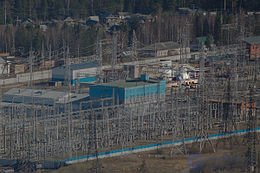
When the excitation is changed, synchronous motors change their power factor (cosine phi) from capacitive to inductive. Overexcited synchronous motors running at no load are used as reactive power compensators. In industry, synchronous motors are usually used at unit power ratings above 300 kW (blowers, water-pumping and oil-pumping stations), for example of the STD type; at lower power ratings, a simpler (and more reliable, including at start-up) squirrel-cage induction motor is usually used.
A hydrogenerator is a salient-pole synchronous generator designed to generate electrical energy when driven by a hydraulic turbine (at low rotational speeds, 50 — 600 min–1).
A turbogenerator is a non-salient-pole (round-rotor) synchronous generator designed to generate electrical energy when driven by a steam or gas turbine at high rotor speeds — 6000 (rarely), 3000, 1500 rpm.
A synchronous condenser is a synchronous motor designed to generate reactive power, operating without a load on the shaft (in no-load mode); in this case, practically only reactive current flows through the armature winding. A synchronous condenser can operate in power-factor-improvement mode or in voltage-stabilization mode. It provides an inductive load.
A doubly-fed machine (in particular, an ASM) is a synchronous machine in which the rotor and stator windings are supplied with currents of different frequencies, which creates asynchronous operating modes.
An impulse (short-circuit) generator is a synchronous generator (usually three-phase) designed for brief operation under short-circuit conditions (SC).
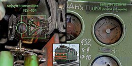
A synchro (selsyn) is a low-power synchronous machine used as a rotation-angle sensor, or in a pair with another synchro to transmit a rotation angle without a direct mechanical connection.
Gearless, stepper, inductor, hysteresis, and brushless synchronous motors also exist.
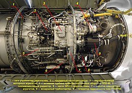
The classic synchronous machine has a weak point — slip rings with brushes, which wear out faster than the other parts of the machine due to electrical erosion and simple mechanical wear. In addition, brush sparking can become a cause of explosion. For this reason, brushless three-machine synchronous generators first became widespread in aviation, and later in other fields as well (in particular, on autonomous diesel generator sets). Such a unit houses three machines — a pilot exciter, a main exciter, and a generator, whose rotors turn on a common shaft. The pilot exciter is a synchronous generator excited by permanent magnets rotating on its rotor; its voltage is fed to the generator control unit, where it is rectified, regulated, and supplied to the stator winding of the exciter. The stator field induces a current in the exciter winding, which is rectified by a rotating rectifier assembly (RRA) mounted on the shaft and fed into the generator's field winding. The generator itself then produces the current that goes to the consumers.
This arrangement ensures both the absence of any moving mechanical parts in the machine other than the bearings, and the autonomous operation of the generator — as long as the generator is rotating, the pilot exciter supplies a voltage that can be used to power the generator's control circuits.
The choice of a simple and reliable starting circuit is of great importance for the operation of motors and synchronous compensators. At present, the simplest and at the same time most reliable circuit is direct-on-line starting at full mains voltage; the exceptions are motors with very severe starting conditions, or very high-power motors and compensators that cause unacceptable voltage dips in the mains during starting.
In cases where direct starting is unacceptable, the voltage applied to the motor at starting is reduced by inserting a reactor, or in rare cases an autotransformer, into the stator circuit. The design of all induction and synchronous motors provides for the possibility of asynchronous (induction) starting. To this end, synchronous motors with a rotational speed of up to 1500 rpm have a starting winding in the form of short-circuited bars located on the salient poles of the rotor. The possibility of asynchronous starting of turbo-motors with a rotational speed of 3000 rpm is provided primarily by currents in the body of the non-salient-pole rotor, as well as by copper wedges embedded in the slots.
The choice of a starting reactor for a synchronous motor and compensator is not fundamentally different from choosing a reactor for an induction motor. For high-power synchronous motors, it is in some cases advisable to supply power from separate transformers (unit transformers), the rating of the unit transformer in most cases corresponding to the rating of the installed motor. In this case, by dispensing with a circuit breaker on the motor side, the installation turns out to be quite simple. Only with frequent heavy starts may an increase in transformer rating be required, due to heating considerations.
Reactor starting and starting under the motor-transformer unit scheme have undeniable advantages over starting through an autotransformer. For example, when starting through a permanently connected reactor and transformer, the voltage at the motor or compensator rises smoothly as the starting current decreases, and by the end of starting this voltage differs only slightly from the rated value.
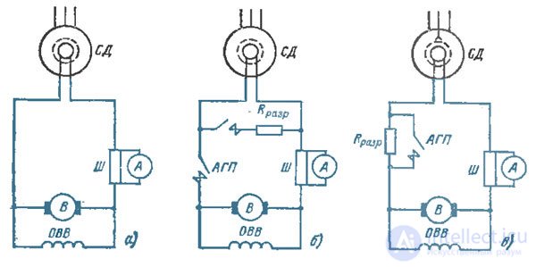
Fig. Direct-on-line starting circuits for synchronous motors with DC rotating exciters:
a - rotor winding is solidly connected to the exciter armature;
b - connected to a discharge resistor:
c - connected to the exciter armature through a discharge resistor.
Therefore, during reactor starting, the reactor is short-circuited (bypassed) practically without a shock (see, for example, Fig., b), unlike autotransformer starting, where special measures must be taken, complicating the starting circuit, to limit the current surge when switching from the starting voltage to the full network voltage.
The requirements of some transformer manufacturers to limit the starting current, which lead to oversizing the unit transformer's rating on the grounds of limiting dynamic forces on the winding, should be considered unjustified. According to GOST, a transformer winding must withstand, without damage, the short-circuit currents at the terminals of any of its windings when rated voltage is applied to the other. These currents are known to be substantially greater than the currents during starting of a motor comparable in power to the transformer. The dynamic forces in the transformer, being proportional to the square of the current, therefore turn out to be considerably lower than the guaranteed values.
The practice of using transformer-motor unit schemes has fully justified itself. When an electric-machine excitation system is used, as can be concluded from the processes discussed above in these systems during starting of the motor (condenser), preference should be given to schemes with the exciter permanently (solidly) connected to the rotor of the motor (condenser), provided this is permissible under the starting conditions. In this case, the resistance in the exciter's field circuit must be selected so that, at rated angular speed, the voltage on the motor (condenser) when disconnected from the network is equal to the network voltage or somewhat higher.
The motor (condenser) is started as follows: the main circuit breaker is closed, the motor (condenser) accelerates, is excited, and is pulled into synchronism smoothly, without shocks and without any intervention by personnel or any automatic elements issuing a command to excite the machine. This scheme is applicable to motors and condensers that have the exciter on the same shaft, as well as to those fed from a separately mounted motor-generator set. In the latter case, starting of the excitation unit must be carried out simultaneously with the starting of the motor or condenser by closing the auxiliary (interlock) contacts of the main motor's circuit breaker.
With the stator winding connected directly to the network and a permanently connected exciter, the starting scheme of a synchronous machine (Fig. a) is just as simple as the starting scheme of an induction motor with a squirrel-cage rotor. However, the tests carried out and the accumulated operating experience show that the field of application of starting schemes for synchronous motors with a permanently connected exciter is practically limited to motors of relatively low power – as a rule, not exceeding 2000 kW. The scheme is unsuitable for motors starting under a load above 0,4-0,6 of rated power, owing to the dip in the asynchronous torque curve in the region of low slip, and is of little effectiveness for motors in which a field (excitation) contactor turns out to be necessary for field suppression or for implementing a resynchronization scheme. For example, tests conducted have shown this scheme to be unsuitable for synchronous motors SDM-20-49-60, 2000 kW, used to drive ball coal-pulverizing mills Sh-50 and Sh-50A on the 300 MW power units of large thermal power plants. The torque curve during starting of these mills has a sharply pronounced pulsating character, as a result of which the shaft is subjected to an alternating-sign load.
When starting a motor with an exciter permanently connected to the rotor, the torque curve has a particularly unfavorable character, so successful starting of such units has proven possible only using a circuit in which the rotor winding is connected to the exciter armature through a discharge resistor (Fig. c). During direct starting, the mechanical stresses in the end windings of the stator windings of induction and synchronous motors and compensators increase, but, as a rule, owing to the voltage drop in the network, they turn out to be lower than the stresses that occur during nearby short circuits.
Most electric motors may be switched to direct starting without additional reinforcement of the end-winding fastenings. However, in certain cases (large starting current ratios combined with small drops in mains voltage, weak fastening of the stator end windings), such reinforcement may be required. For this purpose, it can be recommended to install additional spacer braces and to cross-lash adjacent end windings at the locations of previously installed and additional braces.
Operating experience shows numerous cases of the use of direct starting for wound-rotor induction motors converted to squirrel-cage operation or started without a rheostat in the rotor circuit, as well as for motors previously started from an autotransformer or through a reactor. Experience has confirmed the feasibility of converting these motors to direct starting. Unloaded starting of two-speed motors should always be performed at the lower angular speed. If operation at the higher angular speed is required, then after starting the motor at the lower angular speed, the running motor should be switched to the higher angular speed. With such starting, the total losses during starting will be minimal.
For production machinery to operate with maximum efficiency, the electric motor used as the drive must be correctly selected. In this article we will look at how induction and synchronous motors differ in terms of design features, functionality, and cost-effectiveness.
Electric motors are devices for converting electrical energy into mechanical energy. The basic design of a motor (whether synchronous or induction type) consists of the following elements:
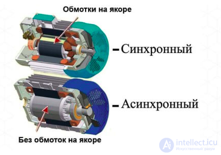
The stators of motors of both categories have a similar design principle. Current-carrying conductors made of copper or aluminum are laid in special slots (axial grooves). The function of the stator is to create a rotating magnetic field. The rotor (with the field winding) is mounted on the motor shaft and rotates under the action of the electromotive force that arises.
The main difference between a synchronous and an induction motor lies in the design of the rotor.
The rotors of synchronous motors are permanent or electric magnets. The constant magnetic field they create interacts with the rotating magnetic field of the stator.
In the case of an induction motor (also called an asynchronous motor), short-circuited metal bars are inserted into the rotor slots. In addition to the squirrel-cage type, wound rotors are also used, fitted with slip rings that are short-circuited after the motor has run up to speed.
As a result, the ratio between the rotational frequency of the loaded motor and the rotational frequency inherent to the stator's magnetic field is, for different motor types, as follows:
Based on an understanding of how an induction motor differs from a synchronous motor, the main advantages and disadvantages of these motors can be formulated.
Synchronous-type motors are more complex to use, since they:
Induction models are characterized by:
At the same time, synchronous motors offer greater capabilities in terms of power factor and are also less sensitive to voltage fluctuations, but the cost of such units is higher, which makes their use less advantageous.

Comments