
Lecture
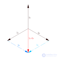
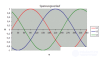
A three-phase power supply system is a special case of multiphase AC electrical circuit systems, in which sinusoidal EMFs of the same frequency, generated by a common source, act while being shifted relative to one another in time by a certain phase angle. In a three-phase system, this angle equals 2π/3 (120°).
Each of the acting EMFs is at its own phase of the periodic process, and is therefore often simply called a "phase." The conductors that carry these EMFs are also called "phases." In three-phase systems, the shift angle equals 120 degrees. In the Russian Federation, phase conductors are denoted by the Latin letter L with a numerical index 1…3, or by A, B and C .
Common designations for phase conductors:
| Russia, EU (above 1000 V) | Russia, EU (below 1000 V) | Germany | Denmark |
|---|---|---|---|
| A | L1 | L1 | R |
| B | L2 | L2 | S |
| C | L3 | L3 | T |
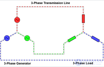
In addition to phase conductors, a neutral conductor (N - "neutral" or "zero") is used in networks up to 1000 volts. It allows a three-phase network to be used to supply single-phase loads at phase voltage.
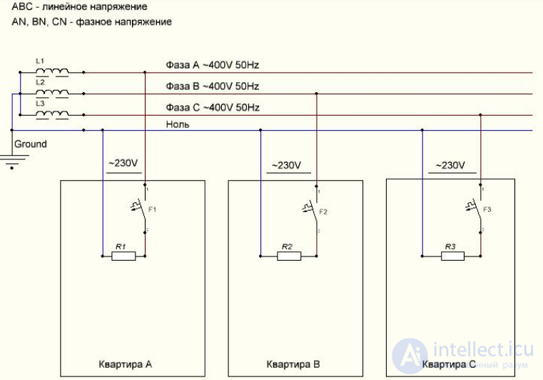
A possible wiring diagram of a three-phase network in multi-apartment residential buildings
Thanks to these advantages, three-phase systems are the most widespread in modern electric power engineering.
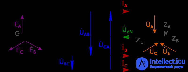
A wye (star) connection is one in which the ends of the phase windings of the generator (G) are joined at a single common point, called the neutral point or neutral. The ends of the phase windings of the consumer (M) are also joined at a common point.
The conductors connecting the beginnings of the phases of the generator and the consumer are called line conductors. The conductor connecting the two neutrals is called the neutral conductor.
That is, a line conductor is a phase conductor in three-phase circuits
A three-phase circuit that has a neutral conductor is called a four-wire circuit. If there is no neutral conductor, it is called a three-wire circuit.
If the resistances Za, Zb, Zc consumer are equal to one another, such a load is called balanced.
The voltage between a phase conductor and the neutral (Ua, Ub, Uc) is called the phase voltage. The voltage between two phase conductors (UAB, UBC, UCA) is called the line voltage. For a wye (star) winding connection, under a balanced load, the following relationship between line and phase currents and voltages holds:

It is easy to show that the line voltage is shifted in phase by  relative to the phase voltages:


For a wye (star) winding connection, under a balanced load, the power of the three-phase network is equal to 
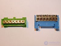
Under a balanced load in a three-phase system, supplying the consumer with line voltage is possible even in the absence of a neutral conductor. Despite this, when the load is supplied with phase voltage and the load on the phases is not strictly balanced, the presence of a neutral conductor is mandatory. If it breaks, or if its resistance increases significantly (poor contact), a so-called phase imbalance occurs, as a result of which the connected load, rated for phase voltage, may end up under an arbitrary voltage ranging from zero to the line voltage (the specific value depends on the distribution of the load across the phases at the moment the neutral conductor breaks). This is often the cause of failure of household electronics in apartment buildings, which can lead to fires. A reduced voltage can also cause equipment to fail.
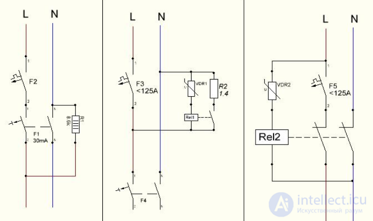
Existing types of protection against line overvoltage available for purchase in electrical equipment stores
Modern equipment is increasingly fitted with switch-mode power supplies. A switch-mode power supply without a power-factor corrector draws current in narrow pulses near the peaks of the supply voltage sine wave, during the charging intervals of the input rectifier's capacitor. A large number of such power supplies on the network creates an elevated third-harmonic current in the supply voltage. Currents of harmonics that are multiples of the third, instead of cancelling each other out, add up arithmetically in the neutral conductor (even with a symmetrical load distribution) and can lead to its overload even without exceeding the allowable power consumption per phase. This problem exists, in particular, in office buildings with a large amount of office equipment operating simultaneously. The solution to the third-harmonic problem is the use of a power-factor corrector (passive or active) as part of the circuitry of the switch-mode power supplies being produced. The requirements of the IEC 1000-3-2 standard impose limits on the harmonic components of the load current of devices with a power rating of 50 W and above. In Russia, the number of harmonic components of the load current is regulated by the standards GOST R 54149-2010, GOST 32144-2013 (from 1.07.2014), and OST 45.188-2001.
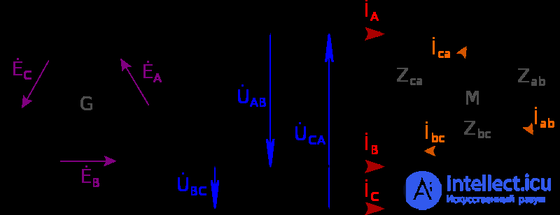
Delta — a connection in which the end of the first phase is connected to the start of the second phase, the end of the second phase to the start of the third, and the end of the third phase is connected to the start of the first.
For a delta winding connection, under a balanced load, the following relationship between line and phase currents and voltages holds:

For windings connected in delta, under symmetrical load, the power of the three-phase current is equal to:

| Country | Frequency, Hz | Voltage (phase/line), Volts |
|---|---|---|
| Russia | 50 | 230/400 (household networks) 230/400, 380/660, 400/690, 3000, 6000, 10000 (industrial networks) |
| EU countries | 50 | 230/400, 400/690 (industrial networks) 660 450 |
| Japan | 50 (60) | 100/208 |
| USA | 60 | 120/208, 277/480 240 (delta only) |
A four-wire three-phase circuit is widely used for supplying power to industrial enterprises, factories, and residential buildings.
The wires connecting the phases of the generator and the receiver are called line wires (wires A-A, B-B, C-C). Point O is the zero (neutral) point of the generator, and correspondingly point O' is the zero (neutral) point of the receiver, the load. The wire connecting points O – O' is called the zero, or neutral, wire.
The voltage between the beginning and the end of a phase is called the phase voltage (UA, UB, UC). The current flowing through a phase is called the phase current (IA, IB, IC). The voltage between any two line wires is called the line voltage (UAB, UBC, UCA).
The current flowing through a line wire is called the line current (IA, IB, IC). As can be seen from the diagram in Fig. 3.4, if the loads are connected in a wye (star) with a neutral wire, the phase current equals the line current (Iph = Il), and the voltages differ by a factor of  (
(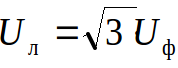 ). In this scheme there can be two voltages differing by a factor of
  , which is why GOST has established the following rated voltages for AC loads — 127, 220, 380, 660 V, and accordingly three systems are used: 220/127; 380/220 and 660/380.
The line voltages are equal to the differences of the phase voltages:
 .
.
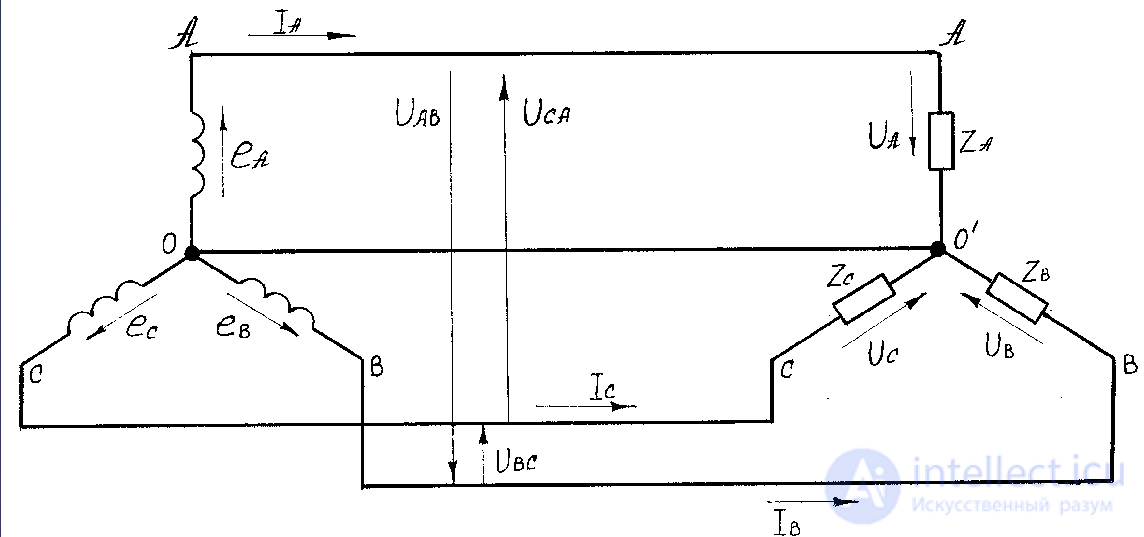
Fig. 3.4. Diagram of a four-wire three-phase circuit
If the three phases of the load have identical impedances zA = zB = zC, the circuit then operates in a symmetrical mode, which is the main operating mode. Examples of symmetrical loads include three-phase transformers and three-phase induction motors.
The currents in the phases are equal and are determined by Ohm's law:
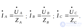 .
.
The phase shift angles are determined separately for each phase:
 .
.
The current in the neutral wire in this case will be equal to zero:
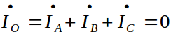 .
.
The voltage between the neutrals of the generator and the load is also equal to zero:
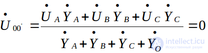 ,
,
where 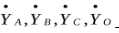 – is the conductance of the three-phase wires and one neutral wire.
The phasor diagram for the case of a symmetrical load is constructed as follows (Fig. 3.5).
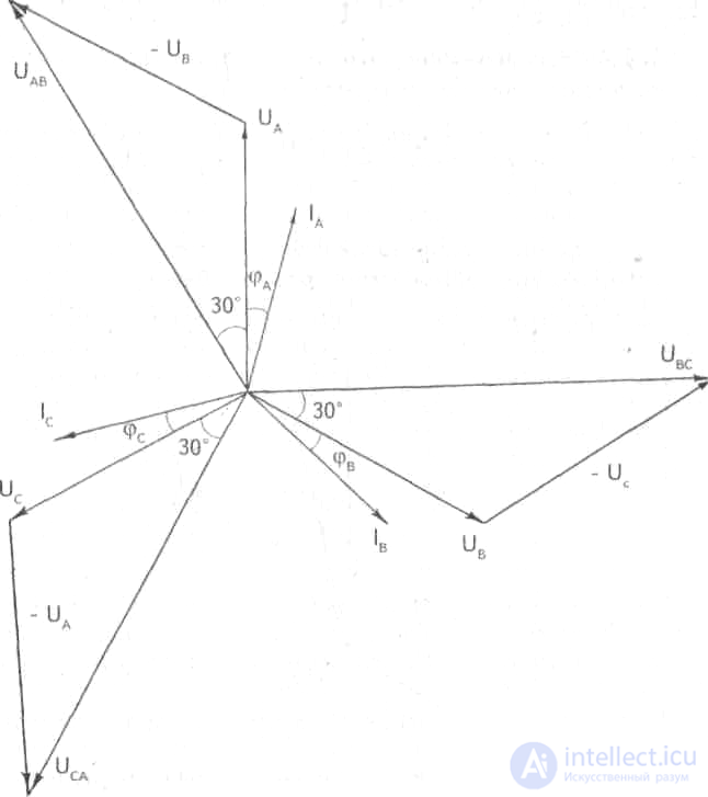
Fig. 3.5. Phasor diagram for the symmetrical-load mode with loads connected in a wye (star)
We lay off three phase-voltage phasors  at an angle of 120° to one another. The phase-current phasors
  lag behind the phasors of the corresponding voltages
  by angles φA,φB,φC (resistive-inductive load). The star of line voltages leads the star of phase voltages by an angle of 30°.
If the three phases of the load have different impedances zA ≠ zB ≠ zC , then the currents will also be unequal IA ≠ IB ≠ IC . The current in the neutral wire is determined from the phasor diagram (Fig. 3.6) or analytically. The voltage between the neutrals of the generator and the load U00 ≠ 0. The neutral wire serves to maintain a constant voltage on the phases of the load, therefore the installation of fuses and switches in the neutral wire is prohibited.
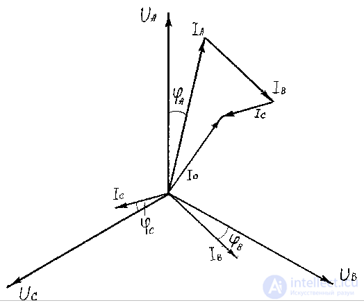
Fig. 3.6. Phasor diagram for the unbalanced load mode with consumers connected in wye (star)
If one of the line conductors breaks (due to a blown fuse, a phase being disconnected from the network, etc.) — for example, conductor A — the two other phases continue to operate in the same mode in which they were operating, UB = UC = Uph. Since IA = 0, the current in the neutral wire is
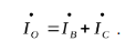 .
.
Conductors belonging to different phases are marked with different colors. The neutral and protective conductors are also marked with different colors. This is done to ensure proper protection against electric shock, as well as for the convenience of servicing, installing, and repairing electrical installations and electrical equipment — phasing (the phase sequence, i.e., the order in which currents flow through the phases) is essential, since the direction of rotation of three-phase motors, the correct operation of controlled three-phase rectifiers, and certain other devices depend on it. Conductor marking has its own differences from country to country, but many countries adhere to the general principles of color marking of conductors set out in the International Electrotechnical Commission standard IEC 60445:2010.
The conductors of a three-phase system are usually identified by a color code to ensure a balanced load and to ensure correct phase rotation for motors. The colors used may conform to the international standard IEC 60446 (later IEC 60445), to older standards, or may not conform to any standard at all, and may even differ within the same installation. For example, in the United States and Canada, different color codes are used for grounded and ungrounded systems.
| Country | Phases | Neutral, N |
Protective earth, PE |
||||||||
|---|---|---|---|---|---|---|---|---|---|---|---|
| L1 | L2 | L3 | |||||||||
|
Australia and New Zealand (AS/NZS 3000:2007, Fig. 3.2, or IEC 60446, as adopted by AS 3000) |
 |
Red or brown |  |
White; formerly yellow |  |
Dark blue or grey |  |
Black or blue |  |
Green / yellow-striped; very old installations, green |
|
| Canada | Mandatory | |
Red |  |
Black |  |
Blue |   |
White or grey |  |
Green, possibly, with yellow stripes, or bare (without insulation) |
| Isolated systems |  |
orange |  |
Brown |  |
Yellow |  |
White or grey |  |
Green, possibly yellow-striped |
|
|
European CENELEC (European Union and others; from April 2004, IEC 60446, later IEC 60445-2017), United Kingdom (from 31 March 2004), Hong Kong (from July 2007), Singapore (from March 2009), Russia (from 2009; GOST R 50462), Argentina, Ukraine, Belarus, Kazakhstan |
 |
Brown | |
Black |  |
Grey |  |
Blue |  |
Green / yellow stripes | |
| Old European (pre-IEC 60446, depending on the country) [note 7] | |||||||||||
|
United Kingdom (before April 2006), Hong Kong (before April 2009), South Africa, Malaysia, Singapore (before February 2011) |
|
Red |  |
Yellow |  |
Blue |  |
Black |  |
Green / yellow-striped; before c. 1970, green |
|
| India | |
Red |  |
Yellow |  |
Blue |  |
Black |  |
Green possibly yellow-striped |
|
| Chile - NCH 4/2003 |  |
Blue | |
Black | |
Red |  |
White |  |
Green possibly yellow-striped |
|
|
Former USSR (Russia, Ukraine, Kazakhstan; before 2009), People's Republic of China (GB 50303-2002, Section 15.2.2) |
|
Yellow |  |
Green | |
Red |  |
Light blue |  |
Green / yellow-striped | |
| Norway (before adopting CENELEC) | |
Black | |
White / gray |  |
Brown |  |
Blue |  |
Yellow-green stripe; previously yellow or uninsulated |
|
| United States |
Common practice |
 |
Black | |
Red |  |
Blue |  |
White or gray |  |
Green, possibly, with yellow stripes, or uninsulated |
|
Alternative practice |
 |
Brown |  |
Orange (delta) |  |
Yellow |   |
Gray or white |  |
Green | |
 |
Violet (wye) |
In low-voltage, high-frequency electronic speed controllers used in vehicle modeling, different marking systems are used:
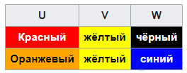
Neutral and ground conductors are generally absent due to the balanced nature of the load and the safety of the voltage.

Comments