
Lecture
In the field of electrical engineering, electrical admittance is a measure of how easily a circuit or device will allow current to flow. It is defined as the reciprocal of impedance, in the same way that conductance and resistance are related. The SI unit of admittance is the siemens (symbol S); an older, synonymous unit is the mho, whose symbol is ℧ (an upside-down capital omega, Ω). Oliver Heaviside coined the term «admittance» in December 1887.
Electrical admittance (Fr. admittance from Lat. admittere, to let through, to admit) — the complex conductance of a two-terminal network for a harmonic signal. In Russian-language literature this term is usually not used — instead, the term «complex conductance» is used (see, for example, (Bessonov 1978)).
The standard notation for admittance in formulas is Y or y, with dimension dim Y = L−2M−1T3I2, the SI unit of measurement is the siemens. Abbreviated designations — Cm, internationally — S.
Electrical admittance is defined as

where
Y - electrical admittance, measured in siemens.
Z - impedance, measured in ohms.
Resistance is a measure of the opposition a circuit presents to the flow of steady current, whereas impedance takes into account not only resistance but also dynamic effects (known as reactance). Similarly, conductance is not only a measure of the ease with which direct current can flow, but also the dynamic effects of a material's susceptibility to polarization:

where
 - electrical admittance, measured in siemens.
 - conductance, measured in siemens.
 is the susceptance, measured in siemens.
The dynamic effects of a material's susceptibility relate to the universal dielectric response, a power-law scaling of the system's conductivity with frequency under AC conditions.
Parts of this article or section rely on the reader's knowledge of the complex-impedance representation of capacitors and inductors, and of the frequency-domain representation of signals .
Impedance Z consists of a real part and an imaginary part,

where

Admittance, like impedance, is a complex number consisting of a real part (conductance, G ) and an imaginary part (susceptance, B ), thus:

where G (conductance) and B (susceptance) are defined as:
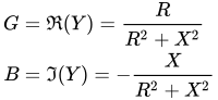
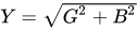
The magnitude and phase of admittance are defined as:
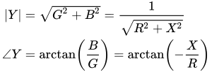
where
Note that (as shown above) the signs of the reactances are reversed in the admittance domain; that is, capacitive susceptance is positive, while inductive susceptance is negative.
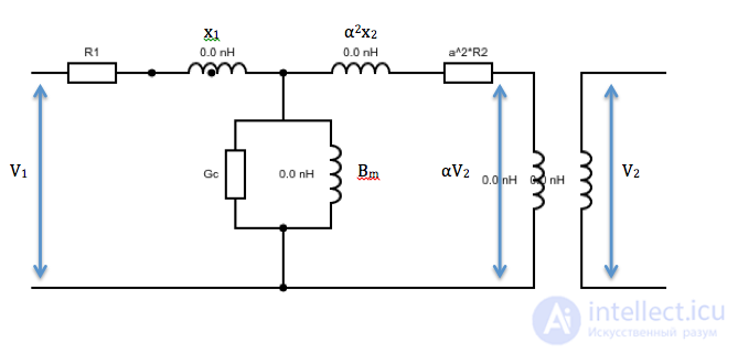
In the context of electrical modeling of transformers and transmission lines, shunt components, which provide paths of least resistance in certain models, are usually specified in terms of their admittance. Each side of most transformer models contains shunt components that model the magnetizing current and core losses. These shunt components may belong to the primary or secondary side. To simplify transformer analysis, the admittance of the shunt elements can be neglected. If the shunt components have a significant effect on system operation, the full shunt admittance must be taken into account. In the diagram below, all shunt conductances are referred to the primary side. The real and imaginary components of the full admittance and the shunt admittance are represented as Gc and B, respectively.
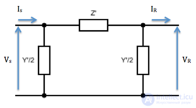
Transmission lines can extend for hundreds of kilometers, and the line's capacitance can affect voltage levels. For the analysis of short transmission lines, which applies to lines shorter than 80 kilometers, this capacitance can be neglected, and the model does not need shunt components. Lines from 80 to about 250 kilometers, usually classified as medium lines, have a shunt admittance given by

where
Admittance is understood as the quantity that is the reciprocal of impedance (total resistance):

where Z — impedance; G — the real component of the admittance (English conductance); B — the imaginary component of the admittance (English susceptance).
The real and imaginary components of admittance are related to the components of impedance as follows:
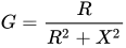 ;
; 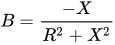
where R and X — are, respectively, the active and reactive components of the impedance
The magnitude of the admittance is:
The equivalent circuit of a passive linear two-terminal element in an AC circuit can be represented as two elements connected in parallel — an ideal resistor with purely active resistance and an ideal (linear, lossless) reactive element (a capacitor or an inductor). In such an equivalent representation, the active conductance of the resistor corresponds to the real component of the complex admittance, while the reactive conductance of the inductor or capacitor corresponds to the imaginary component.
Ohm's law, when using complex admittance, is written as:
 or
or 
where I — is the current; IA and IR — are the active and reactive components of the current; U — is the voltage across the section of the circuit
To measure admittance, immittance meters, impedance analyzers, and Q meters are used, with the measurement performed by an indirect method; in the microwave range, measurement lines and impedance meters are also used, likewise by an indirect method.

Comments