
Lecture
Electricity is not a storable resource. At present there are no efficient technologies that allow the energy generated by generators to be accumulated, so the transmission of electric power to consumers is an urgent task. The cost of the resource includes the costs of its production, losses during transportation, and the costs of installing and maintaining power lines. At the same time, the efficiency of the power supply system depends directly on the transmission scheme.
[[s|longdist]]
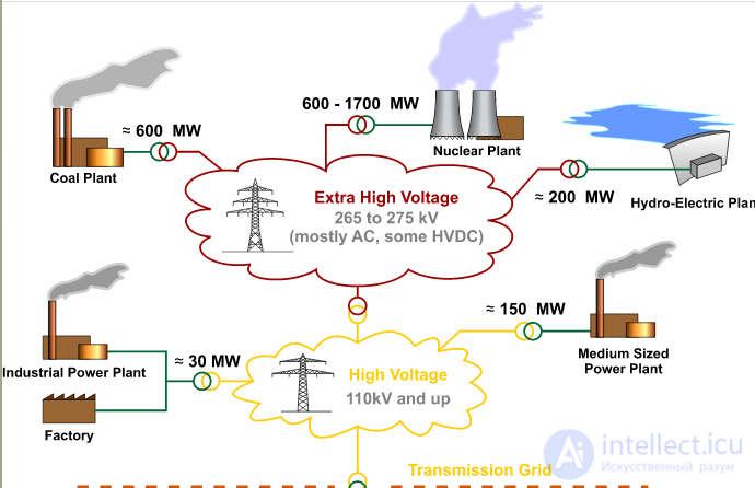

Despite the fact that in the internal networks of most consumers the voltage is typically 220/380 V, electric power is transmitted to them over high-voltage trunk lines and stepped down at transformer substations. There are compelling reasons for such an operating scheme: the fact is that the largest share of losses is due to heating of the conductors.
The power loss is described by the following formula: Q = I2 * RL ,
where I – is the current flowing through the line, RL – is its resistance.
Based on the formula given, it can be concluded that costs can be reduced either by decreasing the resistance of the power line or by lowering the current. In the first case it would be necessary to increase the cross section of the conductor, which is unacceptable, since it would lead to a significant increase in the cost of power transmission lines. Choosing the second option requires increasing the voltage, that is, the introduction of high-voltage power lines leads to a reduction in power losses.
In the power industry it is customary to divide power lines into types depending on the following characteristics:
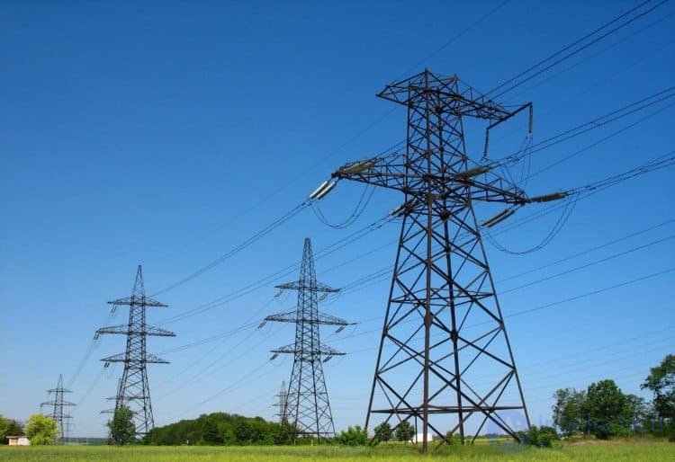
Overhead power transmission lines
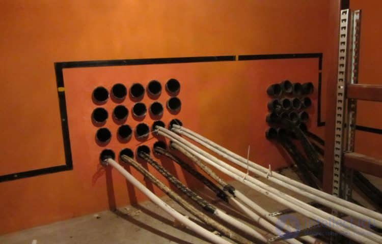
Construction of a block cable duct
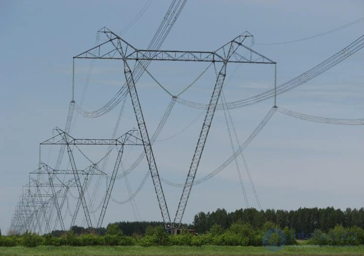
Ultra-high-voltage power line Ekibastuz–Kokshetau 1150 kV
Electric power can be transmitted in two ways:
In the first case, electric power is transmitted through conductors, which take the form of a wire or a conductive medium. This is precisely the method used in overhead and cable power lines. Converting electricity into another form of energy opens up prospects for wirelessly supplying consumers. This would make it possible to do away with power transmission lines and, accordingly, with the costs associated with their installation and maintenance. Below are promising wireless technologies that are currently being improved.
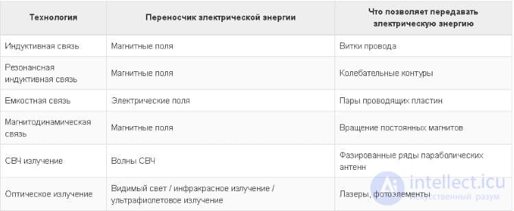
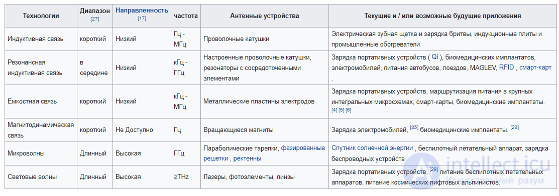
Wireless electricity transmission technologies
Unfortunately, at present the possibilities of transporting electricity wirelessly are severely limited, so it is still too early to speak of an effective alternative to the direct transmission method. Research work in this direction gives hope that a solution will be found in the near future.
The ultrasonic method of energy transmission was invented by students at the University of Pennsylvania and first presented to the general public at the «The All Things Digital» (D9) exhibition in 2011. As with other methods of wirelessly transmitting something, a receiver and a transmitter were used. The transmitter emitted ultrasound; the receiver, in turn, converted the audible signal into electricity. At the time of the presentation, the transmission distance reached 7-10 meters, and a direct line of sight between the receiver and transmitter was required. The transmitted voltage reached 8 volts; the resulting current is not reported. The ultrasonic frequencies used have no effect on humans. There is also no information on any negative effect of ultrasonic frequencies on animals.
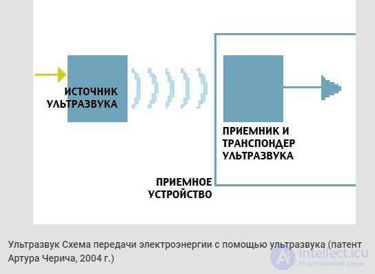
Practical application of ultrasound for energy transmission is impossible due to its very low efficiency, restrictions in many countries on the maximum sound pressure level that prevent an acceptable amount of power from being transmitted, and other limitations[35].
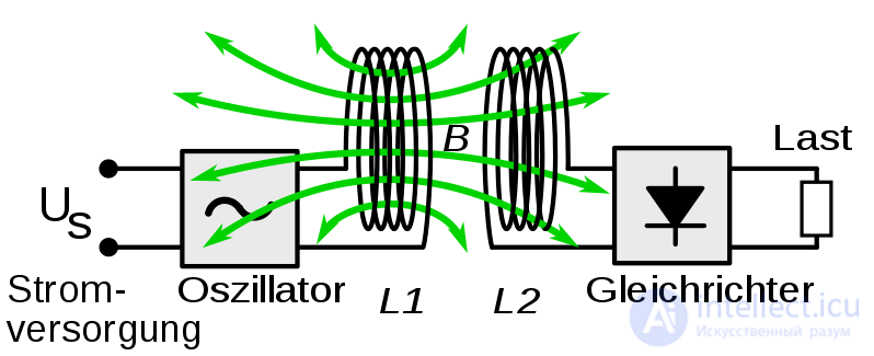
In wireless energy transmission by the electromagnetic induction method, the near electromagnetic field is used at distances of about one-sixth of a wavelength. The near-field energy is not itself radiative, although some radiative losses do still occur. In addition, resistive losses are typically present as well. Owing to electrodynamic induction, the alternating electric current flowing through the primary winding creates an alternating magnetic field that acts on the secondary winding, inducing an electric current in it. To achieve high efficiency, the coupling must be sufficiently close. As the secondary winding moves further from the primary, an increasing portion of the magnetic field fails to reach the secondary winding. Even at relatively short distances, inductive coupling becomes extremely inefficient, wasting most of the transmitted energy.
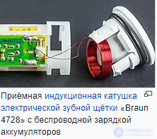
An electrical transformer is the simplest device for wireless energy transmission. The primary and secondary windings of a transformer are not directly connected. Energy transfer takes place through a process known as mutual induction. The main function of a transformer is to increase or decrease the primary voltage. Contactless chargers for mobile phones and electric toothbrushes are examples of the use of the electrodynamic induction principle. Induction cooktops also use this method. The main drawback of the wireless transmission method is its extremely short operating range. The receiver must be located in close proximity to the transmitter in order to interact with it effectively.
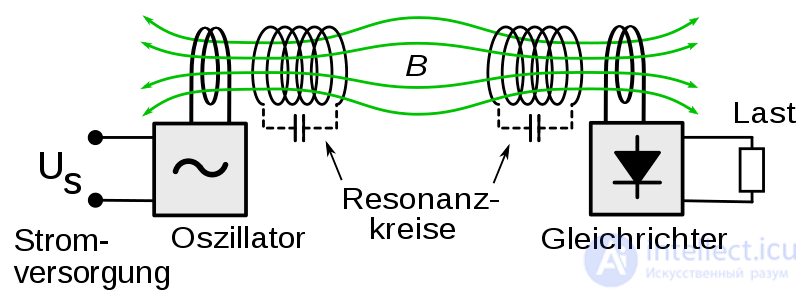
Using the resonance of an oscillating circuit somewhat increases the transmission range. In resonant induction, the transmitter and receiver are tuned to the same frequency. Performance can be improved further by changing the waveform of the drive current from sinusoidal to non-sinusoidal transient waveforms. Pulsed energy transmission occurs over several cycles. In this way, significant power can be transferred between two mutually tuned LC circuits with a relatively low coupling coefficient. The transmitting and receiving coils are typically single-layer solenoids or flat spirals with a set of capacitors that allow the receiving element to be tuned to the transmitter's frequency.
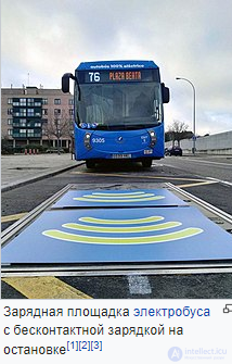
A common application of resonant electrodynamic induction is charging the batteries of portable devices such as laptops and cell phones, medical implants, and electric vehicles. The localized charging technique uses selection of the appropriate transmitting coil within an array of multilayer windings. Resonance is used both in the wireless charging pad (the transmitting circuit) and in the receiver module (built into the load) to ensure maximum energy transfer efficiency. This transmission technique is suitable for universal wireless charging pads for recharging portable electronics, such as mobile phones. The technique has been adopted as part of the Qi wireless charging standard.
Resonant electrodynamic induction is also used to power devices that have no batteries, such as RFID tags and contactless smart cards, as well as to transfer electrical energy from the primary inductor to the helical resonator of a Tesla transformer, which is likewise a wireless transmitter of electrical energy.
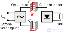
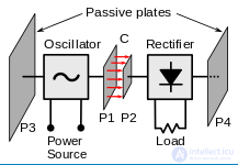
Electrostatic or capacitive coupling is the passage of electrical energy through a dielectric[clarify]. In practice, this is an electric field gradient or differential capacitance between two or more isolated terminals, plates, electrodes, or nodes raised above a conductive surface. The electric field is created by charging the plates with a high-frequency, high-potential alternating current. The capacitance between the two electrodes and the powered device forms a potential difference.
Electrical energy transmitted by means of electrostatic induction can be used in a receiving device, such as, for example, wireless lamps. Tesla demonstrated the wireless powering of lighting lamps with energy transmitted by an alternating electric field.
«Instead of relying on electrodynamic induction to power a lamp at a distance, the ideal way to illuminate a hall or room would be to create conditions in which a lighting fixture could be carried and placed anywhere, and it would work regardless of its location and without a wired connection. I was able to demonstrate this by creating a powerful high-frequency alternating electric field in a room. For this purpose, I attached an insulated metal plate to the ceiling and connected it to one terminal of an induction coil, the other terminal being grounded. In another case, I connected two plates, each to a different end of the induction coil, carefully selecting their dimensions. A gas-discharge lamp could be moved to any place in the room between the metal plates, or even some distance beyond them, while emitting light without interruption».
The principle of electrostatic induction is applicable to the method of wireless transmission. «In cases where only a small amount of energy needs to be transmitted, the need to place the electrodes at an elevation is reduced, especially in the case of high-frequency currents, when a sufficient amount of energy can be obtained by the terminal through electrostatic induction from the upper layers of air, created by the transmitting terminal».
Radio-wave energy transmission can be made more directional, significantly increasing the effective transmission range, by reducing the wavelength of the electromagnetic radiation, typically down to the microwave range. A rectenna, whose energy conversion efficiency exceeds 95%, can be used to convert microwave energy back into electricity. This method has been proposed for transmitting energy from orbital solar power stations to Earth and for powering spacecraft leaving Earth orbit.
A difficulty in creating a power microwave beam is that, because of diffraction limiting antenna directivity, a large-sized aperture is needed for use in space programs. For example, according to a 1978 NASA study, a microwave beam at a frequency of 2.45 GHz would require a transmitting antenna 1 km in diameter and a receiving rectenna 10 km in diameter. These sizes could be reduced by using shorter wavelengths, but short waves can be absorbed by the atmosphere and also blocked by rain or water droplets. Because of the "narrow-beam curse," it is impossible to narrow the beam by combining beams from several smaller satellites without a proportional loss of power. For terrestrial use, a 10 km diameter antenna would allow a significant power level to be achieved while keeping the beam density low, which is important for reasons of human and environmental safety. The power density level that is safe for humans is 1 mW/cm2, which over the area of a 10 km diameter circle corresponds to a power of 750 MW. This level corresponds to the power of modern power plants.
The Japanese researcher Hidetsugu Yagi studied wireless power transmission [citation needed 1471 days] using a directional antenna array he had created. In February 1926, he published a paper on the device now known as the Yagi antenna. Although it proved ineffective for power transmission, today it is widely used in broadcasting and wireless telecommunications due to its excellent operating characteristics.
In 1945, the Soviet scientist Semyon Tetelbaum published an article in which he was the first to examine the efficiency of a microwave link for the wireless transmission of electrical energy[15][16]. After World War II, when the development of powerful UHF emitters known as magnetrons began, the idea of using microwaves for energy transmission was developed further.
In 1964, a miniature helicopter was demonstrated, to which energy was transmitted by means of microwave radiation.
Wireless transmission of high-power energy using microwaves has been confirmed experimentally. Experiments transmitting tens of kilowatts of electrical energy were conducted at the Goldstone Observatory (Goldstone, California) in 1975 and in 1997 at Grand Bassin on Reunion Island. During the experiments, energy transmission was achieved over a distance of about one kilometer.
Experiments on the wireless transmission of energy using microwave radiation were also conducted by academician Pyotr Kapitsa.
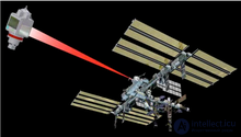
If the wavelength of the electromagnetic radiation approaches the visible region of the spectrum (from 10 µm to 10 nm), energy can be transmitted by converting it into a laser beam, which can then be directed onto the photocell of the receiver.
Compared with other wireless transmission methods, laser energy transmission has a number of advantages:
This method also has a number of drawbacks:
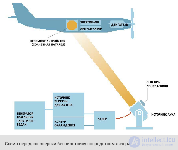
Laser power transmission technology was previously studied mainly in the development of new weapons systems and in the aerospace industry, and is now being developed for commercial and consumer electronics in low-power devices. Wireless energy transmission systems intended for consumer use must satisfy the laser safety requirements of the IEC 60825 standard. For a better understanding of laser systems, it should be taken into account that the propagation of a laser beam is far less dependent on diffraction limitations, how spatial and spectral matching of laser characteristics allows the operating power and distance to be increased, and how wavelength affects focusing.
NASA's Dryden Flight Research Center demonstrated the flight of a light unmanned model aircraft powered by a laser beam. This proved the possibility of periodic recharging via a laser system without the aircraft needing to land.
In addition, the NASA division called «Litehouse DEV», together with the University of Maryland, is developing an eye-safe laser power system for small UAVs.
Since 2006, PowerBeam, which invented the eye-safe laser technology, has also been developing commercially ready modules for various consumer and industrial electronic devices.
In 2009, in NASA's competition for laser power transmission in space, first place and a $900,000 prize were won by LaserMotive, which demonstrated its own development capable of operating at a distance of one kilometer. The winner's laser was able to transmit 500 W of power over a distance of 1 km with 10% efficiency.
The single-wire electrical system SWER (single wire with earth return) is based on earth current and a single insulated wire. In emergency cases, high-voltage DC lines can operate in SWER mode. Replacing the insulated wire with an atmospheric return path for transmitting high-power high-frequency alternating current became one of the methods of wireless power transmission. In addition, the possibility of wireless power transmission through the earth alone has been investigated.
Low-frequency alternating current can be transmitted with low losses through the earth, since the total resistance of the earth is significantly less than 1 Ω[36]. Electrical induction arises mainly due to the electrical conductivity of the oceans, metallic ore bodies and similar underground structures. Electrical induction is also caused by electrostatic induction of dielectric regions, such as deposits of quartz sand and other non-conductive minerals[37][38].
Alternating current can be transmitted through layers of the atmosphere having an atmospheric pressure of less than 135 mm Hg[39]. Current flows by means of electrostatic induction through the lower layers of the atmosphere at approximately 2-3 miles (3.2-4.8 kilometers) above sea level[40] and due to ion flow, that is, electrical conductivity through the ionized region located at an altitude above 5 km. Intense vertical beams of ultraviolet radiation can be used to ionize atmospheric gases directly above two elevated terminals, leading to the formation of plasma high-voltage transmission lines running directly to the conductive layers of the atmosphere. As a result, a flow of electric current forms between the two elevated terminals, passing up to the troposphere, through it, and back to the other terminal. Electrical conductivity through the layers of the atmosphere becomes possible due to capacitive plasma discharge in the ionized atmosphere[41][42][43][44].
Nikola Tesla discovered that electric power could be transmitted both through the earth and through the atmosphere. In the course of his research, he achieved the lighting of a lamp at moderate distances and recorded the transmission of electric power over great distances. The Wardenclyffe Tower was conceived as a commercial project for transatlantic wireless telephony and became a real demonstration of the possibility of wireless power transmission on a global scale. The installation was not completed due to insufficient funding[45].
The earth is a natural conductor and forms one conducting loop. The return loop is realized through the upper layers of the troposphere and the lower layers of the stratosphere at an altitude of about 4.5 miles (7.2 km)[46].
A global system of wireless power transmission, the so-called „World Wireless System“, based on the high electrical conductivity of plasma and the high electrical conductivity of the earth, was proposed by Nikola Tesla at the beginning of 1904 and, according to one hypothesis, could well have been the cause of the Tunguska meteorite, which resulted from a „short circuit“ between the charged atmosphere and the earth[47][48].
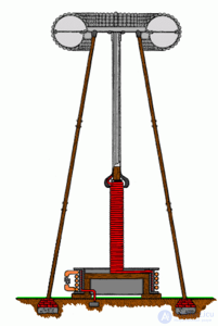
Design of Tesla's transmitting coil
U.S. Patent 1 119 732
Nikola Tesla's early experiments, the famous Serbian inventor, concerned the propagation of ordinary radio waves, i.e., Hertzian waves, electromagnetic waves propagating through space.
In 1919 Nikola Tesla wrote: «It is believed that I began work on wireless transmission in 1893, but in fact for the two preceding years I had been conducting research and building apparatus. It was clear to me from the very outset that success could be achieved only through a number of radical solutions. High-frequency generators and electrical oscillators had to be created first. Their energy had to be converted by efficient transmitters and received at a distance by suitable receivers. Such a system would be effective provided any outside interference were excluded and its complete exclusivity were ensured. In time, however, I realized that for devices of this kind to work effectively, they had to be designed with the physical properties of our planet in mind».
One of the conditions for creating a worldwide wireless system is the construction of resonant receivers. A grounded helical resonator of a Tesla coil and a terminal placed on an elevation can be used for this purpose. Tesla himself repeatedly demonstrated the wireless transmission of electrical energy from a transmitting to a receiving Tesla coil. This became part of his wireless transmission system (US patent No. 1,119,732 of January 18, 1902, «Apparatus for Transmitting Electrical Energy»). Tesla proposed installing more than thirty receiving-transmitting stations around the world. In this system the receiving coil acts as a step-down transformer with high output current. The parameters of the transmitting coil are identical to those of the receiving coil.
The goal of Tesla's worldwide wireless system was to combine energy transmission with broadcasting and directed wireless communication, which would make it possible to do away with numerous high-voltage transmission lines and would help unite electrical generators on a global scale.
Atmospheric connection of plasma channels
When an atmospheric plasma channel connection occurs, energy is transferred between two electrodes via electrical conductivity through ionized air. [106] When there is an electric field gradient between two electrodes exceeding 34 kilovolts per centimeter at sea-level atmospheric pressure, an electric arc occurs. [107] This atmospheric dielectric breakdown causes electric current to flow along a random path through the ionized plasma channel between the two electrodes. An example of this is natural lightning, where one electrode is a virtual point in a cloud and the other is a point on the Earth. Research is currently being conducted on the laser-induced plasma channel (LIPC), using ultrafast lasers to artificially stimulate the development of a plasma channel through air, to direct the electric arc, and to direct the current along a specific path in a controlled manner. [108] The laser energy reduces the dielectric breakdown voltage in the atmosphere, and the air becomes less insulating due to overheating, which reduces the density ({\ displaystyle p} ) of the air filament. [109]
This new process is being studied for use as a laser lightning rod and as a means of triggering lightning strikes from clouds for research into the natural lightning channel, [110] for research into artificial propagation in the atmosphere, as a replacement for conventional radio antennas, [111] for applications related to electric welding and machining, [112] [113] for diverting energy from high-voltage capacitor discharges, for use in directed-energy weapons that employ electrical conductivity through a grounded return path, [114] [115] [116] [117] and electronic jamming.
The figure below shows typical schemes, of which the first two belong to the open (radial) type, while the rest belong to the closed (loop) type. The difference between them is that open configurations are not redundant, i.e., they have no backup lines that can be brought into service in the event of a critical increase in electrical load.
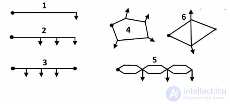
Example of the most common power line configurations
Legend:
Now let us examine in more detail the radial scheme for transmitting generated electricity over AC and DC power lines.
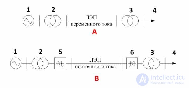
Fig. 6. Schemes for transmitting electricity to consumers using power lines with alternating (A) and direct (B) current
Legend:
As can be seen from scheme (A), electricity from the energy source is fed to a step-up transformer, then, using overhead power lines, the electricity is transported over considerable distances. At the end point, the line is connected to a step-down transformer, from which it goes to the distributor.
The method of transmitting electricity as direct current (B in Fig. 6) differs from the previous scheme in that it has two conversion units (5 and 6).
To conclude this section, for clarity let us present a simplified version of an urban network diagram.
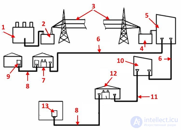
An illustrative example of a power supply block diagram
Legend:
The main problem associated with this task is the growth of losses as the length of the transmission line increases. As already mentioned above, to reduce the energy cost of transmitting electricity, the current is reduced by increasing the voltage. Unfortunately, this solution creates new problems, one of which is corona discharge.
From the standpoint of economic feasibility, losses in an overhead line (OHL) should not exceed 10%. Below is a table giving the maximum length of lines that meet the profitability conditions.
Table 1. Maximum length of transmission lines considering profitability (no more than 10% losses)
| OHL voltage (kV) | Length (km) |
| 0,40 | 1,0 |
| 10,0 | 25,0 |
| 35,0 | 100,0 |
| 110,0 | 300,0 |
| 220,0 | 700,0 |
| 500,0 | 2300,0 |
| 1150,0* | 4500,0* |
* — currently, the ultra-high-voltage overhead line has been switched to operate at half of its rated voltage (500,0 kV).
As an alternative to long-distance AC power transmission, DC overhead lines can be considered. Such transmission lines have the following advantages:
Despite the listed capabilities of DC transmission lines, such lines have not become widespread. This is primarily due to the high cost of the equipment needed to convert sinusoidal voltage into direct voltage. DC generators are practically never used, except at solar power plants.
Inversion (a process completely opposite to rectification) is also not straightforward; achieving high-quality sinusoidal characteristics is necessary, which significantly increases the cost of the equipment. In addition, one must take into account problems with organizing power tapping and the low profitability of lines shorter than 1000-1500 km.
The resistance of conductors can be significantly reduced by cooling them to ultra-low temperatures. This would raise the efficiency of electricity transmission to a qualitatively new level and increase the length of lines for using electricity far from its place of generation. Unfortunately, technologies currently available cannot allow the use of superconductivity for these purposes due to economic infeasibility.

Comments