
Lecture
Power factor — a dimensionless physical quantity that characterizes a consumer of alternating electric current in terms of the presence of a reactive component and distortion power in the load (the collective term for these being non-active power). In English-language (radio-)engineering literature it is referred to as "Power Factor". The concept of «power factor» should be distinguished from the concept of «cosine phi», which is equal to the cosine of the phase shift of the alternating current flowing through the load relative to the voltage applied to it. The second concept is used in the case of sinusoidal current and voltage, and only in that case are the two concepts equivalent. It is considered that the higher the power factor, the higher the quality of power consumption.
The power factor is equal to the ratio of the active power consumed by an electrical load to the apparent power. Active power is expended in doing work. In the case of sinusoidal current and voltage, the apparent power is the geometric sum of the active and reactive powers. In other words, it is equal to the square root of the sum of the squares of the active and reactive powers. In general, the apparent power can be defined as the product of the RMS (root-mean-square) values of the current and voltage in the circuit. Volt-amperes (V·A) are conventionally used as the unit of apparent power instead of watts (W).
In electric power engineering, the accepted notations for the power factor are  (where
  — the phase shift between the current and the voltage) or
  . When is used to denote the power factor, its value is usually expressed as a percentage.
According to the Cauchy—Bunyakovsky inequality, the active power, equal to the average value of the product of current and voltage, always does not exceed the product of the corresponding RMS values. Therefore, the power factor takes values from zero to one (or from 0 to 100 %).
The power factor can mathematically be interpreted as the cosine of the angle between the current and voltage vectors (in the general case, infinite-dimensional vectors). Therefore, in the case of sinusoidal voltage and current, the value of the power factor coincides with the cosine of the angle by which the corresponding phases lag.
In the case of sinusoidal voltage but non-sinusoidal current, if the load has no reactive component, the power factor is equal to the share of the power of the first harmonic of the current in the total power consumed by the load.
When a reactive component is present in the load, in addition to the value of the power factor, the nature of the load is sometimes also indicated: resistive-capacitive or resistive-inductive. In this case, the power factor is accordingly called leading or lagging.
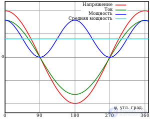
The sinusoidal voltage (red line) and current (green line) are in phase, that is, the phase-shift angle φ=0° (cosφ=1) — the load is purely active, with no reactive component. The instantaneous power (blue line) and active power (light-blue line) are calculated with a power factor equal to 1. As can be seen, the blue line (the instantaneous power graph) lies entirely above the x-axis (in the positive half-plane); all the delivered energy is converted into work, becoming active power consumed by the load
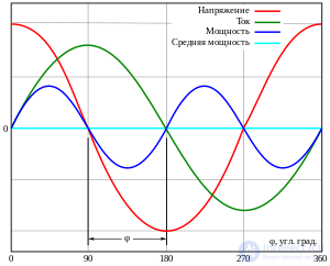
The sinusoidal voltage (red line) and current (green line) have a phase shift φ of 90° (cosφ =0) — the load is fully reactive, with no active component. The instantaneous power (blue line) and the active power (light blue line) are calculated with a power factor equal to 0. The position of the blue line (the instantaneous power graph) on the x-axis shows that during the first quarter of the cycle all the incoming power is temporarily stored in the load, and during the second quarter of the cycle it is returned to the grid, and so on, i.e. no active power is consumed and no useful work is done in the load
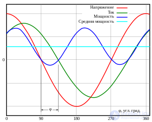
The sinusoidal voltage (red line) and current (green line) have a phase shift φ of 45° (cosφ=0.71) — the load has both an active and a reactive component. The instantaneous power (blue line) and the active power (light blue line) are calculated from the alternating voltage and current with a power factor equal to 0.71. The position of the blue line (the instantaneous power graph) below the x-axis shows that some part of the incoming power is still returned to the grid during the part of the cycle marked φ
It can be shown that if a load is connected to a sinusoidal voltage source (for example, a ~230 V, 50 Hz outlet) in which the current leads or lags the voltage in phase by some angle, then increased power is dissipated in the source's internal active resistance. In practice, this means that when a power plant supplies a load with a reactive component, more heat removal is required than when supplying an active load; the excess of the transmitted energy is released as heat in the wires, and on the scale of, for example, an industrial plant, the losses can be quite significant.
The power factor (English "Power Factor") should not be confused with the efficiency (coefficient of performance) of a load. The power factor has practically no effect on the energy consumption of the device itself that is connected to the mains, but it does affect the energy losses in the wires leading to it, as well as at the points of energy generation or conversion (for example, at substations). That is, an electricity meter in an apartment will practically not respond to the power factor of devices, since only the electricity that does work (the active component of the load) is billed. At the same time, the active power consumed by an electrical appliance directly depends on its efficiency. For example, a compact fluorescent («energy-saving») lamp consumes about 1.5 times more energy than an LED lamp of similar brightness. This is due to the higher efficiency of the latter. However, regardless of this, each of these lamps can have either a low or a high power factor, which is determined by the circuit design solutions used.

Power triangle
The power factor must be taken into account when designing electrical networks. A low power factor leads to an increase in the share of electrical energy losses in the network within the total losses. If its reduction is caused by a nonlinear, and especially a pulsed, nature of the load, this additionally leads to distortion of the voltage waveform in the network. To increase the power factor, compensating devices are used. An incorrectly calculated power factor can lead to excessive electricity consumption and a reduction in the efficiency of the electrical equipment supplied from that network.
For calculations in the case of harmonic variables  (voltage) and
  (current), the following mathematical formulas are used:




Here  — is the active power,
  — is the apparent power,
  — is the reactive power,
  — is the distortion power.
| Power factor value |
High | Good | Satisfactory | Low | Unsatisfactory |
|---|---|---|---|---|---|
| |
0,95…1 | 0,8…0,95 | 0,65…0,8 | 0,5…0,65 | 0…0,5 |
| |
95…100 % | 80…95 % | 65…80 % | 50…65 % | 0…50 % |
For the same active load power, the power uselessly dissipated in the wires is inversely proportional to the square of the power factor. Thus, the lower the power factor, the lower the quality of power consumption. To improve the quality of power consumption, various methods of power factor correction ("Power Factor Correction", "PFC") are used, that is, raising it to a value close to unity.
For example, most old luminaires with fluorescent lamps use electromagnetic ballasts (magnetic ballasts) for ignition and maintaining the discharge, which are characterized by a low power factor value, that is, inefficient power consumption. Many compact fluorescent («energy-saving») lamps with electronic ballasts are also characterized by a low power factor (0,5…0,65). But similar products from well-known manufacturers, like most modern luminaires, contain power factor correction circuits, and for them the value is close to 1, that is, to the ideal value.
Low quality of electricity consumption, associated with the presence of distortion power in the load, that is, a nonlinear load (especially of a pulsed nature), leads to distortion of the sinusoidal shape of the supply voltage. Non-sinusoidality is a type of nonlinear voltage distortion in an electrical network, associated with the appearance in the voltage of harmonics with frequencies many times higher than the network's fundamental frequency. Higher voltage harmonics have a negative effect on the operation of the power supply system, causing additional active losses in transformers, electrical machines and networks, and an increased fault rate in cable networks.
The sources of higher current and voltage harmonics are electrical loads with nonlinear characteristics. For example, high-power AC rectifiers used in the metallurgical industry and railway transport, gas-discharge lamps, switched-mode power supplies, and others.
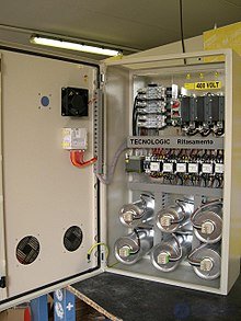
Power factor correction using capacitors
Power factor correction (PFC) is the process of bringing the consumption of an end device, which has a low power factor when powered from an AC power network, into a state in which the power factor complies with accepted standards.
Non-resistive loads — reactive and nonlinear — lead to a degradation of the power factor (a change in the consumed current disproportionate to the applied voltage). Reactive loads are corrected by external reactances, and it is precisely for them that the value  is defined. Correction of a nonlinear load is technically implemented in the form of one or another additional circuit at the input of the device.
This procedure is necessary for the uniform use of phase power and to prevent overloading of the neutral conductor in a three-phase network. Thus, power factor correction is recommended for sufficiently powerful switched-mode power supplies. Compensation ensures the absence of current consumption spikes at the peak of the supply voltage sine wave, which is characteristic of circuits where the input has a diode bridge and a smoothing capacitor, and, as a result, a more uniform load on the power line.

Comments