
Lecture
Это окончание невероятной информации про элементы тракта свч.
...
Microwave Loads, Microwave Power Dividers" > , we write the scattering matrix of the polarizer with respect to the parallel- and perpendicular-polarization waves:
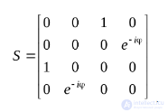 .
.
It follows that the input and output terminal pairs of the eight-terminal network are matched and decoupled. In addition, s41 = s32 = s23 = s14 = 0, since waves of orthogonal polarization propagate along the waveguide independently of each other, i.e., no exchange of energy between them occurs during their propagation.
Let us consider the passage through such a polarizer of an H11 wave whose E vector is directed along the y axis. This wave can be represented as a linear combination of perpendicular- and parallel-polarization waves with amplitudes a﬩ and a|| respectively. Setting the amplitude of the H11 wave to unity and using Fig. 3.33, a), we obtain a﬩ = cosΨ; a|| = sinΨ. Then the column of incident waves a can be written as  . Using the relation b = Sa, we obtain for the column of reflected waves
  . It follows that the phase of the parallel-polarization wave has changed at the output of the polarizer. By choosing the plate dimensions so that φ = 90°, and orienting it at an angle Ψ = 45°, we obtain a circularly polarized wave at the output of such a polarizer. Indeed, at the output of the polarizer
  , , i.e., the wave has orthogonal components of equal amplitude, shifted in phase relative to each other by – 90°. The E vector of such a wave rotates counterclockwise when viewed in the direction of wave propagation. By similar reasoning, it can be shown that when the polarizer is excited by an H11 wave whose E vector is parallel to the x axis, the output is an H11 wave with circular polarization of the opposite rotation. It should be noted that instead of a dielectric plate, two metal ridges located in the same plane as the plate can be provided on the walls of the circular waveguide. The action of these ridges is equivalent to the action of the plate.
Microwave polarizers can also be implemented based on the use of the Faraday effect in a longitudinally magnetized ferrite (Fig. 3.34). It consists of a circular waveguide carrying the H11 wave, on whose axis a ferrite rod is placed. The constant magnetizing field is created by a solenoid wound directly on the waveguide. The magnitude of this field is chosen so that the magnetic permeabilities of the ferrite for right- and left-hand circularly polarized waves are different. It is known that a linearly polarized wave can be represented as the sum of circularly polarized waves of opposite rotation. Then, exciting the input of the polarizer under consideration with an H11 wave whose E vector is parallel to the y axis (Fig. 3.35), we decompose it into two waves of right and left rotation.
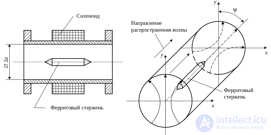
Fig. 3.34 Ferrite polarizer based on the Faraday effect Fig. 3.35 Rotation of the plane of polarization of the H11 wave in a circular waveguide with a longitudinally magnetized ferrite
Due to the difference in the magnetic permeabilities of the ferrite for these waves, they have different phase velocities in the ferrite-loaded waveguide. Therefore, as the waves propagate along the waveguide, a phase shift develops between them, the magnitude of which is determined by the length of the rod. This phase shift determines the rotation, by an angle Ψ, of the plane of polarization of the H11 wave formed by the addition of these two circularly polarized waves at the output of the polarizer. The microwave polarizers considered are used both independently to change the polarization of the passing wave and as an element of complex microwave devices.
The use of ferrites at microwave frequencies is due to the specifics of radio wave propagation in them. Theoretical aspects of this issue are considered in the discipline «Electrodynamics and Radio Wave Propagation». Let us briefly consider the effects occurring in magnetized ferrites when microwave electromagnetic waves propagate in them.
Basic properties of ferrites at microwave frequencies. A ferrite is a type of magnetic ceramic with εr = 8…16 and tgδ = 10-2…10-3. The magnetic permeability of ferrite in the microwave range is determined by the gyromagnetic properties of electrons. As it rotates about its own axis, an electron, having mass and charge, creates mechanical Re and magnetic Me moments directed in opposite directions (Fig. 3.36). Regions of the ferrite in which the magnetic moments of most electrons are oriented in the same direction are called domains. The volume of a single domain is approximately 10-12 cm3. Due to their random orientation in the ferrite, the resulting magnetic moment is zero.
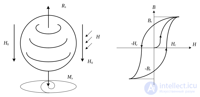
Fig. 3.36 Electron in a magnetic field Fig. 3.37 Hysteresis loop
In a constant magnetic field H0 the electron's rotation axis orients itself along the direction of this field. Therefore the magnetic moments of the individual domains become uniformly oriented and form the resultant magnetic moment of the magnetized ferrite. A magnetized ferrite is characterized by: the magnetization vector M, defined as the limit of the ratio of the ferrite's resultant magnetic moment to its volume as the latter tends to zero; the permeability tensor ||μ|| and the magnetic induction vector B = μ0(H + M) = ||μ||H. As the constant magnetic field strength H0 increases, the domains reorient, and the resultant magnetic moment and magnetic induction of the ferrite grow. This continues until the vectors H0 and M become parallel. With a further increase in H0, the electrons not yet oriented within the domains align with the field, after which the ferrite saturates. As H0 decreases, the magnetic induction decreases. However, the law governing this decrease does not coincide with the law of its increase. This is called the hysteresis phenomenon (Fig. 3.37). The hysteresis loop is characterized by the saturation induction Bs, the remanent magnetization Br, and the coercive force Hc. Remanent magnetization is used in phase shifters based on rectangular-loop ferrites to provide internal memory.
When the rotation axis of an electron located in a constant magnetic field is deflected by some external force, it begins to precess (rotate) about the direction of stable equilibrium. Precession always occurs clockwise when viewed in the direction of H0. In the presence of losses, precession follows a spiral converging toward the direction of H0 (see Fig. 3.36). The role of the external force deflecting the electron's rotation as a radio wave propagates through the ferrite is played by the alternating magnetic field of that wave. Thus the whole variety of ferrite properties during radio-wave propagation through it is determined by the magnitude and mutual orientation of the constant magnetizing field H0 and the high-frequency field H. From electrodynamics it is known that in a ferrite magnetized by a field H0 oriented along the z axis, the magnetic induction B and the magnetic field H are related by:
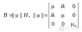 .
.
In expanded form this relation is:
 ,
,
where μ, k are the complex elements of the permeability tensor, which depend on H0 and the frequency ω; μ0 = 4π10-7 H/m is the absolute magnetic permeability. It follows that if the high-frequency field vector H is parallel to the z axis, i.e. Hx = Hy = 0, Hz = H, then the magnetic induction vector has only a single component Bz = μ0H, and the gyromagnetic properties of the ferrite do not manifest themselves. If, however, the magnetic field vector H has circular polarization, and the plane of rotation is perpendicular to the magnetizing field, then the magnetic induction vector also has circular polarization, coinciding in direction with the vector H. Indeed, let us set H = x0H ± iy0H, where x0, y0 are unit vectors of a rectangular coordinate system; the lower sign corresponds to right-hand circular polarization (clockwise when viewed in the direction of H0), and the upper sign to left-hand rotation (counterclockwise when viewed in the direction of H0). Let us find Bx, By, and Bz:
 – for right-hand rotation;
 – for left-hand rotation;
In these expressions μ+ and μ– –are the complex magnetic permeabilities of the ferrite for right- and left-hand circularly polarized waves, respectively. Thus, knowing the direction and magnitude of the constant magnetizing field H0, computing the real and imaginary parts of μ+ and μ–, and representing the high-frequency field H as a linear combination of right- and left-hand circularly polarized fields, one can find the values of Bx and By and establish the gyromagnetic effects occurring in the ferrite. Fig. 3.38 shows the dependence of 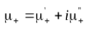 and μ– on the magnitude of the magnetizing field when the frequency ω coincides with the electron precession frequency.
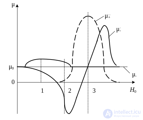
Fig. 3.38 Dependence of the ferrite's magnetic permeability for circularly polarized magnetic-field waves on the magnitude of the magnetizing field
The Faraday effect occurs when a linearly polarized electromagnetic wave propagates through a ferrite in the direction of the magnetizing field (see Fig. 3.35). It manifests itself as a rotation of the plane of polarization of this wave by some angle Ψ upon passing through a longitudinally magnetized ferrite. In this case the magnitude of the magnetizing field H0 must correspond to point 1 in Fig. 3.38. At this point, the real parts of the ferrite's magnetic permeabilities for right-hand  and left-hand
  circularly polarized waves differ, with
  . A linearly polarized wave can be represented as a combination of equal-amplitude right- and left-hand rotating waves. Because the magnetic permeabilities of these waves differ, they have different phase velocities in the ferrite
  and acquire different phase shifts when propagating over the same distance. Therefore the linearly polarized vector, formed by summing the fields of the right- and left-hand rotating waves, rotates by some angle Ψ, proportional to the difference in the phase coefficients of these waves. The rotation of the polarization plane always occurs clockwise when viewed in the direction of the magnetizing field vector H0 and does not depend on the direction of wave propagation, i.e. the Faraday effect is a nonreciprocal effect.
The field-displacement effect occurs when waves propagate across the magnetizing field H0, with the vector H of the propagating wave having right-hand circular polarization in the plane perpendicular to H0 (Fig. 3.39).
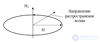
Fig. 3.39 Orientation of the vectors H0 and H under transverse ferromagnetic resonance
In this case the magnitude of the magnetizing field H0 must correspond to point 2 in Fig. 3.38. At this point the real part of the ferrite's magnetic permeability for right-hand rotating waves is negative, which corresponds to an imaginary value of the wave's phase coefficient. Therefore such a wave does not propagate in the ferrite, and the field is displaced out of the ferrite. Meanwhile the left-hand rotating wave propagates through such a ferrite as through an ordinary dielectric with elevated permittivity and permeability values. When the direction of rotation of the vector H changes. Therefore the field-displacement effect is a nonreciprocal effect.
The ferromagnetic-resonance effect occurs under the same conditions as the field-displacement effect. The difference lies only in the magnitude of the magnetizing field, which must correspond to point 3 in Fig. 3.38. At this point the imaginary part of the ferrite's magnetic permeability for the right-hand rotating wave has a resonant value, which determines large heat losses. These losses arise because the energy of the wave's high-frequency field is spent maintaining the precession of electrons in the ferrite, since the direction of rotation of the vector H of this wave coincides with the direction of precession, and the frequency of the electromagnetic oscillations coincides with the electron precession frequency. Like the field-displacement effect, transverse ferromagnetic resonance is a nonreciprocal effect.
Microwave isolators. An isolator is a microwave device that passes power from input to output in the forward direction without loss and completely absorbs the microwave power applied to its output. In an equivalent circuit the isolator is represented as a nonreciprocal two-port network (Fig. 3.40) and has a scattering matrix of the form:
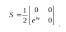
where φ is the phase shift introduced by the isolator as the wave passes from input 1 to input 2.
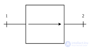
Fig. 3.40 Schematic symbol of an isolator
It can be seen that the isolator's scattering matrix is nonsymmetric and non-unitary. Consequently, the isolator is a lossy nonreciprocal microwave device. The most widely used in practice are resonance isolators, field-displacement isolators, and polarization isolators.
A resonance isolator in a rectangular waveguide carrying the H10 wave (Fig. 3.41) consists of a ferrite plate 1 placed parallel to the longitudinal axis of the waveguide at a distance from its narrow wall where the amplitudes of the longitudinal and transverse components of the magnetic field are equal. In this cross-section the magnetic field vector rotates in the H plane in the direction set by the direction of wave propagation.
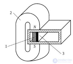
Fig. 3.41 Rectangular-waveguide isolator
The transverse magnetizing field H0 is created by a permanent magnet 2. The operation of such an isolator is based on the ferromagnetic-resonance effect. For the incident wave, at the location of the ferrite the magnetic field vector rotates counterclockwise, which corresponds to a left-hand rotating wave. Such a wave propagates through the ferrite-loaded waveguide practically without loss. The reflected wave, at the location of the ferrite, has a right-hand rotating magnetic field vector and is intensely absorbed by the ferrite. Dielectric plate 3 is intended to widen the isolator's operating frequency band. A drawback of the resonance isolator is the large magnetizing field strength H0 required and, consequently, the large weight of the permanent magnet and of the isolator itself.
This drawback is largely eliminated in isolators built on the basis of the field-displacement effect. Structurally it is built the same way as the resonance isolator. The difference is that instead of the dielectric plate 3 (see Fig. 3.41), the side surface of the ferrite is coated with a radio-absorbing film. The location of the ferrite plate is chosen so that, for the incident wave, it corresponds to right-hand rotation of the vector H. In this case the ferrite's magnetic permeability is negative, the phase coefficient in the ferrite becomes purely imaginary, and the wave field is displaced out of the ferrite (Fig. 3.42).
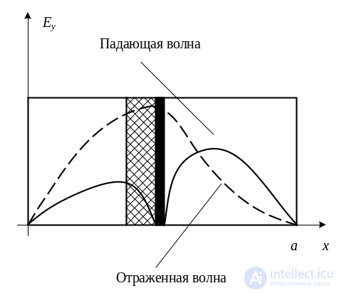
Fig. 3.42 Distribution of the transverse electric field in the waveguide of a field-displacement isolator
The wave propagates through the waveguide practically without loss, since at the location of the absorbing film a null of the transverse electric field forms. The reflected wave, at the location of the ferrite, has a positive magnetic permeability. For this wave, at the location of the absorbing film, a maximum of the transverse electric field component forms, and it is intensely absorbed by this film.
A polarization isolator (Fig. 3.43, a) consists of a polarizer carrying the H11 wave (see Fig. 3.34), whose principle of operation was discussed earlier and is based on the use of the Faraday effect. Smooth transitions 1ˊ and 2, which serve as the isolator's input and output, are connected to the polarizer's ports. Absorbing plates 3ˊ are placed inside the transitions. The parameters of ferrite rod 1ˊ and solenoid 4ˊ are chosen so as to provide a rotation of the polarization plane, propagating through the circular waveguide as the H11 wave, by an angle Ψ = 45°.
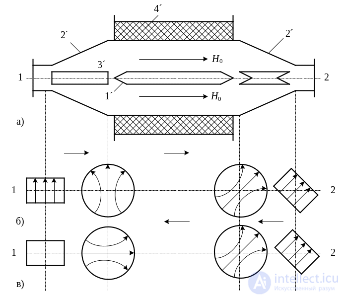
Fig. 3.43 Polarization isolator
When isolator input 1 is excited by the H10 wave of the rectangular waveguide (Fig. 3.43, b), it is converted in smooth transition 2ˊ into the H11 wave of the circular waveguide. This conversion occurs without absorption of microwave power by plate 3ˊ, since the electric field lines of the passing wave are perpendicular to the plate. After passing through the polarizer, the polarization plane of the H11 wave rotates clockwise by 45°, and the electric field lines become parallel to the narrow walls of the output rectangular waveguide. The second smooth transition converts, without loss, the circular waveguide's H11 wave into the H10 wave of rectangular waveguide 2. When the latter is excited by the H10 wave (Fig. 3.43, c), it is converted, without loss, into the H11 wave of the circular waveguide. After passing through the polarizer, the polarization plane of the H11 wave rotates clockwise by 45°, since the direction of rotation of the polarization plane in the Faraday effect is determined by the direction of the magnetizing field H0 and does not depend on the direction of wave propagation. Thus the electric field lines of the H11 wave become parallel to the absorbing plate and to the wide walls of rectangular waveguide 1. The microwave power carried by this wave is intensely absorbed by plate 3ˊ, and the wave does not reach input 1ˊ.
Isolators are used as decoupling elements in microwave paths, for example to eliminate the harmful effect of a reflected wave on a microwave oscillator.
Microwave circulators. Circulators are microwave devices having three or four input transmission lines (Fig. 3.44), where microwave power is transmitted without loss in one direction, for example, from input 1 to input 2, from input 2 to input 3, and so on.
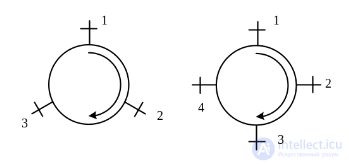
Fig. 3.44 Schematic symbols of circulators:
a – Y-circulator, b – X-circulator
Circulators with three input transmission lines are called Y-circulators. Circulators with four inputs are called X-circulators. In an equivalent circuit such circulators are represented as a six-port or eight-port network, respectively, and have scattering matrices:
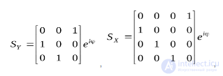
where φ is the phase shift introduced by the circulator as the wave passes from one input to another. It can be seen that the scattering matrices of circulators are nonsymmetric but unitary. Consequently, a circulator is a lossless nonreciprocal microwave device. The most practically widespread are Y-circulators, which use the difference in the ferrite's magnetic permeabilities for right- and left-hand circularly polarized field waves, as well as polarization and phase X-circulators.
A waveguide Y-circulator (Fig. 3.45) is built on the basis of an H-plane Y-junction, on whose axis a ferrite disk 1ˊ and a dielectric ring 2ˊ are placed. Permanent magnets are placed above and below the ferrite disk (not shown in Fig. 3.45). Dielectric posts 3ˊ are intended for matching the circulator's inputs.
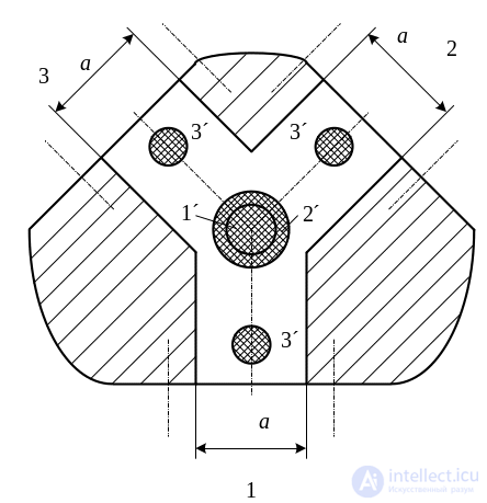
Fig. 3.45 Waveguide Y-circulator
The dielectric ring is intended to increase the temperature stability and the robustness of the Y-circulator's characteristics against changes in the magnetizing field. When, for example, input 1 is excited by the H10 wave of the rectangular waveguide, it splits into two waves that wrap around the ferrite disk. The directions of rotation of the vector H of these waves at the location of the ferrite turn out to be opposite. Therefore the ferrite's magnetic permeabilities for these waves, μ+ and μ–, turn out to be different. This causes a difference in the phase velocities of the waves wrapping around the ferrite disk from different sides. The dimensions and parameters of the ferrite are chosen such that these waves add in phase at input 2 of the circulator, and are in antiphase at input 3. Because of the rotational symmetry of the Y-circulator, analogous processes occur when inputs 2 and 3 are excited.
A polarization circulator (Fig. 3.46, a) has a design analogous to the polarization isolator (see Fig. 3.43). The difference is that the absorbing plates are replaced by waveguide inputs 3 and 4 of the circulator. Moreover, input 4 is rotated relative to input 3 by 45° clockwise, when viewed in the direction of the field H0. Fig. 3.46, b), c), d), and e) schematically show the mutual arrangement and field structure in various cross-sections when each of its inputs is excited. When input 1 is excited, microwave power passes to input 2 in the same way as in the polarization isolator. Inputs 3 and 4 turn out to be decoupled, since with the orientation of the field lines shown in Fig. 3.46, b), E-waves are excited in them, which are in a cutoff regime. When input 2 is excited, microwave power is transmitted to input 3, since after passing through the polarizer the polarization plane of the H11 wave rotates 45° clockwise, and the electric field lines become perpendicular to the wide walls of the waveguide at input 3. In this case inputs 1 and 4 turn out to be decoupled, since the fundamental H10 wave is not excited in them. The transmission from input 3 to input 4 and from input 4 to input 1 is explained analogously (Fig. 3.46, d) and e) respectively).
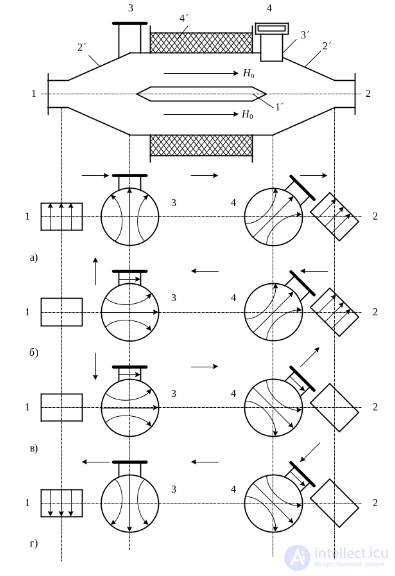
Fig. 3.46 Circulator based on a circular waveguide:
1ˊ – ferrite rod; 2ˊ – transition from circular to rectangular waveguide; 3ˊ – side branches to the rectangular waveguide; 4ˊ – solenoid
The phase circulator is an X-circulator, and its diagram is shown in Fig. 3.47.
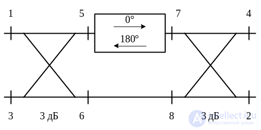
Fig. 3.47 Diagram of a phase circulator
It consists of two, for example, waveguide slot-hybrid bridges, between which a nonreciprocal phase shifter is connected. When a wave passes through such a phase shifter in the forward direction, its phase does not change, while on the return pass it changes by 180°.
Such a phase shifter in a rectangular waveguide is made in the form of a transversely magnetized ferrite plate, positioned parallel to the waveguide axis at the location of circular polarization of the magnetic field of the H10 wave. Counter-propagating waves in the waveguide have opposite directions of rotation of the H vector at the location of the ferrite plate. Therefore, due to the different values of the magnetic permeabilities μ+ and μ–, they acquire different phase shifts. When input 1 of the phase circulator is excited, the power is divided equally between arms 5 and 6 of the bridge. Moreover, the phase of the wave in arm 5 is φ5 = 0°, and in arm 6 it is φ6 = – 90°. The phase relations in arms 7 and 8 of the second bridge are preserved, i.e., the phases of the waves exciting these arms of the bridge are φ7 = φ5 = 0°, φ8 = φ6 = – 90°, since the nonreciprocal phase shifter does not change the phase of the passing wave. The second bridge divides the power fed to each of arms 7 and 8 equally between circulator inputs 4 and 2. In this case, at input 4 the waves add in antiphase, while at input 2 they add in phase. Thus, when input 1 of the circulator is excited, the microwave power is transferred to input 2. When input 2 of the circulator is excited, the power is divided by the bridge equally between arms 7 and 8, with φ7 = – 90°, φ8 = 0°. Upon passing through the nonreciprocal phase shifter from arm 7 to arm 5, the wave's phase changes and becomes φ7 = φ5 = – 270°, and in arm φ8 = φ6 = 0°. When arms 5 and 6 of the bridge are excited by equal-amplitude waves with such phases, their in-phase addition occurs at input 3 of the circulator. At input 1 they turn out to be in antiphase. Reasoning similarly for the excitation of inputs 3 and 4 of the circulator, it can be shown that the microwave power is transferred to inputs 4 and 1, respectively.
The practical implementation of such circulators is determined by the design of the bridge device, which can be made in the form of waveguide slot-hybrid bridges, a double T-bridge, a ring bridge, and the like.
Circulators are used in the paths of transmit-receive radio systems for operating on receive and transmit using a common antenna. They are also used in circuits for summing the power of several microwave generators and in the paths of microwave test benches.
It should be noted that, in addition to the microwave devices considered that use ferrites (phase shifters, isolators, circulators), there are also control devices based on ferrites in the form of switches, commutators, attenuators, controlled power dividers, tunable filters, and the like. Their operation is based on changing the current in the control windings. The operating principle and design of such devices are described in specialized literature.
Часть 1 3. Elements of the Microwave Path, Microwave Loads, Microwave Power Dividers
Часть 2 3.4 Microwave devices using ferrites - 3. Elements of the

Comments