
Lecture
M-Bus (Meter-Bus) — a physical-layer standard for a field bus based on an asynchronous interface. The same name is also used for the communication protocol used to connect devices over this bus.
M-Bus is mainly used for electrical energy meters (electricity meters), thermal energy meters (heat meters), and water and gas flow meters. Data is transmitted to a computer station (server) either directly or through M-Bus concentrators, as well as signal amplifier-repeaters.
The bus is half-duplex, with permissible data rates of 300-9600 bit/s (compatible with the standard rates of UART ports on PCs and microcontrollers, which are the source and receiver of the data). Recommended cable type: standard telephone cable (JYStY N*2*0.8 mm). Line capacitance per unit length should not exceed 180 nF, with resistance up to 29 ohms. Operating range in the standard configuration is up to 1000 m. The range from a slave device to the signal repeater is up to 350 m. The number of devices on the network is up to 250.
The master transmits data by changing the voltage on the line: logic «1» corresponds to 36 V, logic «0» to 12..24 V. The slave device transmits data by loading the line: in the passive state (logic «1»), the load current on the communication line must not exceed 1.5 mA and must not change in the absence of transmission. To transmit logic «0», the slave device increases its current draw to 11..20 mA. Accordingly, the master tracks the change in load current, treating unchanged current as logic «1» and an increase in current draw as logic «0».
Since the physical layer is network-based, several slave devices can be connected to a single pair of wires (up to 250 per the standard). This means the total current draw of the bus from the master can reach up to 250 * 1.5 mA + 20 mA = 400 mA. The standard allows a single slave to occupy up to 4 unit loads, i.e. up to 6 mA.
Integrated M-Bus AFE implementations exist for slave devices. Examples include the Texas Instruments TSS721, and the ON Semiconductor NCN5150 and NCN5151.
The standard does not define the types of electrical connectors (plugs).
The M-Bus was originally described in the European heat-meter standard EN1434-3 «Heat meters. Part 3: Data exchange and interfaces» and its Russian equivalent GOST R EN 1434-3 «Heat meters. Part 3: Data exchange and interfaces». Later M-Bus was also standardized in EN13757 «Communication systems for meters and remote reading of meters».
The protocol part of M-Bus can be used not only over the wired M-Bus physical layer, but also over other physical layers. Standardized options include the optical physical layer (per EN 62056-21 4.1), radio channel (868 MHz, EN 13757-4), current loop (EN 62056-21 3.1), and an alternative wired physical layer (per EN 13757-6).
| OSI layer | Standard |
|---|---|
| Application layer | EN1434-3 EN13757-3 |
| Presentation layer | None |
| Session layer | None |
| Transport layer | None |
| Network layer | Optional |
| Data link layer | EN1434-3 EN13757-2 |
| Physical layer | EN1434-3 EN13757-2 |
Open Metering System — a European initiative aimed at unifying data collection from resource meters based on the M-Bus. In addition to a number of simplifications and documentation improvements, it proposes introducing cryptographic data protection using the symmetric AES cipher. The OMS specifications are open.
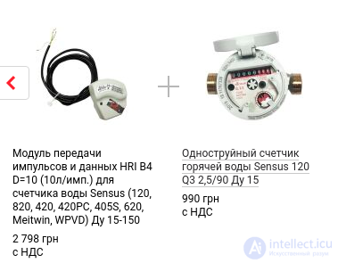
HRI is a universal sensor compatible with many types of water meters, such as single-jet and multi-jet, volumetric and piston, dry-dial and wet-dial water meters. The HRI module can be installed on any Sensus-manufactured meter that is fitted with a special HRI modulator, providing contactless (inductive) transmission of the impeller's rotations to the module.
The HRI-B DataUnit data transmission module is an electronic module with a digital interface that has all the capabilities of the PulseUnit pulse module, and can additionally be connected directly to an M-Bus network or to devices with a MiniBus interface. The customer can change the pulse value using dedicated software.
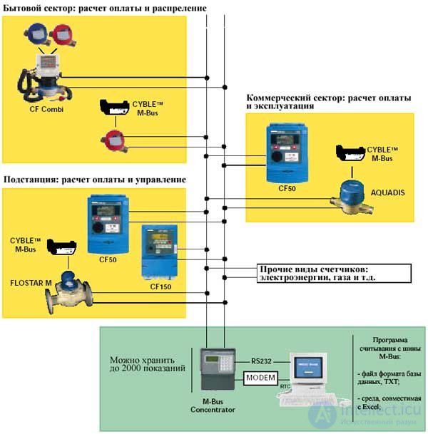
Principle of operation
M-Bus is a hierarchical system whose communication is controlled by a master (the central distribution logic). M-Bus consists of a master device, a number of slave devices (end-equipment meters), and a two-wire connecting cable: see Figure 8. Slave devices are connected in parallel to the transmission medium — the connecting cable.
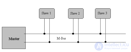
Fig. 8 Block diagram showing the principle of operation of the M-Bus system.
To implement a branched bus network with a low-cost transmission medium, a two-conductor cable was used together with serial data transmission. To allow remote powering of the slave devices, bits on the bus are represented as follows:
Bits are transmitted from master to slave by means of voltage-level shifts. Logic «1» (Mark) corresponds to a nominal voltage of +36 V at the output of the bus driver (repeater), which is part of the master; when sending logic «0» (Space), the repeater lowers the bus voltage by 12 V to a nominal +24 V at its output.
Bits sent in the direction from slave to master are encoded by modulating the current draw of the slave device. Logic «1» is represented by a constant current (dependent on voltage, temperature, and time) of up to 1.5 mA, while logic «0» (Space) is represented by the slave device's increased current draw of an additional 11-20 mA. The Mark-state current can be used to power the interface and, potentially, the meter or sensor itself.
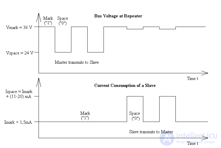
Fig. 9 Representation of bits on the M-Bus
Transmission of a Space by a slave device causes a slight drop in bus voltage at the repeater due to output resistance, as shown in Figure 9.
The idle state on the bus is logic «1» (Mark), meaning the bus voltage is 36 V at the repeater, and the slave devices each require a maximum steady quiescent current of 1.5 mA.
When no slave device is sending a Space, a constant current will be drawn from the repeater that drives the bus. As a result of this, as well as the cable resistance, the actual Mark voltage at the slave devices will be lower than +36 V, depending on the distance between the slave device and the repeater and on the total quiescent current of the slave devices. Therefore the slave device must not detect absolute voltage levels, but instead must detect a 12 V voltage drop for a Space. The repeater must itself adapt to the quiescent (Mark) current level and interpret an increase in bus current of 11-20 mA as representing a Space. This can be implemented with acceptable complexity only when the Mark state is defined as 36 V. This means that at any given moment, transmission is possible in only one direction — either from master to slave or from slave to master (half-duplex).
As a result of transmission in the master-to-slave direction with a voltage change of 12 V, and in the response direction of at least 11 mA, a high degree of immunity to external interference was achieved in addition to remote powering of the slave devices.
Specifications for installation on the BUS
Segmentation
An M-Bus system can consist of several so-called zones, each having its own group address and interconnected via zone controllers and higher-level networks. Each zone consists of segments, which in turn are connected by remote repeaters. However, an M-Bus system typically consists of only a single segment, which is connected via a local repeater to a personal computer (PC) acting as the master. Such local repeaters convert M-Bus signals into signals for an RS232 interface. From this point on, the local repeater will simply be referred to as the «repeater», and the combination of the PC and the local repeater will be referred to as the «master».
Cable
A standard two-conductor telephone cable (JYStY N * 2 * 0.8 mm) is used as the transmission medium for M-Bus. The maximum distance between a slave device and the repeater is 350 m; this length corresponds to a cable resistance of up to 29 Ω. This distance applies to the standard configuration with a baud rate of 300 to 9600 baud and a maximum of 250 slave devices. The maximum distance can be increased by limiting the baud rate and using fewer slave devices, but the bus voltage in the Space state must not drop below 12 V at any point in the segment, due to the remote powering of the slave devices. In the standard configuration, the total cable length must not exceed 1000 m, in order to meet the maximum cable capacitance requirement of 180 nF.
Connector
There is not yet a standard or recommendation for an M-Bus connector for connecting meters to the bus system, but a user group is investigating the correct connector. Three different plugs need to be defined for the connector: a) the installation mode; b) from the meter to a fixed installation; and c) from the meter to a portable device.
4.4 Slave design
The requirements for slave devices are listed in the specification document. They include the following characteristics:
· Transmission characteristics
Slave devices are designed as DC receivers with two different currents, where the «flooded» current must not change by more than 0.2% when the bus voltage changes by 1 V. For transmitting a Mark, a so-called unit load is specified, consisting of a maximum steady current of 1.5 mA. If a slave device requires more current, the corresponding number of additional unit loads must be used. When sending a Space, the slave increases its current draw by 11-20 mA. To receive data, the slave device determines the maximum voltage value Vmax on the bus, which can range from 21 V to 42 V. At a bus voltage above Vmax - 5.5 V, a Mark must be registered, and at a voltage below Vmax - 8.2 V, a Space must be registered.
· Remote power supply
The bus interface, i.e. the interface between the slave device and the bus system, must draw the current it needs from the bus system. If possible, the entire slave should be powered from the bus; in this case, if the bus fails, it must automatically switch to battery operation, or important data must be saved. If slave devices operate solely on batteries, the battery life must be several years in order to reduce maintenance costs.
· Protective measures
The bus interfaces of slave devices are polarity-independent: that is, the two bus lines can be swapped without affecting the operation of the slave devices. Besides protection aspects, this also simplifies installation of the bus system. To maintain correct bus operation in the event of a short circuit at one of the mentioned slave devices, they must have a protective resistor rated at (430 ± 10) Ω on their bus lines. This limits the current in the event of a short circuit to 100 mA (42 V / 420 Ω) and reduces the energy converted to heat in the bus interface.
TSS721 M-Bus transceiver
To meet the requirements for slave devices mentioned above, Texas Instruments Deutschland GmbH developed an IC, namely the TSS721 transceiver (i.e. transmitter and receiver). Using the TSS721 in M-Bus slave devices as the interface to the bus reduces the number of components required and, consequently, the cost of the slave devices. In addition to transmitting and receiving data in accordance with the M-Bus specification, this IC also converts the operating voltage of the microprocessor it is connected to, and back, so that it can communicate with it. Data exchange can occur at rates from 300 to 9600 baud. Additional features include built-in reverse-polarity protection, a constant 3.3 V power supply for the microprocessor, and fast indication of bus voltage failure.
Referring to Figure 10, the individual functions of the TSS721 will now be explained in more detail:
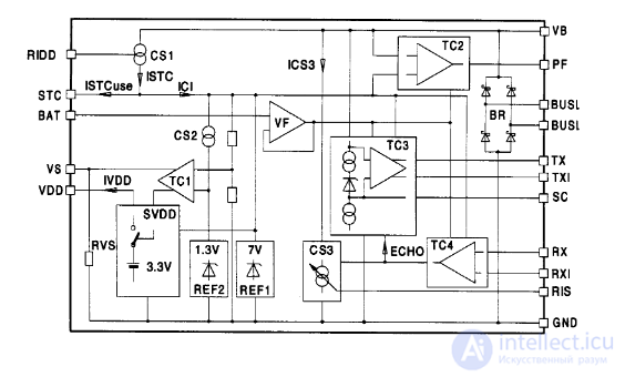
Fig. 10 Block diagram of the TSS721 transceiver
· Reverse-polarity protection
The bus lines are first connected to the BR bridge rectifier via external protective resistors Rv (in this case 215 Ω on each line) in order to provide reverse-polarity protection. This rectified voltage can be obtained at the VB (bus voltage) pin. To avoid a voltage drop resulting from rectification when reverse-polarity protection can be dispensed with, the bus voltage can also be connected directly between the VB and GND pins.
· Reception
The TC3 comparator circuit is designed to detect signals from the master device; it adapts to the Mark voltage level using the SC capacitor. This capacitor is charged to 8.6 V under Mark voltage in the Mark state, and discharges in the Space state. The ratio of charge current to discharge current is more than 30, so that any UART protocol will work regardless of the data content. The voltage on the SC capacitor causes the comparator to dynamically track the Mark level. From the relationship between the charge and discharge currents follows the requirement in the transmission protocol that at least every eleventh bit (with sufficient certainty) must be a logic 1, i.e. a Mark. This ensures that SC is not discharged too much and that matching to the Mark voltage level remains effective at all times.
· Transmission
The signal from the microprocessor, applied to the RX pin or the RXI (inverted) pin, is converted into current by TC4 and the CS3 constant-current source. When a Mark is present at the inputs (RX or RXI), the quiescent current is drawn from the bus via the constant-current source. However, if the processor transmits a Space, TC4 switches on the CS3 constant-current source and thus the additional pulse current. The quiescent current can be adjusted within a certain range using the Ridd resistor, and the pulse current using Ris. To allow the processor to detect collisions, the signal on the RX(I) pins is mirrored onto the TX(I) pins.
· Processor power supply
The TSS721 provides a nominal voltage of 3.3 V at its VDD pin to power the microprocessor. Limited to the standard load, according to the datasheet this processor can draw an average current of around 600 mA. A storage capacitor, STC, is used for pulse-current requirements. When connected to the bus, this capacitor is charged to 7 V, and power at the VDD pin is activated when V STC = 6 V. The TSS721 signals a bus voltage failure at the PF (power fail) pin, so that the processor has time to save its data, e.g. to EEPROM, while being powered from the storage capacitor. In addition, the transceiver allows a battery to be connected to the VDD pin in the event of bus failure, via a field-effect transistor at the VS (voltage switch) pin. In such a case, when the microprocessor is powered solely by the battery, voltage must also be applied to the BAT pin in order to comply with the TSS721.
Figure 11a) shows the three alternative operating modes of the TSS721 that can be used to power the microprocessor. This shows that the processor can be powered exclusively from the transceiver (remote power), normally from the TSS721 and, on bus failure, from a battery (remote power / battery backup), or from a battery alone. Building a complete slave device with the TSS721 requires only a few external components besides the microprocessor or microcontroller and the components specifically needed for the sensing elements. Figure 11b) also shows a basic optocoupler application.
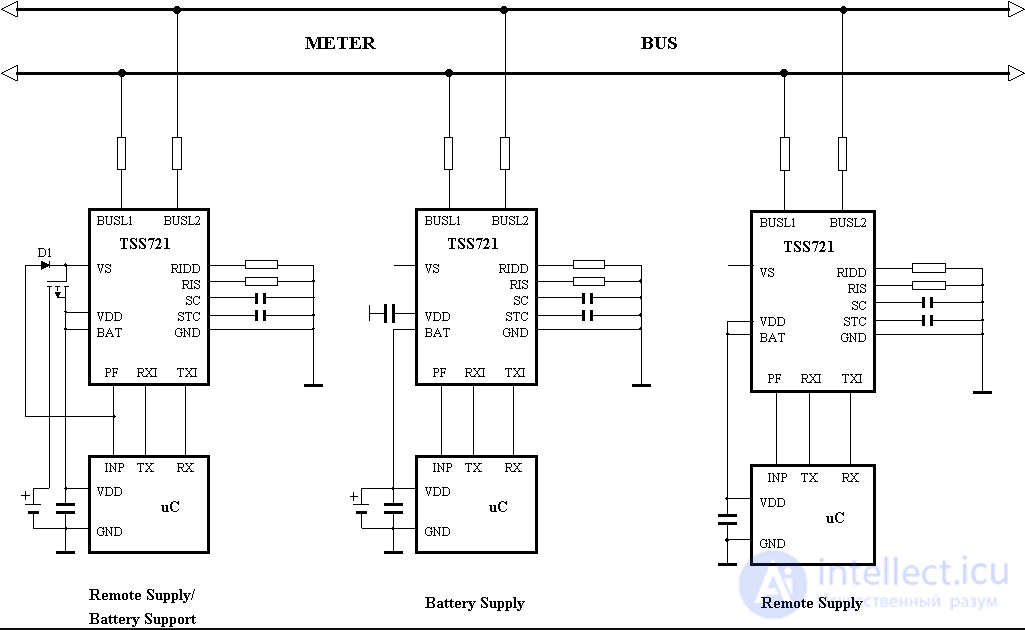
Fig. 11a) TSS721 operating modes for powering the microcontroller
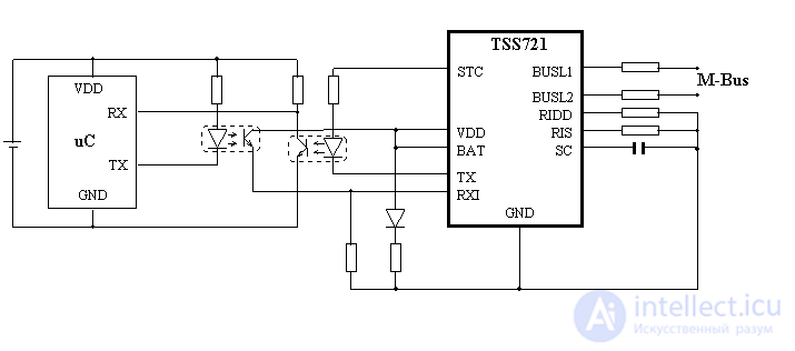
Fig. 11b) Basic optocoupler application

Comments