
Lecture
A fiber-optic cable , also known as an optical fiber cable , is an assembly similar to an electrical cable , but containing one or more optical fibers used to transmit light. Optical fiber elements are usually individually coated with plastic layers and enclosed in a protective tube suitable for the conditions in which the cable is used. Various cable types [ 1 ] are used for fiber-optic communication in various applications, for example for long-distance communication or to provide a high-speed data connection between different parts of a building.
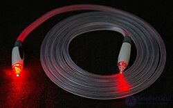
A TOSLINK optical cable with a transparent jacket. These cables are mainly used for digital audio connections between devices.
Glass optical fibers are made from fused silica, but for the far-infrared range other materials can be used, such as fluorozirconate, fluoroaluminate and chalcogenide glasses. Like other glasses, these have a refractive index of about 1.5.
The production of silica fibers goes through 2 stages:
The use of plastic optical fibers is currently developing. The core of such a fiber is made of polymethyl methacrylate (PMMA), and the cladding — of fluorinated PMMA (fluoropolymers).
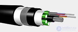
Multi-fiber cable
An optical fiber consists of a core and a cladding , chosen for total internal reflection due to the difference in refractive indices between them. In practical fibers, the cladding is usually covered with a layer of acrylate polymer or polyimide . This coating protects the fiber from damage but does not affect its optical waveguide properties. A durable buffer layer of resin or a core tube(s) is then extruded over the individual coated fibers (or fibers formed into ribbons or bundles) to form the cable core. Depending on the application, several layers of protective sheathing are added to form the cable. In rigid fiber-optic assemblies, light-absorbing («dark») glass is sometimes placed between the fibers to prevent light exiting one fiber from entering another. This reduces crosstalk between fibers or reduces glare in fiber-bundle imaging applications. [ 2 ]
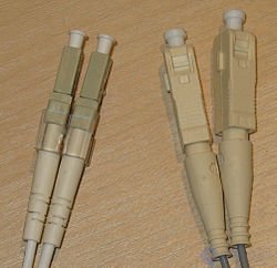
Left: LC/PC connectors.
Right: SC/PC connectors.
All four connectors have white caps covering the ferrules .
For indoor use, jacketed optical fiber is usually placed together with a bundle of flexible fibrous polymer elements, such as aramid (for example Twaron or Kevlar ), inside a lightweight plastic sheath to form a simple cable. Each end of the cable can be fitted with a special fiber-optic connector , allowing it to be easily connected to and disconnected from transmitting and receiving equipment.
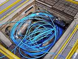
Fiber-optic cable in a Telstra pit
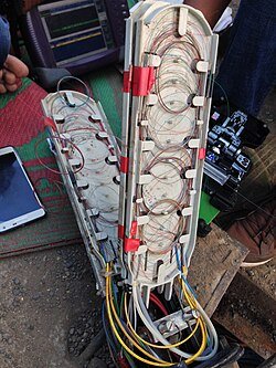
Investigating a fault in a fiber-optic cable distribution box. Individual strands of the fiber-optic cable are visible inside the distribution box.
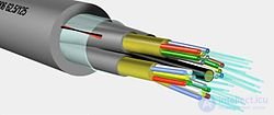
Cable for splitting an optical fiber
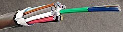
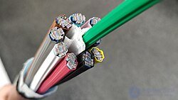
Use in more demanding environments requires a much more robust cable construction. In a loose-tube construction, the fiber is laid helically inside semi-rigid tubes, allowing the cable to stretch without stretching the fiber itself. This protects the fiber from tension during installation and from temperature fluctuations. Fiber in a loose tube can be dry-block or gel-filled. A dry block provides less protection for the fibers than gel, but costs significantly less. Instead of a loose tube, the fiber can be enclosed in a tough polymer sheath, commonly called tight-buffer construction . Tight-buffered cables are offered for a variety of applications, but the two most common are breakout and distribution cables. Breakout cables typically contain a ripcord, two non-conductive dielectric strength members (usually a fiberglass rod embedded in epoxy), an aramid yarn, and a 3 mm buffer tube with an additional layer of Kevlar surrounding each fiber. The ripcord is a parallel cord of strong thread placed under the cable's jacket(s) for stripping the sheath. [ 3 ] Distribution cables have a common Kevlar sheath, a ripcord, and a 900-micrometer buffer coating surrounding each fiber. These fiber bundles are usually bound with additional steel strength members, also helically twisted to provide tensile strength.
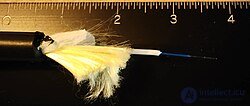
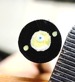
A critical task when laying cables outdoors is protecting the fiber from water damage. This is achieved by using solid barriers, such as copper tubes, as well as water-repellent gel or moisture-absorbing powder surrounding the fiber.
Finally, the cable can be armored to protect against environmental hazards, such as construction work or gnawing animals. Underwater cables have heavier armoring in the coastal zone to protect them from boat anchors, fishing gear, and even sharks , which can be attracted by the electric current carried to power amplifiers or repeaters in the cable.
Modern cables come with a wide variety of sheaths and armor designed for applications such as direct burial in trenches, dual use as power lines, installation in ducts, attachment to aerial telephone poles, underwater laying, and installation along paved streets.
The jacket material depends on the specific application. It determines mechanical strength, chemical resistance, UV resistance, and so on. Common jacket materials include LSZH , PVC , polyethylene , polyurethane , polybutylene terephthalate , and polyamide .
Two main types of materials are used to make optical fibers: glass and plastic. They have very different characteristics and are used in very different fields. Generally, plastic fiber is used for very short distances and consumer applications, while glass fiber is used for telecommunications over short/medium ( multimode ) and long ( single-mode ) distances. [ 4 ]
In hollow-core optical fibers, light propagates through air rather than through solid glass. In 2025, double nested antiresonant nodeless fiber (DNANF) achieved a record transmission loss of 0.091 dB/km at a wavelength of 1550 nm, lower than the best solid-silica fibers (≈0.14 dB/km). [ 5 ] [ 6 ] Field trials in China demonstrated an 800 Gbit/s hollow-core communication link over more than 20 km, with splice losses of only 0.05 dB and average cable loss of 0.6 dB/km. [ 7 ] Hollow-core fibers reduce latency, since light travels faster in air than in glass, and also suppress nonlinear effects and dispersion. [ 8 ] [ 9 ]
In September 2012, NTT Japan demonstrated a single fiber-optic cable capable of transmitting 1 petabit per second ( 10¹⁵ bit/s ) over a distance of 50 kilometers. [ 10 ]
Although larger cables are available, [ 11 ] the most common single-mode fiber cable with the highest strand count is an 864-strand cable made up of 36 ribbons, each containing 24 fiber strands. [ 12 ] These high-fiber-count cables are used in data centers , [ 11 ] as well as distribution cables in HFC and PON networks. [ 13 ] [ 14 ] [ 15 ]
In some cases only a small portion of the fibers in a cable is actually used. Companies may lease or sell unused fiber to other providers looking for service in or through a given area. Depending on specific local regulations, companies may build their networks with excess fiber in order to create a large network of unused fiber for sale, which reduces the overall need for trenching and obtaining municipal permits. Alternatively, they may deliberately underinvest to prevent their competitors from profiting from their investments.
Optical fibers are very strong, but their strength is drastically reduced by unavoidable microscopic surface defects inherent to the manufacturing process. The initial strength of the fiber, as well as its change over time, must be considered relative to the stresses acting on the fiber during transport, cable installation, and mounting under given environmental conditions. There are three main scenarios that can lead to reduced strength and failure due to defect growth: dynamic fatigue, static fatigue, and zero-stress aging.
Telcordia GR-20, « Generic Requirements for Optical Fiber and Optical Fiber Cable », contains reliability and quality criteria for protecting optical fiber under all operating conditions. [ 16 ] The criteria focus on outside plant (OSP) conditions. For inside plant, similar criteria are given in Telcordia GR-409, « Generic Requirements for Indoor Fiber Optic Cable» . [ 17 ]
Optical cables transmit data at the speed of light in glass. This is the speed of light in a vacuum divided by the refractive index of the glass used, typically around 180,000–200,000 km/s , resulting in a delay of 5.0–5.5 microseconds per kilometer. Thus, the round-trip delay over a distance of 1000 km is about 11 milliseconds. [ 18 ]
Signal loss in an optical fiber is measured in decibels (dB). A loss of 3 dB on a communication line means that the light intensity at the other end is only half the intensity of the light that entered the fiber. A loss of 6 dB means that only a quarter of the light passed through the fiber. Once too much light is lost, the signal becomes too weak to recover, the link becomes unreliable, and eventually stops functioning altogether. The exact point at which this happens depends on the transmitter power and receiver sensitivity.
Typical modern graded-index multimode fibers have an attenuation of 3 dB per kilometer (signal loss) at a wavelength of 850 nm and 1 dB/km at 1300 nm. Single-mode fiber loses 0.35 dB/km at 1310 nm and 0.25 dB/km at 1550 nm. High-quality single-mode fiber designed for long-distance transmission has losses of 0.19 dB/km at 1550 nm. [ 19 ] Plastic optical fiber (POF) loses much more: 1 dB/m at 650 nm. POF is a large-core fiber (about 1 mm) suitable only for short, low-speed networks, such as the TOSLINK optical audio system , or for use in automobiles. [ 20 ]
Each splice between cables adds approximately 0.6 dB of average loss, and each connection (connector) adds approximately 0.1 dB. [ 21 ] Many fiber-optic cable connections have a loss budget , which is the maximum permissible amount of loss. [ 22 ]
Commercial glass-fiber-based communication systems use invisible infrared light (750 nm and above), since it has lower attenuation in such materials than visible light. However, glass fiber also transmits visible light, which is convenient for simple fiber testing without the need for expensive equipment. Connections can be visually inspected and adjusted to minimize light leakage at the joint, which maximizes light transmission between the ends of the fibers being joined.
The diagrams «Understanding Wavelengths in Fiber Optics» [ 23 ] and «Optical Power Loss (Attenuation) in Fiber» [ 24 ] illustrate the relationship between visible light and the infrared frequencies used, and show water absorption bands between 850, 1300, and 1550 nm.
Fiber-optic cables are significantly more efficient than copper, meaning lower energy consumption compared to traditional copper cable infrastructure. [ 25 ] [ 26 ] This contributes to greater environmental sustainability both for the transmission itself and by reducing the need for cooling in data centers and network hubs. [ 27 ]
The infrared light used in telecommunications is invisible, so there is a potential safety hazard for technicians working with lasers . The eye's natural protection from sudden exposure to bright light — the blink reflex — is not triggered by infrared sources. [ 28 ] In some cases power levels are high enough to damage the eyes, especially when using lenses or microscopes to inspect fibers emitting invisible infrared light. Microscopes with optical protective filters are available to guard against this. Indirect viewing aids have recently come into use, which may include a camera mounted in a handheld device with an opening for the connected fiber and a USB output for connecting to a display device, such as a laptop. This makes inspecting a connector's end face for damage or contamination much safer.
Small glass fragments can also pose a problem if they get under the skin, so care must be taken to ensure that fragments produced when cleaving a fiber are properly collected and disposed of.
This list includes both standard and real-world technical cable types used in fiber-optic infrastructure, telecommunications, enterprise networks, and outdoor applications.
The jacket or protective sheath of patch cords is often color-coded to indicate the type of fiber used. The protective boot , which prevents the fiber from bending at the connection point, is also color-coded to indicate the connector type. Connectors with plastic housings (such as SC connectors ) usually have color-coded housings. Standard color designations for jackets (or protective sheaths) and protective boots (or connector housings) are shown below:
| Color | Meaning | |
|---|---|---|
| Orange | Multimode optical fiber | |
| Aqua | OM3 or OM4 10 G laser-optimized optical fiber, multimode , 50/125 μm. | |
| Erika violet [ 30 ] | multimode OM4 optical fiber (some manufacturers) [ 31 ] | |
| Lime green [ 32 ] | OM5 10 G + wideband multimode 50/125 μm optical fiber | |
| Gray | Legacy color coding for multimode optical fiber. | |
| Yellow | Single-mode optical fiber | |
| Blue | Sometimes used to denote polarization-maintaining optical fiber. | |
| Color | Meaning | Comment | |
|---|---|---|---|
| Blue | Physical Contact (PC), 0° | Mostly used for single-mode fibers; some manufacturers use it for polarization-maintaining optical fibers. | |
| Green | Angled Polish (APC), 8° | ||
| Black | Physical Contact (PC), 0° | ||
| Gray | Physical Contact (PC), 0° | Multimode fiber-optic connectors | |
| Beige | |||
| White | Physical Contact (PC), 0° | ||
| Red | High optical power. Sometimes used for connecting external pump lasers or Raman pump lasers. | ||
Note: It is also possible for a small part of the connector to have an additional color marking, such as the E-2000 connector latch or fiber-optic adapter frame . This additional color marking indicates the correct port for the patch cord if many patch cords are installed at a single point.
Individual fibers in a multi-fiber cable are often distinguished from one another by the color coding of the jackets or buffers on each fiber. The identification scheme used by Corning Cable Systems is based on the EIA/TIA-598 standard «Color Coding of Optical Fiber Cables», which defines identification schemes for fibers, buffered fibers, fiber units, and groups of fiber units in outdoor and indoor optical fiber cables. This standard allows fiber units to be identified using printed markings. This method can be used to identify fiber ribbons and fiber sub-units. The marking will contain the corresponding printed numerical position number or color for identification purposes. [ 33 ]
|
|
||||||||||||||||||||||||||||||||||||||||||||||||||||||||||||||||||||||||||||||||
The color coding above resembles the colors of polyethylene copper cables used in standard telephone wiring.
A different color code is used in the United Kingdom. Each 12-fiber bundle or element in a Cable Optical Fibre 200/201 cable is colored as follows:
| Position | jacket color | Position | jacket color |
|---|---|---|---|
| 1 |  blue |
7 |  brown |
| 2 |  orange |
8 |  violet |
| 3 |  green |
9 |  black |
| 4 |  red |
10 |  white |
| 5 |  gray |
11 |  rose |
| 6 |  yellow |
12 |  turquoise |
Each element sits in a tube inside the cable (not a tube made of synthetic fiber). Cable elements begin with a red tube and are counted around the circumference of the cable up to a green tube. Active elements are in white tubes, and yellow filler rods or plugs are laid into the cable to fill it out, depending on the number of fibers and elements – there can be up to 276 fibers or 23 elements for an outdoor cable and 144 fibers or 12 elements for an indoor one. The cable has a central strength member, usually made of fiberglass or plastic. Outdoor cables also have a copper conductor.
Hybrid optical and electrical cables are used in outdoor wireless Fiber To The Antenna (FTTA) communication systems. In these cables, the optical fibers carry information, while the electrical conductors are used to carry power. Such cables can be installed in various environments to service antennas mounted on poles, towers, and other structures.
According to Telcordia GR-3173 , Generic Requirements for Hybrid Optical and Electrical Cables for use in Outdoor Wireless FTTA (Fiber To The Antenna) Applications, these hybrid cables have optical fibers, twisted pairs/quads, coaxial cables, or current-carrying electrical conductors under a common outer jacket. The power conductors used in these hybrid cables are designed to directly power the antenna or to power tower-mounted electronics serving only the antenna. They have a nominal voltage, typically less than 60 V DC or 108/120 V AC. [ 34 ] Depending on the application and the applicable National Electrical Code (NEC), other voltages may be present.
These types of hybrid cables can also be useful in other environments, such as at Distributed Antenna System (DAS) sites, where they will serve indoor, outdoor, and rooftop antennas. In such environments, factors such as fire resistance, compliance with Nationally Recognized Testing Laboratory (NRTL) standards, placement in vertical shafts, and other performance-related issues must be fully taken into account.
Since the voltage and power levels used in these hybrid cables vary, under electrical safety codes a hybrid cable is treated as a power cable, which must comply with regulations governing the required clearances, distances, etc.
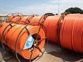
An inner duct made of high-density polyethylene (HDPE)
Inner ducts are installed in existing underground conduit systems to provide clean, continuous, low-friction paths for laying optical cables with relatively low pulling-tension limits. They make it possible to divide conventional conduits, originally designed for single, large-diameter metallic-conductor cables, into several channels for smaller-diameter optical cables.
Inner ducts are usually semi-flexible, small-diameter conduits. According to Telcordia GR-356, there are three main types of inner ducts: smooth-wall, corrugated, and ribbed. [ 35 ] These different designs are based on the profile of the inner duct's inner and outer diameters. The need for a particular characteristic or combination of characteristics, such as tensile strength, flexibility, or the lowest coefficient of friction, determines the required type of inner duct.
In addition to the basic profiles or contours (smooth-wall, corrugated, or ribbed), inner duct is also available in an increasing variety of multi-channel designs. A multi-channel inner duct can be either a composite unit made up of four or six separate inner ducts joined mechanically, or a single extruded product with multiple channels for laying several cables. In either case, a multi-channel inner duct can be coiled and pulled into an existing conduit in the same way as a conventional inner duct.
Inner ducts are mainly installed in underground conduits that provide connecting paths between manholes. In addition to being installed in conduits, inner duct can be buried directly in the ground or installed overhead by attaching it to a steel messenger wire.
As stated in GR-356, cable is usually installed in an inner duct in one of three ways. It can be


Comments