
Lecture
A fiber-optic communication line (FOCL) - is a line connecting two electrical circuits by transferring information using a light signal inside an optical fiber (a thin glass or plastic strand). The operating principle of an optical fiber is based on the effect of total internal reflection. The input signal modulates a light source, and photodetectors are used to convert the light back into an electrical signal. Thus a FOCL includes the following main components:
1) transmitter;
2) cable based on optical fiber;
3) receiver;
4) connectors.
For more complex lines and communication networks, additional elements are used, such as splitters, multiplexers and distribution devices.
LEDs and semiconductor lasers are used as transmitters.
Radiation with the following wavelengths is mainly used for transmitting information: 1550 nm, 1300 nm, 850 nm, in order to ensure minimal attenuation in optical fibers.
LEDs can emit light with a wavelength of 850 nm and 1300 nm. Emitters with a wavelength of 850 nm are significantly cheaper than emitters with a wavelength of 1300 nm. At the same time, the bandwidth of the cable for 850 nm waves is narrower (200 MHz/km instead of 500 MHz/km). For the operating principle, characteristics and design of LEDs, see Lecture No. 7.
Laser emitters operate at wavelengths of 1300 nm and 1500 nm. The speed of modern lasers allows the light flux to be modulated at frequencies of 10 GHz and above. Laser emitters create a coherent light flux, due to which losses in optical fibers become lower than when using an incoherent flux from an LED. For the operating principle, characteristics and design of lasers, see the section on semiconductor lasers
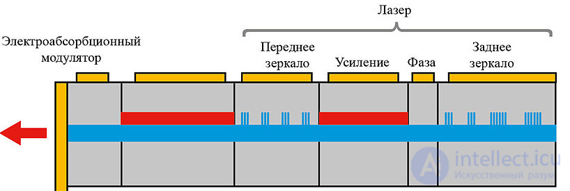
Diagram of an integrated single-block optical transmitter based on a tunable laser with an external modulator and amplifier
In optical transmitters with external modulation, continuous optical radiation is modulated by an external modulator controlled by an information electrical signal. The radiation sources in such transmitters are typically narrow-band single-mode continuous-wave semiconductor lasers: DFB lasers or DBR lasers.
This ensures the formation of an optical signal with a minimal spectral width. In addition, in transmitters with external modulation, along with amplitude (power) modulation, modulation of other parameters of the light waves is used to encode information: phase, frequency and polarization, as well as combinations thereof. Transmitters with external modulation are used in long-haul communication systems, where the requirements for optical signal quality are maximal. The most widely used types of modulators in communication systems are Mach-Zehnder modulators and electro-absorption modulators.
In communication systems with dense wavelength-division multiplexing (DWDM), transmitters with a tunable emission wavelength are used. To increase the power of the optical signal, optical amplifiers may be included in the optical transmitter.
Transmitters for digital fiber-optic communication systems are often manufactured in a single housing together with receivers, forming transceiver optical modules, or transponders.
Design.
An optical fiber consists of a central light conductor (the core) and a surrounding optical cladding with a lower refractive index. As light rays propagate through the core, they do not go beyond its boundaries, undergoing reflection at the core-cladding interface. Light striking the boundary at an angle smaller than the critical angle will penetrate the optical cladding and attenuate as it propagates through it, since the optical cladding is not designed to carry light. Fibers also have an additional protective coating that protects the core and optical cladding from impacts. The fibers themselves have an extremely small diameter.
Fig.1 shows the diagram of light propagation along a fiber. Light is introduced into the fiber at an angle greater than the critical angle to the "core/optical cladding" boundary, and undergoes total internal reflection at this boundary. Since the angles of incidence and reflection are equal, the light will continue to be reflected from the boundary. Thus, the light ray will travel in a zigzag pattern along the fiber.
Characteristics of fiber-optic cables.
- Dispersion– is the dependence of the phase velocity of a wave propagating in an optical cable on frequency.
- Number of modes in the fiber. From specialized branches of physics it is known that the parameters of an optical fiber determine the number of electromagnetic waves (modes) that can propagate in it. For each fiber there exists a critical value (KR), such that all waves with a value <KR will not propagate. By changing KR, it is possible to achieve propagation of the required number of waves (modes) in the fiber. For propagation of radiation at a single wavelength (mode), it is necessary that all wavelengths emitted by the source, except one, have a value >KR.
- Bandwidth – often specified instead of dispersion for multimode fibers, expressed in megahertz per kilometer (MHz/km). A bandwidth of 400 MHz/km means the ability to transmit a signal in a 400 MHz band over a distance of 1 km, i.e. the product of the maximum signal frequency and the transmission length can be less than or equal to 400. In other words, a lower-frequency signal can be transmitted over a longer distance, or a higher-frequency signal over a shorter distance, as shown in Fig.1.
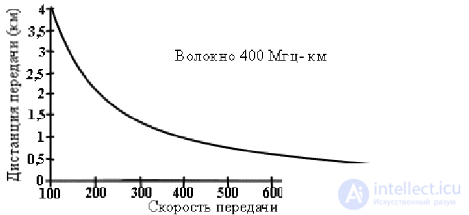
Fig.1
Expressing bandwidth in terms of single-mode dispersion is complex; an approximate estimate can be obtained based on the following equation:
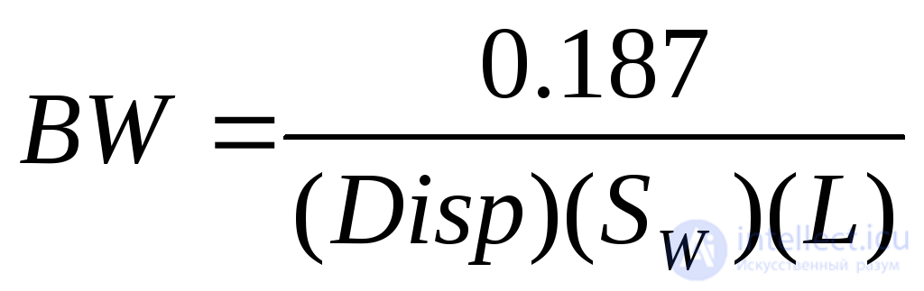 , (2)
, (2)
where: Disp - dispersion at the operating wavelength, in seconds per nanometer per kilometer;
SW - source spectral width in nm; L - fiber length in km.
-
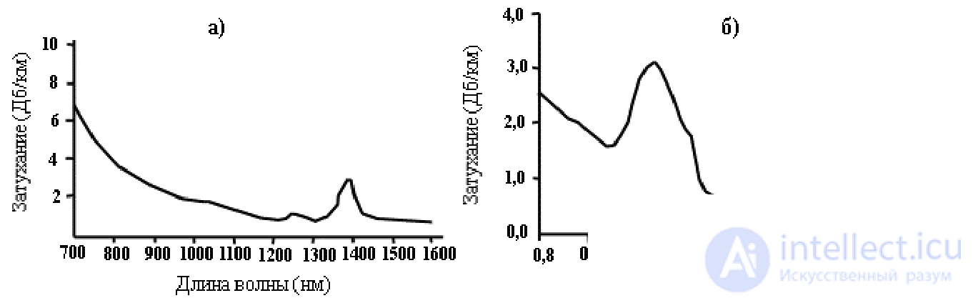 Fig.2
Fig.2
Attenuation – is the loss of optical energy as light travels along a fiber, measured in decibels per kilometer. Attenuation depends on the wavelength of the light. There are transparency windows in which light propagates along a fiber with low attenuation. Consequently, when a light source operates in these ranges, transmission losses in the fiber will be minimal. Fig.2a shows a typical attenuation curve for a low-loss multimode fiber. Fig.2b shows the same curve for a single-mode fiber. The most important feature of attenuation in an optical fiber is its independence from the modulation frequency within the bandwidth.
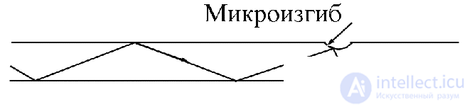
Fig.3
Attenuation in the fiber is determined by three effects: scattering, absorption, and the presence of microbends. Fig.3 shows that variations at the boundary can cause reflection of high-order modes at angles that do not allow further reflection.
- Numerical aperture (NA) - determines the fiber's ability to collect light rays. NA depends on the properties of the fiber materials and is determined by the refractive indices of the core and optical cladding: 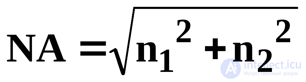 . NA of the fiber indicates how light is coupled into the fiber and propagates through it. A fiber with a large NA value (i.e. implying a greater number of possible light paths) accepts light well, while a fiber with a small NA value (fibers with a wide bandwidth) can only accept a narrowly-directed light beam.
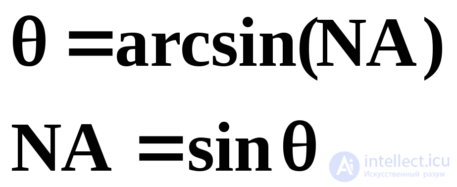
It is also possible to determine the magnitude of the angles at which light propagates along the fiber. These angles form a cone called the acceptance cone, whose angular spread determines the maximum angle for coupling light into the fiber.
 (3)
(3)
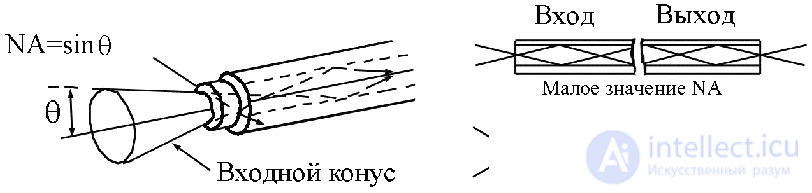 Fig.4
Fig.4
where - is half the acceptance angle (Fig.4).
The source and receiver also have their own apertures:
NAsrc of the source determines the angular aperture of the input light.
NAdet of the detector determines the working range of angles for the receiver.
It is very important to satisfy the condition: NAsrc = NAdet. A mismatch in NA leads to additional losses when transferring light from a device with a smaller NA value to a device with a larger one.
- Fiber strength- characterizes the fiber's ability to withstand tension, breakage and bending without damage. The main cause of fiber fragility is the presence of microcracks on the surface and defects within the fiber. Surface defects can increase under the tensile load that arises during cable laying. Temperature changes, mechanical and chemical effects, and ordinary aging also lead to the appearance of defects. Glass fibers can be bent into a circle of small diameter. It must be remembered that the minimum bend radius is five cable diameters in the absence of tensile stress, and 10 cable diameters when tensile stress is present.
- Radiation resistance – determines the equipment's ability to withstand nuclear effects. Unlike conductors, fibers do not accumulate static charges under the influence of radiation. Fibers also are not damaged instantly after their cable jacket melts under the thermal effect of a radiation source.
Fibers resist an increase in attenuation under conditions of continuous high-intensity radioactive exposure. The increase in attenuation depends on the accumulated dose and the intensity of the exposure.
Depending on the type of fiber material, fibers are divided into:
1) glass fibers with a glass core and a glass optical cladding;
2) glass fibers with a glass core and a plastic optical cladding (PCS);
3) plastic fibers, having a plastic core and a plastic optical cladding.
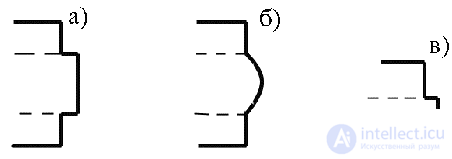 Fig.5
Fig.5
Depending on the refractive index profile distribution, a distinction is made between step-index and graded-index fibers (Fig.5).
By number of propagating modes, the following are distinguished:
-
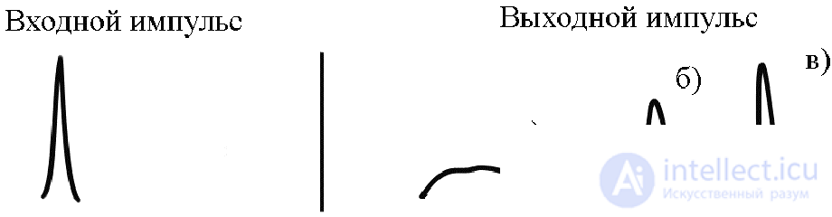 Fig.6
Fig.6
Single-mode fiber(see Fig.5.c, 6.c, 7.c) has an extremely small diameter - from 5 to 10 microns, and a step-index refractive index profile. The light ray in such a cable has high intensity. Therefore single-mode cables are suitable for transmission over long distances.
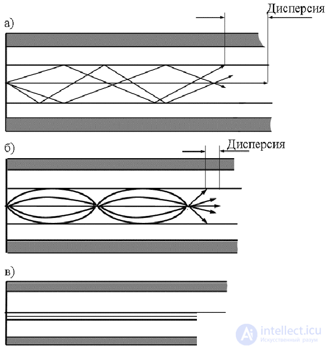
Fig.7
Single-mode fibers can be manufactured to work with a shorter cutoff wavelength. These fibers are used in specialized television, computer and control systems. However, the higher attenuation value, up to 10 dB/km at 633 nm, limits the fiber's use over long distances.
- Multimode fiber has a core diameter from 100 to 970 microns and a step-index or graded-index refractive index profile (Fig 5.a.b, 6.a.b, 7.a.b). This type of fiber is the most widespread, although it does not provide the maximum bandwidth and minimum losses. When a fiber operates in multimode, undesirable phenomena occur related to equilibrium mode distribution (EMD). EMD – is a steady state in a multimode optical fiber in which energy is distributed among modes independently of wavelength. In an ideal fiber, energy that initially exists in a particular mode is retained in that mode. But in reality, energy transfers between modes, which is related to fiber bends, variations in core diameter and refractive index, or fiber inhomogeneities. As it travels, energy will transfer from one mode to another until EMD is reached. After this, no further redistribution of energy between modes occurs under normal conditions. In the absence of EMD, a fiber is called overfilled or underfilled. In an overfilled fiber, inefficient modes participate in carrying optical energy. In an underfilled fiber, light propagates only in low-order modes. As it travels, part of the energy contained in these modes will transfer into high-order modes, and EMD will be reached. The distance at which EMD is reached depends on the type of fiber.
Fiber-Optic Cable Design
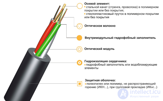
Fig.8 shows the main components of a simple optical cable with a single fiber. Cable designs can vary quite widely, but the following components are common:
-
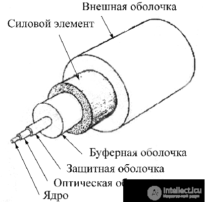 Fig.8
Fig.8
optical fiber.
- buffer coating(there are two types of cable buffers: loose-tube and tight-buffered), provides better protection against mechanical stress, but does not protect the fiber from temperature changes as well. Since the plastic expands and contracts to a different degree compared to the fiber, contraction caused by a drop in temperature can lead to the formation of microbends.
- strength member– increases the mechanical strength of the cable.
- outer jacket– provides protection against mechanical friction, oil, ozone, acids, alkalis, solvents, etc.
According to operating conditions, fiber-optic cables can be divided into indoor and outdoor types.
Comparative characteristics of cables are given in the table.
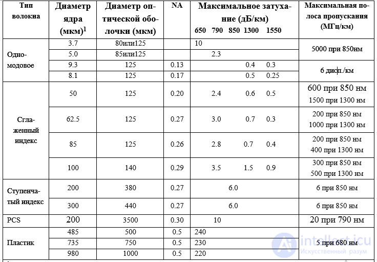
1Mode field diameter is given for single-mode fiber; the actual diameter is smaller.
2Dispersion per nanometer of source spectral width
3Plastic fibers are usually used over distances up to 100 m, with a transmission rate of 50 Mbit/sec.
Fiber-optic cables have recently found increasing use because they provide high data transmission speed and broad bandwidth. In many parameters they surpass conventional cables; in addition they are corrosion-resistant and prevent unauthorized access to the data transmitted over them.
Photodetectors are used to convert optical signals into electrical signals. In fiber-optic communication, photodiodes (p-i-n and APD) are used as photodetectors.
The spectral sensitivity range depends on the material from which the photodiode is made. In the visible and near-infrared range (0.75...1.1 microns), photodiodes made on the basis of silicon have the best sensitivity. For operation in the range λ = 1.7 microns, photodiodes based on Ge (Germanium) and so-called quaternary InGaAs/InP structures have been developed.
If a signal consisting of several frequencies propagates in the optical cable, then wavelength-selective photodetectors are used at the receiving end to extract the required signal.
Photodiodes used in FOCLs must have sufficient quantum efficiency (η) and speed; for other parameters see the lecture "Photodetectors".
Standard MIC- and ST-type connectors are used in fiber-optic cables.
A serious drawback of FOCLs is the difficulty of connecting fibers to connectors. Attaching an optical fiber to a connector requires high-precision cleaving of the fiber in a plane strictly perpendicular to the fiber axis, as well as making the connection through a complex bonding operation. Making poor-quality connections sharply narrows the bandwidth of fiber-optic cables and lines.
To perform a quality fusion splice of optical fibers, it is necessary to use a professional fiber-optic fusion splicer and a good precision optical fiber cleaver. Among fiber-optic fusion splicing equipment (also called optical fusion splicers), products from the Japanese company Fujikura are especially popular. The fusion splicers produced by this company are distinguished by legendary reliability, ease of use and relatively low price. Fujikura splicers have held the top position among comparable devices for many years and allow splicing any type of modern fiber on all types of networks: backbone, metro, regional, FTTx, PON, structured cabling systems (SCS), etc.
In this brief overview of fusion splicing technology, we will try to describe the main stages of splicing optical fibers.
Precision automatic equipment and tools are used for splicing optical fibers.
The optical fiber splicing process begins with the mandatory procedure of preparing the optical cable, removing the protective coatings from the fiber and removing the varnish layer of urethane-acrylate compounds. This procedure is performed using a special fiber optic tool called a stripper. Such a tool is capable of removing a coating from the fiber with a thickness of a hundred microns. If the varnish layer is not removed, it will ignite during arc fusion splicing. Moreover, such an important part of the splicer as the mirror will become covered with soot and may fail permanently.
Therefore, the fiber is stripped, all coatings are removed, leaving only the 125 micron outer cladding. The length of bare fiber for splicing must not be less than 60 cm. Consequently, it is necessary to clean all the optical strands of the fiber cable from residual hydrophobic gel using a special cleaning compound, D-Gel, or isopropyl alcohol, if necessary.
Leaving a small section of bare fiber, several centimeters long, we proceed to the next stage of splicing – cleaving the fiber.
The fiber cleaver performs a very important function - preparing the fibers for splicing. An important feature of cleavers is the simplicity of performing the fiber cleaving operation. In second place are the compact size of the fiber cleaver and its functionality, which allows quickly getting rid of sharp fiber fragments.
Thus, the automatic fiber cleaver Fiber Fox Mini 50GB produces a high-precision fiber cleave. The Mini 50GB cleaver is equipped in its design with a universal fiber clamp, which makes it possible to work with fiber-optic cable in a coating from 250 microns to 3 mm, of buffered, modular or flat construction (Flat OF Cable).
The fiber fragment collection tray of the Fiber Fox Mini 50GB cleaver helps ensure all safety requirements when working with optical fibers and quickly provides the required ergonomics at the operator's workstation.
The compact and lightweight Fiber Fox Mini 50GB cleaver makes the work on it not tiring, even with large volumes of fibers to be spliced, and any splicing specialist would envy the simplicity of working on this cleaver.
Now let's discuss the fiber cleaving procedure itself. Fiber cleaving is performed in two stages: in the first, the fiber is scored with the cleaver's blade, and in the second stage the fiber is broken by a striking mechanism. The cleaver's blade is round in shape and is rated for 10,000 - 50,000 cleaves with the quality declared by the manufacturer (the Fiber Fox Mini 50GB cleaver has a guaranteed cleave count exceeding 50,000 with a cleave angle not exceeding 90+/-0.5 degrees). This value is achieved through a rotating mechanism of the circular blade, which allows automatically changing its position and the height of the cutting edge.
In addition to the above, the Fiber Fox Mini 50GB cleaver has protection against impacts and drops from a height of up to 1 m. The protective plastic carrying case (yellow) of the Fiber Fox Mini 6S and 4S fusion splicers can be used as a work table when performing a complete splicing cycle in field conditions, which is a very convenient feature.
But the main thing – is the compactness and weight of Fiber Fox equipment! For example, the Fiber Fox Mini 50G cleaver weighs only 221 g, and the Fiber Fox Mini 50GB - 248 g.
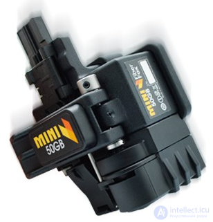
Fig.2 Fiber Fox Mini 50GB cleaver with a container for cleaved fiber fragments
Fusion splicing equipment uses splicing electrodes, and optical cleavers use specialized circular blades, which have a limited service life. All of these consumables are subject to replacement once their rated life is used up (fig. 3, fig. 4)
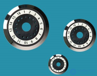
Fig.3 The circular blade for the Fiber Fox Mini 50GB cleaver can be ordered once the 50,000-cleave life is used up
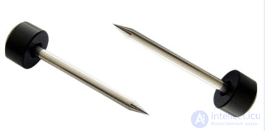
Fig.4 Splicing electrodes reliably serve for 3000 splices
The South Korean-made Fiber Fox Mini 4S and Mini 6S splicers belong to the same class of automatic fiber fusion splicers, which received the conventional name Active V-groove Alignment (named after the method of active fiber alignment by cladding/core).
Of course, there is also a simpler alignment method, known as Passive V-groove Alignment. This is a method of passive alignment of fibers by cladding. Fibers placed in special V-shaped grooves self-center as they are rotated and brought together. The entire alignment process takes place on the splicer's work table (fig. 6).
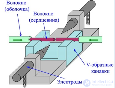
Fig.6 Passive fiber alignment in V-shaped grooves
The splicing process takes place in stages (fig. 7).
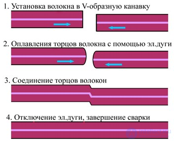
Fig. 7. Step-by-step splicing process using the passive fiber alignment method in V-shaped grooves
Without doubt, the precision of this fiber alignment method is low, and the attenuation of the splice will be quite high. Therefore, this quality of splicing would probably only satisfy owners of LAN networks. If splicing needs to be performed on the backbone segment of telecom operators, or on XPON or FTTX networks, then it is better to choose a fusion splicer with an active fiber alignment method for this purpose.
The Fiber Fox Mini 4S has 4 motors for aligning the optical fiber by cladding: two on carriages for feeding the fiber forward-backward along the Z axis, and two more motors on the grooves for preliminary alignment of the fibers in the X and Y planes.
The FiberFox Mini 4S – is a fully automatic fusion splicer designed for splicing fiber-optic cables of various types on FTTX and XPON networks. The Fiber Fox Mini 4S allows achieving record-low splice losses, less than 0.03 dB on single-mode fiber of the G.652 specification (fig. 8). And all this at an ultra-low weight of the Fiber Fox Mini 4S of only 1.35 kg without battery!
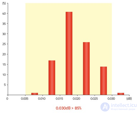
Fig. 8 Histogram of splice attenuation distribution for the Mini 4S. An attenuation frequency of 0.03 dB for single-mode fiber accounts for more than 85% of cases.
The Mini 4S has a fiber alignment-by-cladding system (Clad Alignment DCA) with automatic arc calibration and 4 work-table drive motors. Thanks to a patented work-table alignment algorithm using 4 motors, the Fiber Fox Mini 4S allows splicing optical fibers in a record 7 seconds. The control keys of the Fiber Fox Mini 4S are located on the display unit, which made it possible to significantly reduce the overall dimensions of the device. Thus, the overall dimensions of the Mini 4S do not exceed 13 cm in length, height and width. The automatic arc calibration capability of the Fiber Fox Mini 4S allows maintaining the device in optimal condition.
The flagship of the Fiber Fox company - the automatic Mini 6S fusion splicer, works using the core alignment method for optical fibers and has an automatic fiber type detection function. This fiber fusion splicer is designed for work on the backbone networks of telecom operators, since it has the highest alignment precision and minimal splice attenuation.
The Fiber Fox Mini 6S weighs only 1.39 kg without the battery pack and is capable of splicing optical fibers of the most common types, as well as fibers with non-zero and shifted dispersion and with a reduced bend radius, in accordance with ITU-T recommendation G.657. The splice attenuation on single-mode fiber for the device does not exceed 0.019 dB for 80% of splices (fig. 9).
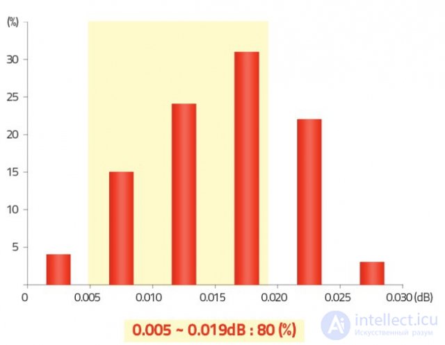
Fig. 9 Histogram of splice attenuation distribution for the Mini 6S. An attenuation frequency of 0.005-0.019 dB for single-mode fiber accounts for more than 80% of cases.
Thanks to the improved DWACAS (Digital Wavelength Automatic Core Alignment System) algorithm for aligning the work table using 6 motors and aligning fibers by core, patented by Fiber Fox, the Mini 6S fusion splicer allows splicing optical fibers in a record-short 7 seconds. The control keys of the Fiber Fox Mini 6S fusion splicer, like all devices in this product line, are located on the display unit, which made it possible to significantly reduce the overall dimensions. The device's dimensions are 122 x 124 x 131 mm. The Mini 6S has an automatic arc calibration capability, which allows maintaining the device in optimal condition.
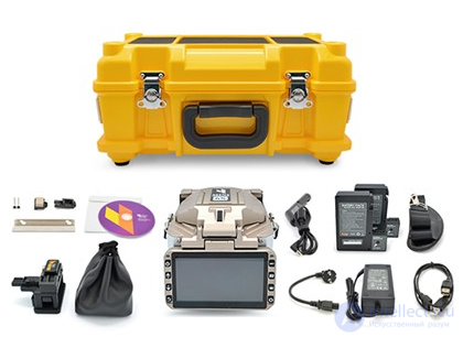
Fig.10. Fiber Fox Mini 6S in full configuration.
Both the Fiber Fox Mini 4S and Mini 6S fusion splicers come equipped with two battery packs. They can be charged not only while the device is idle, as was the case with most devices from well-known manufacturers. Now you can simply put down the fusion splicer with a charger connected to it, and after some time it will be fully charged. On a set of two batteries, the Fiber Fox Mini 4S and Mini 6S can perform a full 400 splicing cycles with subsequent heat shrinking, which significantly exceeds the daily splicing norms for an operator. If it is necessary to splice fibers several hundred times a day, the splicer kit includes a power supply and an adapter for connecting to a car cigarette lighter, which can be used to work practically without limit from the vehicle's onboard electrical system.
Another feature of the Fiber Fox Mini 4S and Mini 6S fusion splicers will surprise admirers of the reliability of South Korean brand equipment. Both devices withstand up to 3 drops from a height of about 1 meter. Moreover, all Fiber Fox splicing equipment is capable of operating in pouring rain with the windscreen cover closed, and in a dust storm with wind speeds of up to 15 m/sec.
Consequently, choosing a fiber splicer will require considering all the above parameters. And do not forget that sometimes high functionality indicators and ultra-low splice attenuation are not mandatory requirements for most fiber splicing work performed on FOCLs and in optical networks.
By the way, the functionality of the Fiber Fox Mini 4S and Mini 6S devices does not end there.
Quite often one hears fiber splicing specialists complain: they spliced it, but there's nothing to terminate the fiber with. And that's often how it turns out. After all, the complex of work on splicing FOCLs quite often also includes installing optical connectors on the fibers. So how can these seemingly different tasks be combined into one? And once again optical technologies from Fiber Fox come to the rescue.
The Fiber Fox Mini 4S and Mini 6S optical splicing equipment allows performing the installation of connectors on optical fibers using the fusion splicer itself directly. Such optical connectors, whose installation can be performed on splicing equipment, are called SOC (Splice-On Connector). Fiber Fox's portfolio includes SOC optical connectors in the most common form factors, FC and SC (fig. 11).
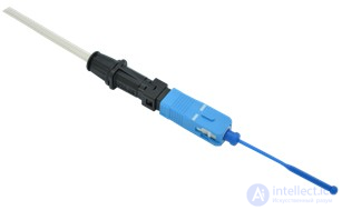
Fig. 11. SOC optical connector, SC form factor, for single-mode fiber with UPC polish.
The ability to terminate fiber with SOC (Splice-On Connector) connectors of SC and FC form factors on the MINI 6S (4S) devices has made the operator's work as fast and convenient as possible.
Specialists working on FOCL splicing on XPON and FTTX networks will readily confirm that here the most common fiber connector is the SC. And on the networks of telecom operators and providers the most popular fiber connector is the FC. And once again, right on target!
Indeed, very convenient! And most importantly, there's no need to carry additional heavy equipment for fiber termination, which often contains chemical reagents or energy-intensive heating equipment, which sometimes has nowhere to be plugged in.
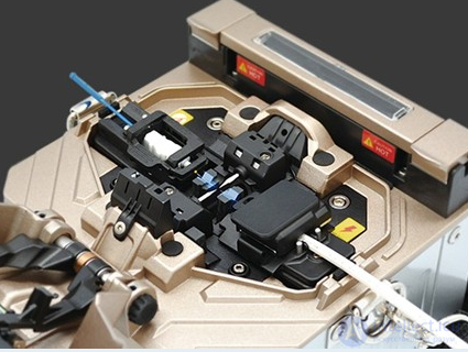
Fig.12. Installing a SOC connector on the Fiber Fox Mini 6S device
Now let's return to the splicing process. After all, we haven't finished it.
After placing the fibers in the holders on the splicer's work table, we simply watch as the device automatically performs the fiber alignment, and then splices them using an electric arc discharge. All Fiber Fox devices have a fast splicing time from 7 sec (Quick mode) and heat shrinking from 18 sec. These are the best figures in this segment. That's it, the fibers are spliced!
All that's left is a small matter – remove the fibers from the holders and perform the heat-shrinking operation.
Polyethylene terephthalate (PET) heat-shrink splice protection sleeves, made of heat-shrinkable PET, are used for heat shrinking. The most popular splice protection sleeves are 40 mm and 60 mm long. (fig. 13).
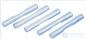
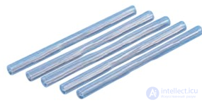
Fig.13. Heat-shrink splice protection sleeves, 40 mm (left) and 60 mm (right), for protecting splices.
When heated in a special oven, the heat-shrink splice protection sleeve shrinks, sealing the splice located inside. Inside the sleeve there is a metal rod installed, which protects the splice from mechanical loads and bending.
Heating is carried out in a specialized heater (oven) with a Teflon coating, so that the PET sleeve "does not burn".
We remove the just-spliced fiber from the device's work table. But, almost immediately, when opening the windscreen cover, we hear the mechanical splice strength-testing system activate. The fibers are subjected to a dosed tension to test the strength of the completed splice.
We place the splice into the heat-shrink oven. We close the oven cover, lightly pressing on the ends of the fiber near the boundaries of the splice. The heat-shrinking operation begins.
All Fiber Fox Mini 4S and Mini 6S devices use a high-performance oven, allowing splice protection sleeves to be installed in a minimal 18 seconds!
At the end of the heat-shrinking process, we hear a characteristic signal. This is how our Fiber Fox fusion splicer indicates that heat shrinking is complete. After ventilating the oven, the device thoughtfully waits for the start of a new splicing-with-heat-shrinking cycle.

Comments