
Lecture
An overview of equipment from manufacturers producing DWDM equipment. DWDM (Dense Wavelength Division Multiplexing) technology provides the highest throughput when using a single optical pair. High throughput is achieved through the use of wavelength-division multiplexing technology, whereby several independent streams are transmitted over one optical pair, each on its own wavelength. Equipment available today allows the use of up to 160 optical channels, with the possibility of expansion to 300 channels in the future. In each such channel, an information stream is transparently transmitted at speeds from 100 Mbit/s to 40 Gbit/s. The introduction of Dense Wavelength Division Multiplexing (DWDM) technology makes it possible to increase the efficiency of traffic transmission in the optical channels of metropolitan networks. The most attractive feature of DWDM technology, both from a technical and an economic standpoint, is its ability to support virtually unlimited traffic transmission capacity. It not only protects investments made in existing fiber-optic channels, but also increases their capacity by at least 32 times. As demand grows, you can expand your network's capacity through simple equipment upgrades or by increasing the number of wavelengths used, without resorting to costly reconstruction. When expanding capacity, you only pay for new equipment. As for the cable network, it remains unchanged.
The main network elements of a DWDM network are:
Besides bandwidth, DWDM technology offers a number of other advantages:
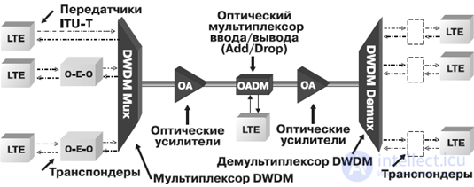
Fig. 3.27 . Block diagram of a backbone DWDM system
The reliable operation of backbone networks underpins the functioning of international and long-distance telephone communication, the Internet, and the corporate networks of many large companies.
Of course, within the scope of this thesis it is impossible to cover all manufacturers producing SDH and DWDM equipment. Therefore, we will only be able to review a portion of the equipment available on the Russian market.
The tables show the main technical characteristics for several groups of DWDM equipment.
Alcatel. Alcatel offers the OPTINEX family of products for telecom operators to the market. In accordance with the adopted concept, on backbone networks preference is given to DWDM with support for dynamic reconfiguration of optical paths, as well as to SDH technologies. A number of DWDM products are optimized for metropolitan-scale networks.
Alcatel 1680 SM devices are designed for building high-speed backbone networks, operate exclusively at the STM-64 level, and serve as a kind of access gateway to the optical layer of the network. The OPTINEX family includes three DWDM equipment models. The Alcatel 1686 WM is a system supporting 16 or 32 optical channels. Each of them can operate at speeds from 100 Mbit/s to 10 Gbit/s. For high-performance backbone networks, the Alcatel 1640 WM model is suitable, providing multiplexing of up to 80 optical channels.
ZTE. This Chinese company offers a whole range of DWDM equipment on the Russian market. The ZXWM-32 device is a DWDM multiplexing system and can achieve a total transmission rate of up to 400 Gbit/s.
Lucent Technologies. Lucent Technologies produces a whole range of synchronous transmission and optical multiplexing equipment, united under the common name WaveStar. The junior SDH model line consists of three STM-1 multiplexer models.
Table 3.12 DWDM systems.
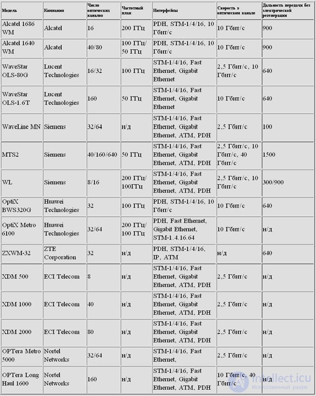
They can be used to build backbone networks and organize access. The WaveStar AM-1 Plus is designed for the latter task. Depending on the configuration, it can also work with an STM-4 stream. This small device has a desktop design, quite similar in size and shape to modems from five years ago. One additional card can be inserted into this multiplexer, expanding its capabilities for connecting equipment with various interfaces. For STM-1, STM-4, STM-16 hierarchy networks, three models with the ADM index are offered. The most powerful device in this group is the intelligent WaveStar ADM 16/1 multiplexer. It allows cross-connection of E1 streams and access to them directly at the STM-16 level. If a throughput of 2.5 Gbit/s is not sufficient, a high-performance WaveStar TDM 10G multiplexer, operating at the STM-64 level, can be installed. However, the existing lower-level multiplexers will have to be retained, since the lowest-speed tributary interface is STM-1. Lucent Technologies' DWDM equipment includes the WaveStar OLS family and the Metropolis MSX multiservice platform. The simplest DWDM system is the WaveStar OLS 80G, supporting up to 16 optical channels in the 1550 nm range. This system, in the WaveStar OLS 400G modification, expands to 80 optical channels, and in the WaveStar OLS 1.6T modification, to 160 channels. Each of the channels formed can transmit information at 10 Gbit/s (STM-64), which corresponds to a throughput of 1.6 Tbit/s over a single optical fiber.
Nortel Networks. This company's DWDM equipment is one of the most popular in the world. Among its DWDM equipment, it is worth noting the OPTera Long Haul 1600, which provides high throughput, and the OPTera Metro 5000, designed for building city-scale high-speed networks.
Siemens. As with other companies, Siemens' arsenal includes a whole family of multiplexers called TransXpress. In the field of DWDM, Siemens probably offers the widest range of equipment for backbone, regional, and metropolitan networks. For example, the MTS2 model, designed for high-capacity, high-throughput backbone networks, can transmit up to 640 channels at 2.5 Gbit/s each over a distance of more than 1000 km. For less ambitious tasks, the WL class of equipment, supporting only 8 or 16 optical channels, can be used.
Huawei Technologies. Recently, Huawei has become noticeably more active on the Russian market. It operates in many areas of telecommunications, including the creation of equipment for backbone networks. For this direction, the OptiX family has been developed, which includes SDH multiplexers at STM-1/4/16/64 levels, DWDM equipment for 16/32 channels, and the MSTP multiservice transport platform. The latter combines the advantages of SDH and DWDM. Currently, only three products implementing MSTP have been created. All of them are designed for building city-scale networks and allow the integration of SDH, ATM, and IP traffic.
ECI Telecom. In January 2001, the division responsible for the corresponding equipment was transformed into Lightscape Networks, part of the ECI Telecom group of companies. This manufacturer is fairly well known on the Russian market, where it offers a range of SDH multiplexers operating at STM-1/4/16 levels, as well as the mic-roSDM-1 single-board multiplexer at the STM-1 level. The XDM series of universal multiplexers integrates on a single platform the functions of DWDM multiplexing, cross-connection, an IP router, an ATM switch, and SDH multiplexers. Currently, three models are offered to customers. The junior model, XDM 500, is an access gateway from digital networks to DWDM networks. The XDM 1000 is a multiservice switch for optical metropolitan networks. The senior model, XDM 2000, is positioned by the company as a multifunctional intelligent switch. All devices are capable of handling streams from E1 to STM-64.
Dense Wavelength Division Multiplexing (DWDM) is a modern technology for transmitting a large number of optical channels over a single fiber, which underlies the new generation of network technologies. The telecommunications industry is currently undergoing unprecedented changes associated with the transition from voice-oriented systems to data transmission systems, a consequence of the rapid development of Internet technologies and various network applications. With the large-scale deployment of data transmission networks, the very architecture of networks is being modified. This is precisely why fundamental changes are required in the principles of network design, monitoring, and management. The new generation of network technologies is based on multi-wavelength optical networks, built on Dense Wavelength Division Multiplexing (DWDM).
The most important parameter in dense wavelength multiplexing technology is undoubtedly the spacing between adjacent channels. Standardization of channel spacing is needed if only because it enables testing of interoperability between equipment from different manufacturers. The Telecommunication Standardization Sector of the International Telecommunication Union (ITU-T) approved a DWDM frequency plan with a spacing of 100 GHz (nm) between adjacent channels (Table 1). At the same time, considerable debate continues around adopting a frequency plan with an even smaller channel spacing of 50 GHz (nm). Without understanding the limitations and advantages of each frequency plan, telecom operators and organizations planning to increase network capacity may encounter significant difficulties and unnecessary investments.
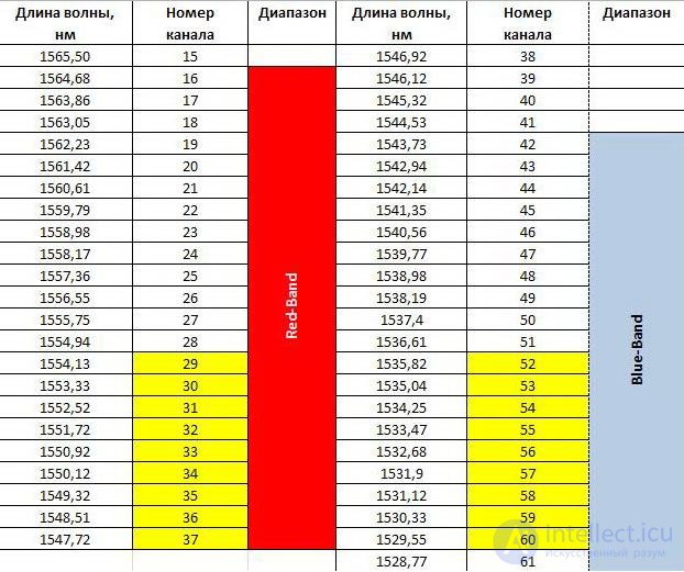
100 GHz grid.
The table on the right shows the grids of the 100 GHz frequency plan with various degrees of channel sparseness. All grids except the 500/400 one have equally spaced channels. Uniform channel spacing allows optimization of the operation of wavelength converters, tunable lasers, and other devices in an all-optical network, and also makes it easier to expand.
Implementation of one grid or another of the frequency plan largely depends on three main factors:
the type of optical amplifiers used (silica or fluorozirconate);
the transmission rate per channel – 2.4 Gbit/s (STM-16) or 10 Gbit/s (STM-64);
the influence of nonlinear effects.
Moreover, all these factors are strongly interrelated.
Standard silica-fiber EDFAs have one drawback – a large variation in gain in the region below 1540 nm, which leads to lower signal-to-noise ratios and gain nonlinearity in this region. Both very low and very high gain values are equally undesirable. As bandwidth grows, the minimum standard-permitted signal-to-noise ratio increases – for example, for an STM-64 channel it is 4–7 dB higher than for STM-16. Thus, the gain nonlinearity of silica EDFAs limits the usable band for STM-64 multiplex channels (1540–1560 nm) more strongly than for STM-16 and lower-capacity channels (where practically the entire gain band of a silica EDFA can be used, despite the nonlinearity).
50 GHz grid.
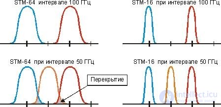
The denser, as yet non-standardized, 50 GHz frequency grid allows more efficient use of the 1540–1560 nm band in which standard silica EDFAs operate. Along with this advantage, this grid has its drawbacks.
First, as inter-channel spacing decreases, the influence of the four-wave mixing effect increases, which begins to limit the maximum length of an inter-regeneration line (a line based solely on optical amplifiers).
Second, the small inter-channel spacing of ~0.4 nm can limit the ability to multiplex STM-64 channels. As can be seen from the figure, multiplexing STM-64 channels with a 50 GHz spacing is not permissible, since overlap of the spectra of adjacent channels then occurs. Only when a lower per-channel transmission rate is used (STM-4 and below) does spectral overlap not occur.
Third, at a 50 GHz spacing, the requirements for tunable lasers, multiplexers, and other components become more stringent, which reduces the number of potential equipment manufacturers and also leads to an increase in its cost.
DWDM multiplexers (as opposed to more traditional WDM) have two distinctive features:
use of only a single transparency window at 1550 nm, within the C-band (1530–1560 nm) and L-band (1570–1600 nm) regions;
small spacing between multiplex channels, 0.8 or 0.4 nm.
In addition, since DWDM multiplexers are designed to work with a large number of channels – up to 32 or more – then, alongside DWDM devices that multiplex (demultiplex) all channels simultaneously, new devices are also allowed, having no analogs in WDM systems, that operate in a mode of adding or dropping one or more channels to/from the main multiplex stream represented by a large number of other channels. Since the output ports/poles of a demultiplexer are fixed to specific wavelengths, such a device is said to perform passive wavelength routing. Because of the small spacing between channels and the need to work with a large number of channels simultaneously, manufacturing DWDM multiplexers requires significantly greater precision compared to WDM multiplexers (which typically use the 1310 nm, 1550 nm transparency windows, or additionally the wavelength region near 1650 nm). It is also important to ensure high performance in terms of near-end (directivity) and far-end (isolation) crosstalk at the poles of a DWDM device. All this leads to a higher cost of DWDM devices compared to WDM.
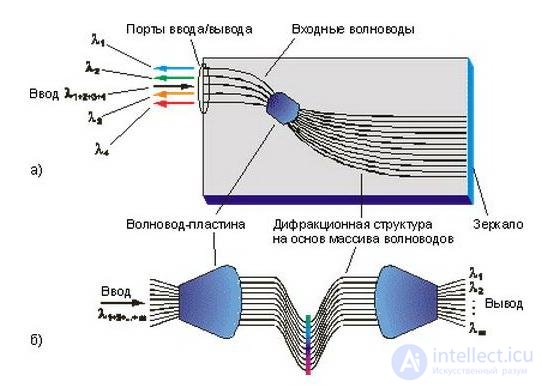
Figure "a" shows a typical diagram of a DWDM multiplexer with a mirror-reflective element. Let us consider its operation in demultiplexing mode. The incoming multiplex signal arrives at the input port. This signal then passes through a slab waveguide and is distributed among a set of waveguides forming an arrayed waveguide grating (AWG) diffraction structure. The signal in each waveguide remains multiplexed, and each channel remains represented in all waveguides. The signals are then reflected from the mirror surface, and as a result the light streams are again collected in the slab waveguide, where they are focused and interfere – forming spatially separated interference intensity maxima corresponding to different channels. The geometry of the slab waveguide, in particular the arrangement of the output poles, and the lengths of the AWG structure's waveguides are calculated so that the interference maxima coincide with the output poles. Multiplexing occurs by the reverse process.
Another way to build a multiplexer is based not on one but on a pair of slab waveguides (fig. b). The operating principle of such a device is similar to the previous case, except that here an additional slab is used for focusing and interference.
DWDM multiplexers, being passive devices, introduce significant attenuation into the signal. For example, the losses for a device (fig. 1a) operating in demultiplexing mode amount to 4–8 dB, with far-end crosstalk <-20 dB, and a signal spectral half-width of 0.05 nm.
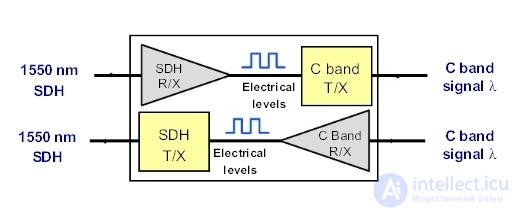
To transmit data on a wavelength from the DWDM grid, two types of devices can be used – DWDM transceivers and transponders. DWDM transceivers come in various form factors and can be used in passive DWDM solutions.
Unlike transceivers, transponders convert the emission wavelength of terminal equipment into a DWDM wavelength for transmission to the multiplexer. Optical signals whose parameters conform to the standards defined by Recommendation G.692 are fed to the inputs of the optical multiplexer. A transponder can have a varying number of optical inputs and outputs. But while any transponder input can be fed an optical signal whose parameters are defined by Rec. G.957, its output signals must conform in their parameters to Rec. G.692. In this case, if m optical signals are being multiplexed, then at the transponder output the wavelength of each channel must correspond to only one of them, in accordance with the ITU frequency grid plan.
The development of EDFA-based optical amplification technology has greatly changed the methodology for designing fiber-optic communication systems. Traditional fiber-optic systems use repeater-regenerators that boost signal power (fig. 3a). When the distance between remote nodes begins to exceed, due to signal attenuation conditions, the maximum permissible span length between adjacent nodes, additional regenerators are installed at intermediate points; these receive the weak signal, amplify it during optoelectronic conversion, restore the duty cycle, edges, and timing characteristics of the pulse train, and after conversion back to optical form transmit onward the correct amplified signal, in the same form it had at the output of the previous regenerator. Although such regeneration systems work well, they are quite expensive and, once installed, cannot increase the line's throughput.
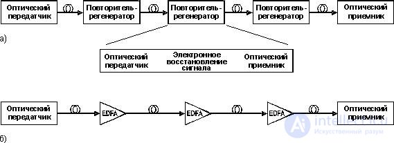
With EDFA-based systems, power losses in the line are overcome through optical amplification (fig. 3b). Unlike regenerators, this "transparent" amplification is not tied to the signal's bit rate, which makes it possible to transmit information at higher speeds and increase throughput until other limiting factors come into play, such as chromatic dispersion and polarization mode dispersion. EDFA amplifiers are also capable of amplifying a multichannel WDM signal, adding another dimension to throughput capacity.
+Although the optical signal generated by the source laser transmitter has a well-defined polarization, all other nodes along the path of the optical signal, including the optical receiver, must exhibit weak dependence of their parameters on polarization direction. In this sense, EDFA optical amplifiers, being characterized by weak polarization dependence of gain, have a noticeable advantage over semiconductor amplifiers.
Unlike regenerators, optical amplifiers introduce additional noise that must be taken into account. Therefore, along with gain, one of the important parameters of an EDFA is the noise figure.
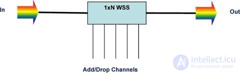
Using a Reconfigurable Optical Add/Drop Multiplexer (ROADM) enables flexible deployment and remote configuration of spectral channels. At any node of a ROADM network, it is possible to switch the state of a spectral channel to add/drop or through-transmission without interrupting active services. When working with a tunable laser, ROADM provides flexible control of spectral channels. ROADMs make it possible to build networks with multiple rings or mixed networks, based on wavelength selective switching (WSS) technology.
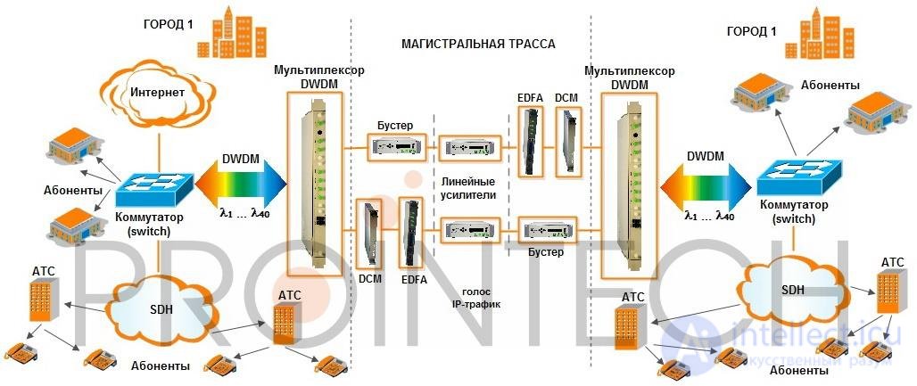
Metropolitan DWDM networks are typically built using a ring architecture, which allows protection mechanisms to be applied at the DWDM level with a recovery time of no more than 50 ms. It is possible to build a network infrastructure using equipment from several vendors, with an additional distribution layer based on Metro DWDM equipment. This layer is introduced to organize traffic exchange between networks with equipment from different vendors.
In DWDM technology, the minimum signal granularity is an optical channel, or wavelength. Using whole wavelengths with a channel capacity of 2.5 or 10 Gbit/s for traffic exchange between subnetworks is justified for building large transport networks. But transponder-multiplexers make it possible to organize traffic exchange between subnetworks at the level of STM-4/STM-1/GE signals. The distribution layer can also be built on SDH technology. But DWDM has a major advantage related to the transparency of control channels and service channels (for example, service communication). When SDH/ATM/IP signals are packaged into an optical channel, the structure and content of the packets do not change. DWDM systems only monitor individual bytes to verify correct signal transmission. Therefore, connecting subnetworks over a DWDM infrastructure on a single wavelength can be regarded as connecting them with a pair of optical cables.
When using equipment from different manufacturers, two data transmission subnetworks of one manufacturer are connected through a DWDM network of another manufacturer. A management system physically connected to one subnetwork can also manage the operation of the other subnetwork. If SDH equipment were used at the distribution layer, this would not be possible. Thus, on the basis of DWDM networks, networks from different manufacturers can be combined to transmit heterogeneous traffic.
SFP (WDM, CWDM, DWDM) – WHAT IS IT? WHAT IS IT FOR?
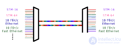
Wavelength division multiplexing is based on the method of multiplexing optical channels. The principle of this method is that each information stream is transmitted over a single optical fiber at a different wavelength (at a different carrier frequency), spaced 20 nm apart from one another.
Using special devices – optical multiplexers – the streams are combined into a single optical signal, which is launched into the optical fiber. At the receiving end, the reverse operation is performed – demultiplexing, carried out using optical demultiplexers. This opens up truly boundless possibilities both for increasing line throughput and for building complex topological solutions using a single fiber.
When choosing the number of channels, attention should be paid to the type of single-mode fiber used! For example, in G.652B type fibers (fiber with a water peak at 1383 nm), short wavelengths experience large radiation losses; as a result, the allowable transmission distance is reduced and the number of spectral channels will be lower than required.
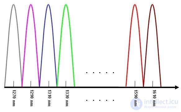
In Coarse WDM systems, in accordance with ITU Recommendation G.694.2, no more than 18 carriers with a 20 nm step should be used: 1270, 1290, 1310 … 1570, 1590, 1610, i.e., if the total required width of the wavelength range does not exceed 340 nm. It should be noted that attenuation at the edges of such a wide range is quite high, especially in the short-wavelength region. The number of channels was able to be increased to 18 thanks to so-called zero water peak fibers (ZWPF, Zero Water Peak Fiber; LWPF, Low Water Peak Fiber), whose parameters are defined by ITU-T Recommendation G.652.C/D. In fibers of this type, the absorption peak at 1383 nm is eliminated, and the attenuation at this wavelength is about 0.31 dB/km. G.653 fiber turned out to be unsuitable for the new, rapidly developing WDM technology due to zero dispersion at 1550 nm, which led to a sharp increase in signal distortion from four-wave mixing in these systems. The optical fiber best suited for dense and high-density WDM (DWDM and HDWDM) turned out to be G.655 fiber, and for coarse WDM – the recently standardized G.656 optical fiber . The creation of fibers without a "water peak" made it possible to use, in communication systems, all wavelengths in the range from 1260 to 1625 nm – i.e., precisely where silica optical fiber has the greatest transparency.
MAIN EQUIPMENT
Multiplexers/demultiplexers (MUX/DEMUX); allow optical signals to be combined and separated.OADM modules – add/drop multiplexers;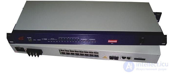
allow a signal on specific carrier frequencies to be dropped from and added to the fiber.
Depending on the task at hand, the configuration of the multiplexer/demultiplexer (Mux/Demux) is determined by the following characteristics:
Two-fiber multiplexer (2 fiber) Single-fiber multiplexer (1 fiber (single fiber) or bidirectional) 4- or 8-channel multiplexer (8 or 16 wavelengths) operating on a single fiber 8- or 16-channel, operating on two fibers multiplexer with two "common" (COMMON) outputs for implementing a "ring" topology For "Point-to-Point" or "Ring" topologies, a "paired" (Tx–Rx ports) set of multiplexers is required – Mux/Demux Type I , Mux/Demux Type II Connectors – FC, SC, LC, ST, FA, SA
Multiplexers can be supplied in the following design options: 19” rack-mount 1RU In a plastic housing (for wall mounting or installation in a splice closure) By connector type – LC, SC, etc.
SFP (Small Form Factor Pluggable) transceivers (SFP, SFP+, X2, XFP) – generate and receive optical signals (of specific wavelengths) in a CWDM system; convert the signal from electrical to optical and back. An SFP module combines both a transmitter and a receiver in one unit. It therefore supports simultaneous transmission and reception of data over two links within a single channel. Ever since the days of radio, such devices have been called transceivers. This is exactly why SFP modules are called transceivers.

Each SFP transceiver operates over two fibers and, unlike standard two-fiber 1000Base LX transceivers, operates on two different wavelengths – the wideband receiver works with one wavelength and the transmitter with another. To form a data channel, SFP transceivers are supplied "in pairs."
Transceivers also differ in signal power (reach), i.e., they operate over different distances.
For denser multiplexing of the optical signal, "colored" SFP modules are used, operating in a specific wavelength range (CWDM). Such SFP transceivers are designed to generate optical signals on "main carriers" from 1270 to 1610 nm (20 nm step).
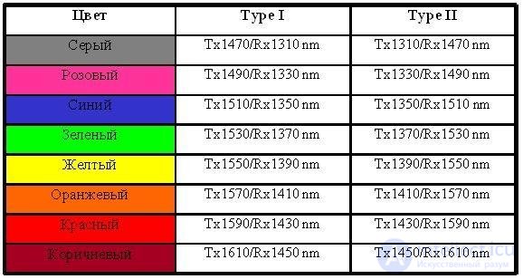
SFP
SFP modules are available operating over either one or two fibers, with throughput of 1.25, 2.5, and 4.25 Gbps. These modules can be installed directly into switching equipment from practically any manufacturer, making seamless integration of CWDM into an existing infrastructure possible. The same module can serve as a Gigabit Ethernet, Fibre Channel, or SDH interface, which significantly adds flexibility to the solution.
It is also possible to install CWDM SFP modules in media converter chassis. Using a chassis is the most flexible solution, completely eliminating equipment incompatibility issues. Using a chassis, you get standard 1000BASE-T Gigabit Ethernet ports at the output, which allows you to avoid expensive switches with SFP ports.
Special attention should be paid to multiplexing 10 Gbit/s channels. As recently as three years ago, there were no transceivers operating at 10 Gbit/s speeds and supporting the wavelength grid of coarse wavelength division multiplexing systems; such modules have now appeared, however their use imposes significant limitations on system capabilities compared to multiplexing 1.25 Gbit/s and 2.5 Gbit/s channels.
Currently there are no lasers supporting a speed of 10 Gbit/s and operating in the 1350–1450 nm wavelength range, so the maximum number of multiplexed 10 Gbit/s channels cannot exceed 12 when using two G.652D standard fibers. In addition, when using 10 Gbit/s channels, it must be taken into account that the maximum optical budget of such modules is currently no more than 28 dBm, which corresponds to a reach of approximately 80 kilometers over single-mode fiber. In cases where it is necessary to multiplex and transmit more than 12 channels of 10 Gbit/s, including over distances greater than 80 kilometers, DWDM equipment is used.
OADM modules – add/drop multiplexers; allow a signal on specific carriers to be dropped from and added to the fiber.
Main properties: Add/drop of a single channel Passive optics Low insertion loss for through channels Dedicated wavelength for the end user
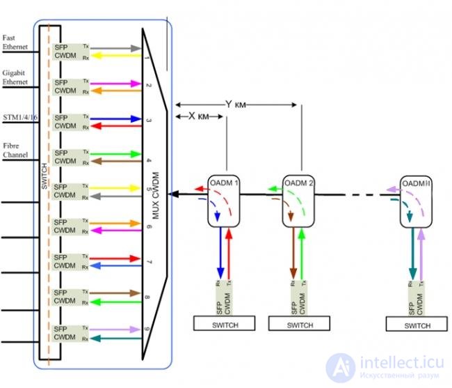
In principle, single-channel and two-channel OADM modules are distinguished. Their difference lies in the ability to receive and obtain an optical signal from one or two multiplexers, and is physically due to the presence of one or two transceiver units. Accordingly, a single-channel OADM module has one transceiver unit and can only work with one multiplexer "in one direction." A two-channel OADM module has two transceiver units and can work "in two directions" with two multiplexers / demultiplexers.
The transceiver unit of a single-channel OADM module has four interfaces:
Com port – receives the signal from the multiplexer side Express port – passes the signal on to other elements of the system Add port – adds a channel at a specific wavelength into the line, Drop port – extracts a channel at a specific wavelength from the line.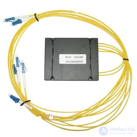
Such devices have no protocol or bandwidth restrictions. Accordingly, a two-channel OADM module has two additional ports, Add and Drop. When using a two-fiber system, the Com2 and Express2 ports are also added. A single-channel OADM module works in tandem with one SFP transceiver, a two-channel OADM – with two
The terminal-transit OADM module (drop/pass module) drops one channel from the backbone and directs it to the local port. The remaining channels are passed directly to other nodes of the network.
The single-channel OADM multiplexing module (drop/add module) has two local interfaces. The first drops one channel from the backbone and directs it to the local port, the second – adds this channel back into the backbone in the opposite direction. Such a module is required when building a "ring" topology network.
OADM modules can be supplied in the following design options: 19” rack-mount 1RU In a plastic housing (for wall mounting or installation in a splice closure) Connectors – LC, SC, etc.
The main wavelength division multiplexing systems are:
So what is WDM?
A technology for combining optical signals of different wavelengths transmitted simultaneously over a single fiber, 2 or more signals separated at the far end by wavelength. The most typical (2-channel WDM) combines wavelengths of 1310 nm and 1550 nm in a single fiber.
Two-channel WDM (and three-channel) can be used to quickly and simply add an additional (or two additional) wavelength(s). It is very simple to install and connect and very inexpensive. In most cases, WDM is the most economical solution when there is a shortage of fiber in a cable, providing a fiber savings of 2 to 1 or 3 to 1 by combining wavelengths of 1310 nm, 1550 nm, and 1490 nm in a single fiber.
SWDM
In cases where more channels are required to expand an existing fiber-optic infrastructure, CWDM provides an efficient solution for short optical spans (up to 80 km). CWDM can simply and quickly add up to 18 additional wavelengths at standardized ITU frequencies. It is ideal for moderately sized networks with spans of up to 100 km. Since the spacing between wavelengths is 20 nm, less expensive lasers can be used, providing very low cost. CWDM systems, although multichannel, have no optical amplification mechanisms, and the range limitation is determined by the channel with the maximum attenuation. Moreover, channels in the region from 1360 nm to 1440 nm may experience the greatest attenuation (1 to 2 dB/km) due to the water peak in this region for some types of optical cable.
Where high capacity or long-distance transmission is required, DWDM solutions are the preferred method for increasing fiber capacity. With its high-precision lasers, optimized for operation in the 1550 nm window (to reduce losses), DWDM systems are the ideal solution for more demanding networks. DWDM systems can use EDFAs to amplify all wavelengths in the DWDM window and increase transmission length up to 500 km.
DWDM systems are typically limited in range to 4–5 amplification spans due to amplified spontaneous emission (ASE) noise in EDFAs. Simulation tools are available that make it possible to accurately determine how many EDFAs can be installed. On long spans (> 120 km), dispersion can create problems, requiring the installation of dispersion compensation modules. The DWDM band is limited to wavelengths from 1530 nm to 1565 nm by the EDFA gain range.
Types of solutions:
1. Point-to-point.
Adding a spectral system with a "point-to-point" topology to an optical system is a simple and cost-effective solution to the problem of fiber shortage. 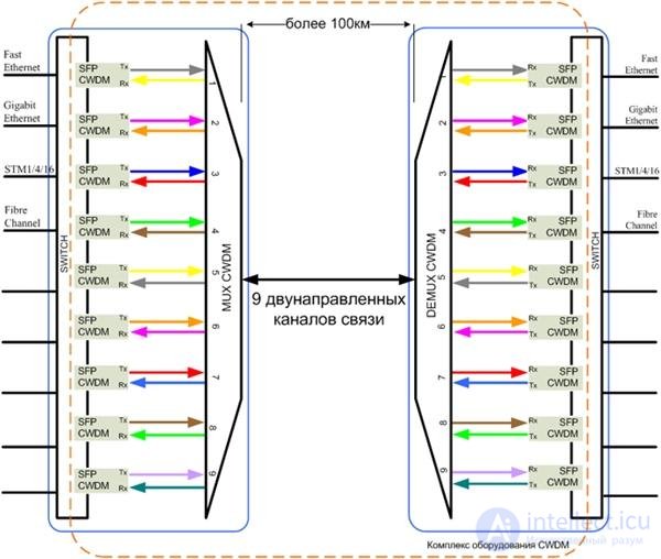 Systems with this kind of topology are typical for solving the problem of simultaneously transmitting a large number of data streams to increase the number of services provided (video, voice, etc.). In this case, fibers of the already existing optical transport network are used. In this mode of operation, information is transmitted over channels between two points. For successful data transmission over a distance of up to 50–80 km, multiplexers/demultiplexers are needed at the nodes where the information streams will be combined and subsequently separated.
Connection with branches
This architecture implements the transmission of information from one node to another with intermediate nodes along the way, where individual channels can be added and dropped using OADM modules. The maximum number of branches is determined by the number of duplex transmission channels (for example, 4 or  ) and by the optical budget of the line. In calculations, it must be kept in mind that each OADM module introduces attenuation, as a result of which the total path length is correspondingly reduced. An optical channel can be extracted at any point along the path.
In this case, OADM modules (two-channel) are installed between two multiplexers / demultiplexers. Each two-channel OADM module must be equipped with two SFP transceivers. 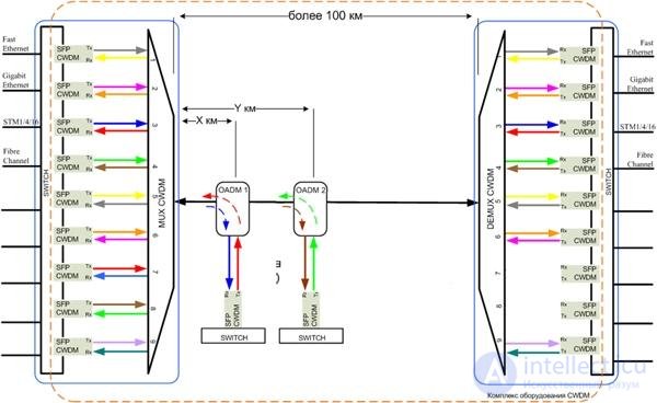
Point with branches.
The fundamental difference from the first option is the absence of a second multiplexer / demultiplexer. Thus, signal exchange takes place between the central communication node and terminal equipment at different points along the line. This architecture appears promising from an economic point of view, since it effectively makes it possible to eliminate an aggregation-layer switch from the network while achieving significant fiber savings. In this case, the distance from the (single-channel) OADM module to the location of the terminal equipment (switch, router, media converter) is limited only by the signal power in the line and the insertion losses introduced by the multiplexing equipment.
Advantages Fiber savings — a wavelength division multiplexing system allows up to 8 channels with a throughput of up to 2.5 Gb/s per channel to be transmitted over a single fiber Independence from power supply — power is only needed for active equipment No issues with "crashes," reboots, etc. No need to organize permanent access to locations where system elements are installed — OADM modules exist in designs for installation in optical splice closures Reduced impact of the "human factor" – absence of active components requiring configuration, management, etc. Significant reduction in total cost of ownership — reduction in operating expenses Relatively low cost, possibility of eliminating aggregation-layer equipment Maximum operating range is 80 kilometers or more Independence from client protocols – transmission of up to 18 independent services over two pairs of optical fibers; transparency for all data transmission protocols Availability of various types of equipment for installation under different conditions: rack-mount, splice closure, wall-mount.
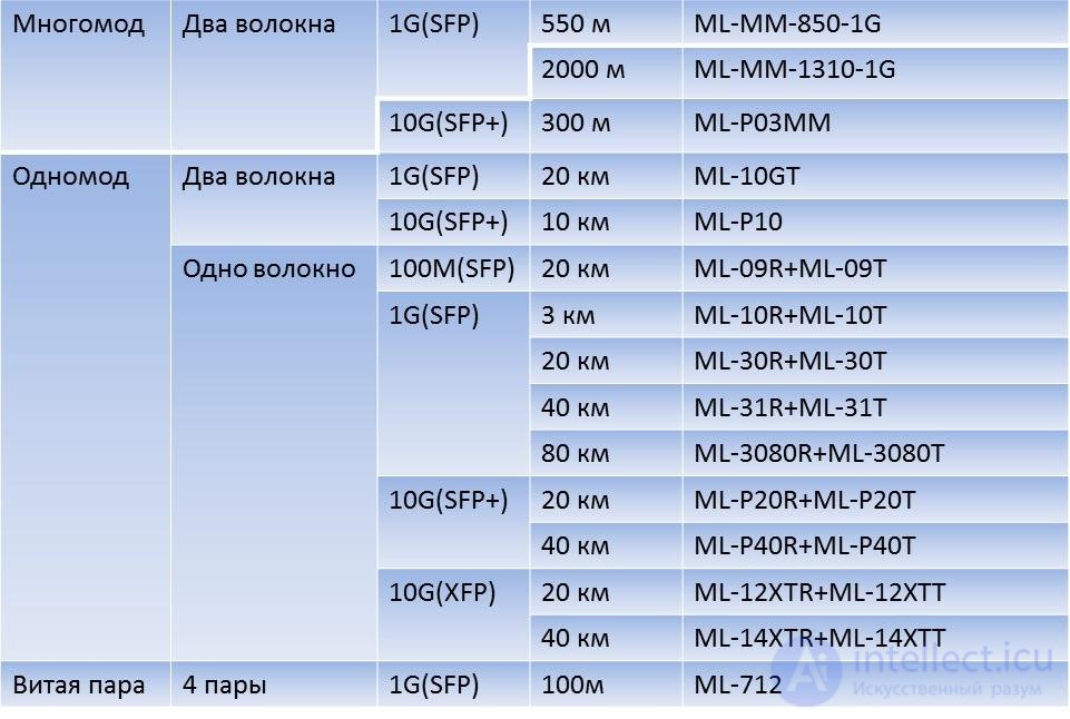
Table for selecting an MLaxLink module part number
In this article, you will find a table for selecting an MLaxLink module according to your requirements.
We hope it will be a good tool and save you valuable time.
The first thing you need to know is the type of optical fiber you are using, the number of fibers; then, knowing the required module speed, interface, and reach, you can use the table to select the module you need.
The ML-712 module is listed separately in the table, as the only and universal solution for copper cable.
WDM — Wavelength Division Multiplexing (Channel wavelength multiplexing). This is a technology that allows several "streams" of an optical signal to be combined into a single optical fiber. Each stream is carried on its own wavelength.
Wavelength is often called "color," although light waves longer than 740 nm are not perceived by the human eye, and a person is unable to distinguish these colors. Some animals can see this light; for example, some snakes would be able to distinguish light at 1310 nm and 1550 nm.
WDM modules are usually called "one-eyed," although there are more exotic terms as well, such as "cyclops."
Let's understand how this works using an example. First, let's look at a regular optical module, for example, the ML-10GT (http://mlaxlink.ru/products/5/38/). Its operating principle is shown in Figure 1. Two optical fibers are used to transmit the signal. One fiber in one direction, the second in the other. In this case, light of the same color, 1310 nm, is used in both directions. This color is shown in blue in the figure.

Figure 1. Operation of ML-10GT modules
Suppose you don't have two fibers, but only one. How do you transmit a signal over a single fiber? There are several ways.
The first is to split the signal power at the ends of the line. Getting ahead of ourselves, we can say that nothing good will come of this. You could place an optical splitter at the ends of the line. The operating principle of this device is simple: the signal is split from one fiber into two, with the power usually divided equally. During operation, a lot of multiply-reflected light will arise in the line, and this line will most likely not work (although there are examples of successful use of this solution). It's a dead end, although optical splitters are actively used in PON technologies, but that is a topic for a separate article, or even a series of articles.
The second method can confidently be called workable. You can use a property of light such as polarization. For example, by changing the polarization of light immediately after it is emitted at the start of the line, you can filter out this signal at the end. In this case, it is indeed possible to transmit a signal in both directions over a single fiber, but devices for changing polarization are quite expensive, and such a solution is rarely used.
And finally, the third method, which has become the most widespread. It consists in using light of different wavelengths to transmit the signal in different directions. Light of different wavelengths can be easily separated. We all studied in school and remember Newton's Prism. For those who don't remember it well, see figure 2.
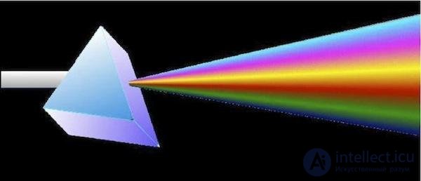
Figure 2. Newton's Prism
This method is already more than 300 years old. The device that separates light depending on wavelength is that very same prism, just more complex, and is called an "optical multiplexer/demultiplexer."
This technology is so popular that most optical transceivers installed today use WDM technology. The most popular are SFP WDM transceivers with a transmission range of up to 3 kilometers. At MLaxLink, these are the ML-10T and ML-10R (http://mlaxlink.ru/products/5/34/ andhttp://mlaxlink.ru/products/5/35/).
These transceivers use light with wavelengths of 1310 nm and 1550 nm to transmit the signal in different directions. One of the modules uses a 1310 nm transmitter, the other 1550 nm. However, when using these transceivers, there are peculiarities compared to "two-eyed" modules. WDM modules are installed in pairs, and only in pairs do they function correctly.
Those involved with this equipment not only technically but also financially should know that the different halves of such a transceiver pair often have different prices, since they have different production costs. Although at MLaxLink the price for the different "halves" is the same – we are convinced that this is simpler from every point of view.
Figure 3 clearly shows the operating principle of these modules.

Figure 3. Operation of ML-10T and ML-10R modules
Notice that the release lever has plastic of a certain color on it. This is very convenient, since you can determine the type of module without removing it from the equipment. It's a shame that not all manufacturers have this "nice little touch."
By the way, the colors are not chosen at random, but based on certain rules; each color on the lever corresponds to a specific transmitter wavelength.
List of correspondence between module colors and transmitter wavelengths:
|
850nm |
Black |
|
1310nm |
Blue |
|
1490nm |
Purple |
|
1550nm |
Yellow |
Examples of markings are shown in figures 4 and 5.
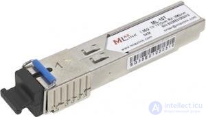
Figure 4. Blue module, 1310 nm
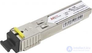
Figure 5. Yellow module, 1550 nm
In some cases, wavelengths other than 1310 nm and 1550 nm are used. For example, for SFP+ modules at ranges up to 40 km, gray is used for 1270 nm and turquoise for 1330 nm. These modules can be seen in figures 6 and 7.
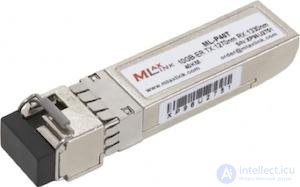
Figure 6. Gray module, 1270 nm
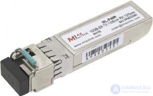
Figure 7. Turquoise module, 1330 nm
Solutions such as CWDM and DWDM also exist, which allow more than two streams to be transmitted over a single optical fiber and achieve tremendous speeds. Read about these technologies in our upcoming articles.
Wavelength Division Multiplexing (WDM) is a relatively new optical (or spectral) multiplexing technology that was developed in the 1970s-1980s. Today, WDM plays the same role for optical synchronous systems that Frequency Division Multiplexing (FDM) plays for analog data transmission systems. For this reason, systems with WDM are often called Optical Frequency Division Multiplexing (OFDM) systems. However, in essence these technologies (FDM and OFDM) differ substantially from one another. Their difference lies not only in the use of an optical (OFDM) or electrical (FDM) signal. FDM uses a single-sideband (SSB) AM modulation mechanism with a chosen system of subcarriers, whose modulating signal is identical in structure, since it is represented by a set of standard voice-frequency channels. In OFDM, the modulation mechanism needed in FDM to shift carriers is not used at all; the carriers are generated by separate sources (lasers), whose signals are simply combined by a multiplexer into a single multi-frequency signal. Each of its components (carriers) can in principle carry a digital signal stream formed according to the rules of various synchronous technologies. For example, one carrier might formally carry ATM traffic, another SDH, a third PDH, and so on. For this, the carriers are modulated with a digital signal in accordance with the traffic being transmitted.
Formally, for WDM systems it does not matter what coding and signal formation methods were used for a particular digital signal. Although, as a rule, the same type of traffic is transmitted in these systems, which is dictated by the synchronization methods used and the uniformity of the processing. Unlike SDH systems, the transported signal is not packaged into containers and is not processed according to the SDH multiplexing structure to form an STM-N transport module, which alone can be transmitted through the physical layer into the communication channel (transmission medium). If we simplify and represent the multi-layer interaction model of the main technologies – SDH/SONET, ATM, IP (without considering the possibility of transporting IP over ATM) – which carry out signal transport in global digital networks, together with WDM, then before the latter appeared it had the form shown in fig. 4.4-1a. The model consisted of three layers and the optical transmission medium and showed that in order to transport upper-layer traffic (ATM and IP) over the optical transmission medium, it had to be placed (encapsulated) into STM-N/OC-n transport modules of SDH/SONET technologies, capable, using the physical interface of these technologies, of passing through the physical layer into the optical transmission medium. From this, the need was clear for creating technologies for encapsulating ATM cells, for example, into SDH virtual containers (ATM over SDH), or IP packets into SONET virtual tributaries (IP over SONET). This was the work of the relevant standardization subcommittees at institutions such as ANSI, ISO, ITU-T, and ETSI, developing standards for these technologies.
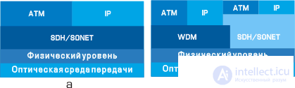
Fig. 4.4-1
After the appearance of WDM systems, the model takes the form shown in fig. 4.4-1b. Now the model has four layers, not counting the optical transmission medium. An intermediate WDM layer has appeared, which, like SDH/SONET, provides a physical interface, allowing not only SDH/SONET technology but also ATM and IP technologies to reach the optical transmission medium through the physical layer. In the latter case, encapsulation of ATM cells or IP packets into an intermediate SDH/SONET transport module is not required, which not only simplifies the process of handling and transporting traffic generated by ATM and IP systems, but also significantly reduces the total length of headers (which are appended as traffic passes from the upper layer to the lower layer), increasing the percentage occupied by the informational component of the traffic in the total length of the transmitted message, and hence the overall transmission efficiency. Naturally, ATM and IP traffic can also be transmitted via the traditional scheme using SDH/SONET, whose traffic can also be transmitted using WDM systems, which preserves the continuity of old transport schemes and increases the flexibility of composite WDM-SDH/SONET systems as a whole.
The basic diagram of a WDM system (four channels are taken as an example) has the form shown in fig. 4.4-2 (one forward channel is shown).
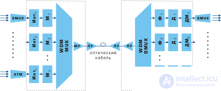
Fig. 4.4-2
Here, n input data streams (encoded digital pulse sequences) modulate (baseband modulation) optical carriers with wavelengths li using optical modulators Mi. The modulated carriers are multiplexed (combined) using a WDM Mux multiplexer into an aggregate stream, which, after amplification (using a booster or a high-power amplifier – MU), is fed into the OF (optical fiber). At the receiving end, the stream from the OF output is amplified by a preamplifier – PU, demultiplexed, i.e., separated into constituent streams – modulated carriers li, which are detected using detectors Di (bandpass filters Fi may additionally be used at their input to reduce crosstalk and thereby increase detection noise immunity), and, finally, are demodulated by demodulators DMi, forming at the output the original encoded digital pulse sequences. In addition to the MU and PU, line amplifiers – LU – can also be used in the system (as discussed above).
Wavelength multiplexing has been in practical use for more than 10 years and was initially aimed at combining two main carriers, 1310 nm and 1550 nm (the 2nd and 3rd transparency windows), in a single fiber, which made it possible to double the system's capacity and was justified by the entire history of fiber-optic line development. Many standard SDH systems offer this today as one of the configuration options. A number of researchers call such systems wideband WDM (wavelength spacing of 240 nm) as opposed to narrowband WDM (in which the spacing was an order of magnitude lower – 24-12 nm, which made it possible to fit 4 channels into the 3rd window (1550 nm)). This division of systems now seems not entirely correct, since in such "wideband" WDM the spectrum did not overlap but consisted of two isolated bands. On the other hand, a class of truly wideband WDM systems is now forming, overlapping in adjacent transparency windows (the 3rd and 4th) a band of about 84 nm from 1528-1612 nm. In the future, this class may possibly cover the 1280-1620 nm band, if we look at the characteristics of a pioneer in this field, the WaveStar AllMetro DWDM System from Lucent Technologies, which uses fiber that eliminates the absorption peak in the region of the 5th window (~1383 nm).
продолжение следует...
Часть 1 Choosing backbone WDM transmission equipment

Comments