Lecture
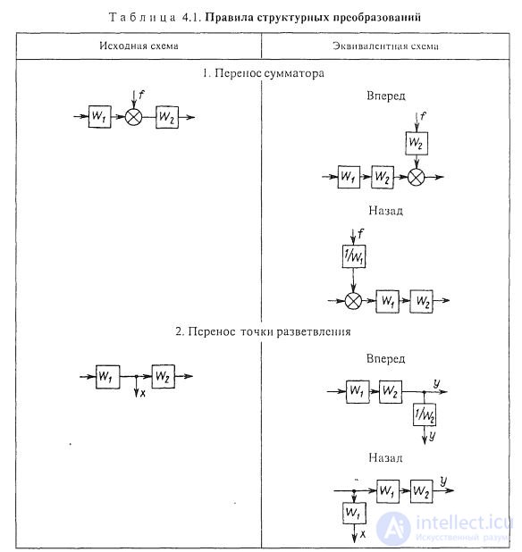
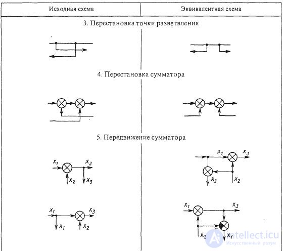
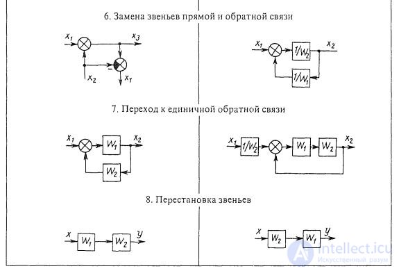
Structural transformation rules
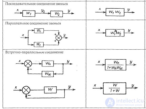
Consistent connection of links. With a series connection of links (Fig. 1.8, a), the output value of the previous link is the input value of the next link. The transfer function of the system of serially connected links is equal to the product of the transfer functions of the individual links:
W c (p) = W 1 (p) * W 2 (p) * W 3 (p) 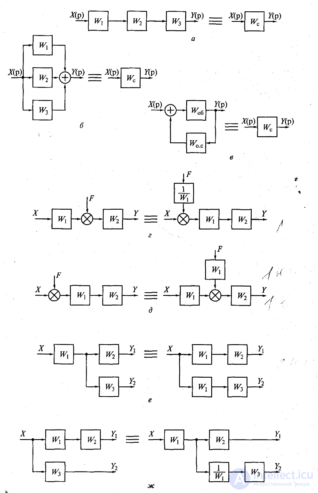
Fig. 1.8. Types of structural transformations:
a - the transformation of the transfer functions of the sequential inclusion of three links in the transfer function of one equivalent link; b - conversion of transfer functions of parallel connection of three links into transfer function of one equivalent link; c - the transformation of the transfer functions of the counter-parallel inclusion of two links into the transfer function of one link; g - movement of external influence from the middle of the circuit to the input; d - movement of external influence from the entrance to the middle of the scheme; e - moving the output signal from the middle of the circuit to the input; W - moving the output signal from the input to the middle of the circuit.
Parallel link links. The input value of a system consisting of parallel-connected links (Fig. 1.8. B) is simultaneously applied to the inputs of all links, and its output value is equal to the sum of the output values of the individual links. The transfer function of a system consisting of parallel-connected links is equal to the sum of the transfer functions of these links:
W c (p) = W 1 (p) + W 2 (p) + W 3 (p)
Counter-parallel link links. When counter-parallel connection of links to the connection input simultaneously with the input value of the system, its output value is passed, passing through the feedback link with the transfer function W oc (р) (Fig. 1.8, c). The transfer function of the system is determined by the expression:
W c (p) = 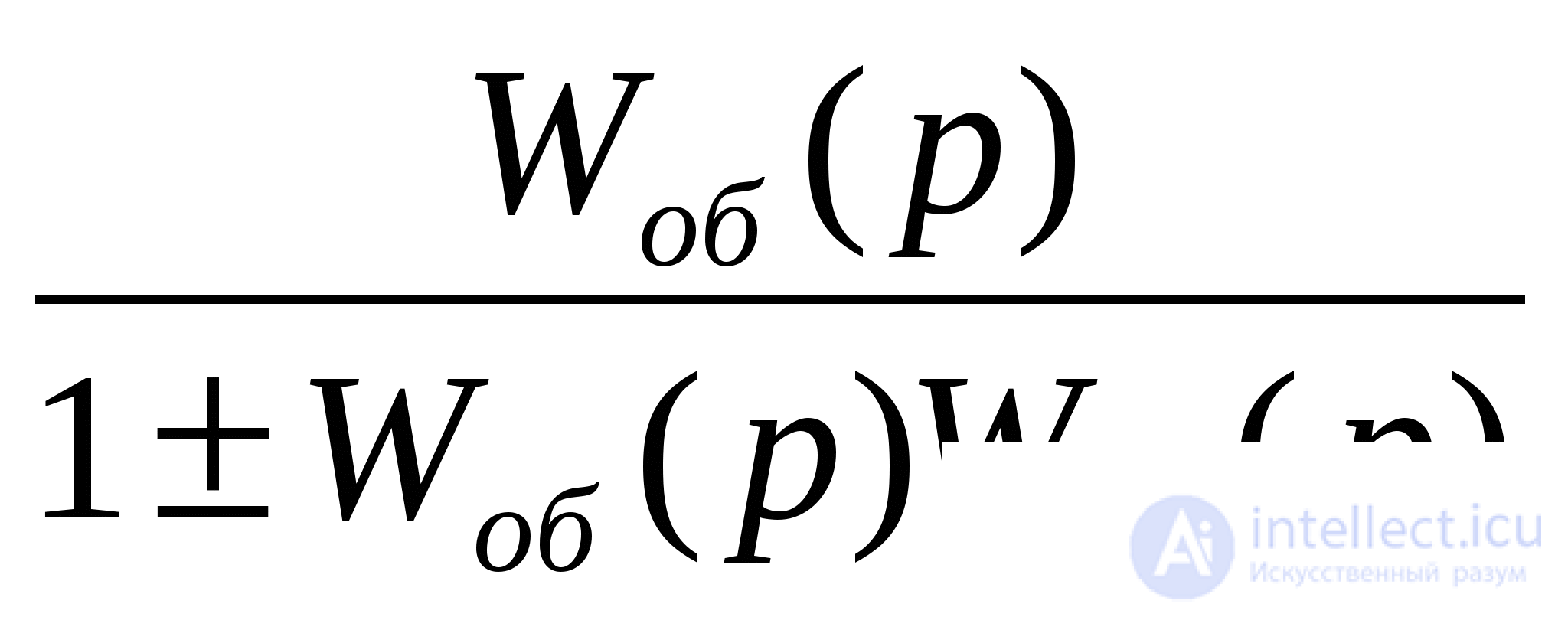
In the denominator, the “+” sign refers to negative feedback, the “-” sign refers to positive feedback. In industrial systems, mainly negative feedback is applied.
The circuit with negative feedback in the case of parallel-opposite connection of links is shown in Fig. 5.6, a. In fig. 5.6, b is given a diagram of connecting two links with a positive OS. 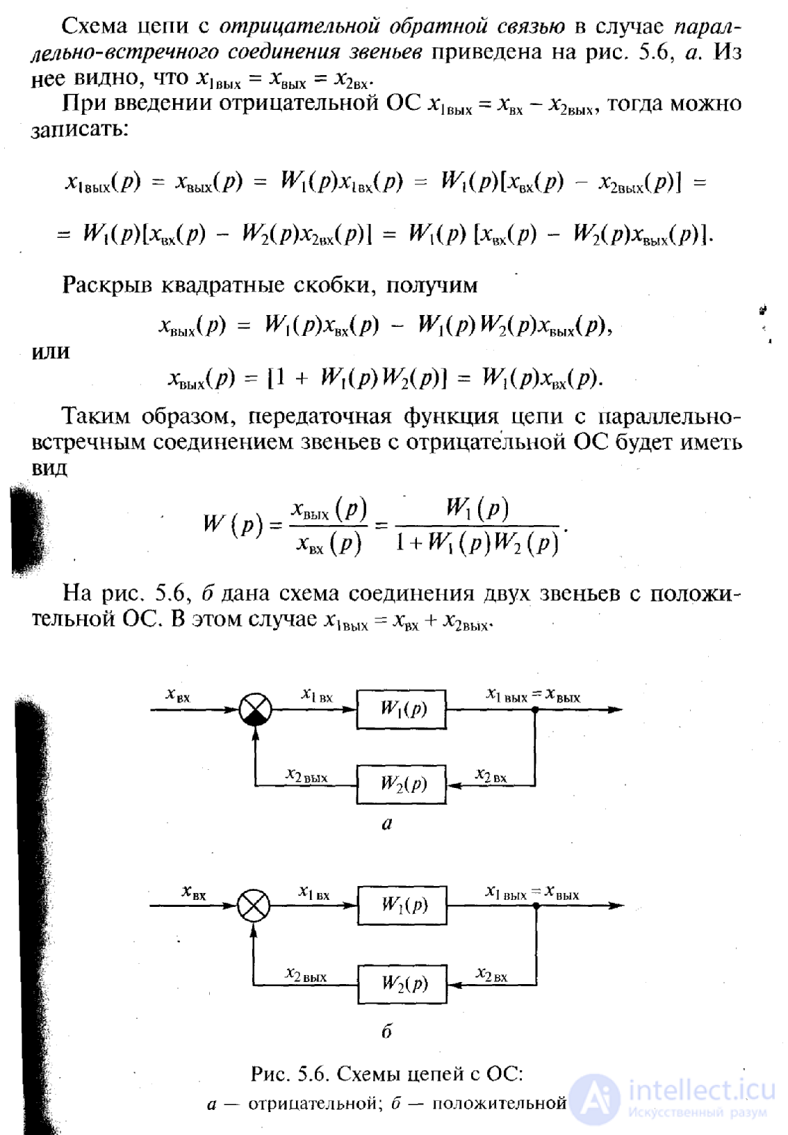
Thus, the breakdown of a differential equation defining the automatic control process in the system into differential equations of elementary links in the general case can be performed in various ways. Consequently, the same control process can be carried out using systems divided into different numbers of elementary units with different structural links between them. Having as a source any one of such systems and determining the transfer functions of all its elementary links, you can further simplify the structural scheme of the system by its equivalent transformations. In all the various structural schemes obtained as a result of equivalent transformations of the original scheme, the transfer function of the system as a whole does not change and does not depend on how much and on what elementary links the system is divided and what structural links exist between its links.
The following transformations can be added to the already given transformations of structural schemes. External influence F applied to the output of the link with the transfer function W 1 (Fig. 1.8, d), it is possible to transfer to its input by placing an additional link with the transfer function 1 / W 1 between the action and the input of the link. The external impact F applied to the input of the link with the transfer function W 1 can be transferred to its output (Fig. 1.8, d) by placing an additional link between the impact and the output of the link with the same transfer function W 1 . The point of attachment of any structural connection to the output of a link that has a transfer function W 1 can be transferred to its input by including in this connection an additional link with the same transfer function W 1 (Fig. 1.8, е). The point of attachment of any structural connection to the input of a link with transfer function W 1 (Fig. 1.8, g) can be transferred to its output by including in this connection an additional link with transfer function 1 / W 1 .
Using the above rules, cross-link structural patterns can be transformed into non-crossover structural circuits, replace multi-loop automatic control systems with single-loop ones, and also select the linear part in non-linear automatic control systems.
These rules are best explained with examples. In fig. 1.9, and shows the initial structural diagram of the system, which has an intermediate connection. This system can be converted to the form shown in Fig. 1.9, b, which allows the use of previously obtained ratios. The transformed block diagram has two feedbacks, one of which, including links with transfer functions W 3 and W 5 , covers the link with transfer function W 2 , and the second, consisting of links with transfer functions W 3 and W 4, forms the main feedback. Consequently, the link with the transfer function W 3 was included in the block diagram twice. Applying further the rules for calculating equivalent transfer functions, we arrive at a simple block diagram of a single-loop automatic control system (Fig. 1.9, c), in a straight chain of which there is a link with a transfer function
W c = W 1 W 2 / (1- W 2 W 3 W 5 ), (1-9)
and in the feedback circuit
W oc = W 3 W 4. (1-10)
It should be noted that with sufficient experience it is possible to establish the presence of such feedbacks without constructing the structural scheme shown in Fig. 1.9, b.
The transformation of the block diagrams of automatic regulation systems with cross-feedback leads, as a rule, to the introduction of links with inverse transfer functions into the transformed block diagram. Thus, the block diagram of a system with such feedbacks (Fig. 1.9, d) can be converted to the form shown in Fig. 1.9, d. From this figure it is clear that the main feedback of this system has a link with the transfer function 1 / W 1 . After such a transformation, the regulatory system can be reduced to a single-loop (see Fig. 1.9, c). The transfer function of a link in a straight chain is defined as
W 0 = 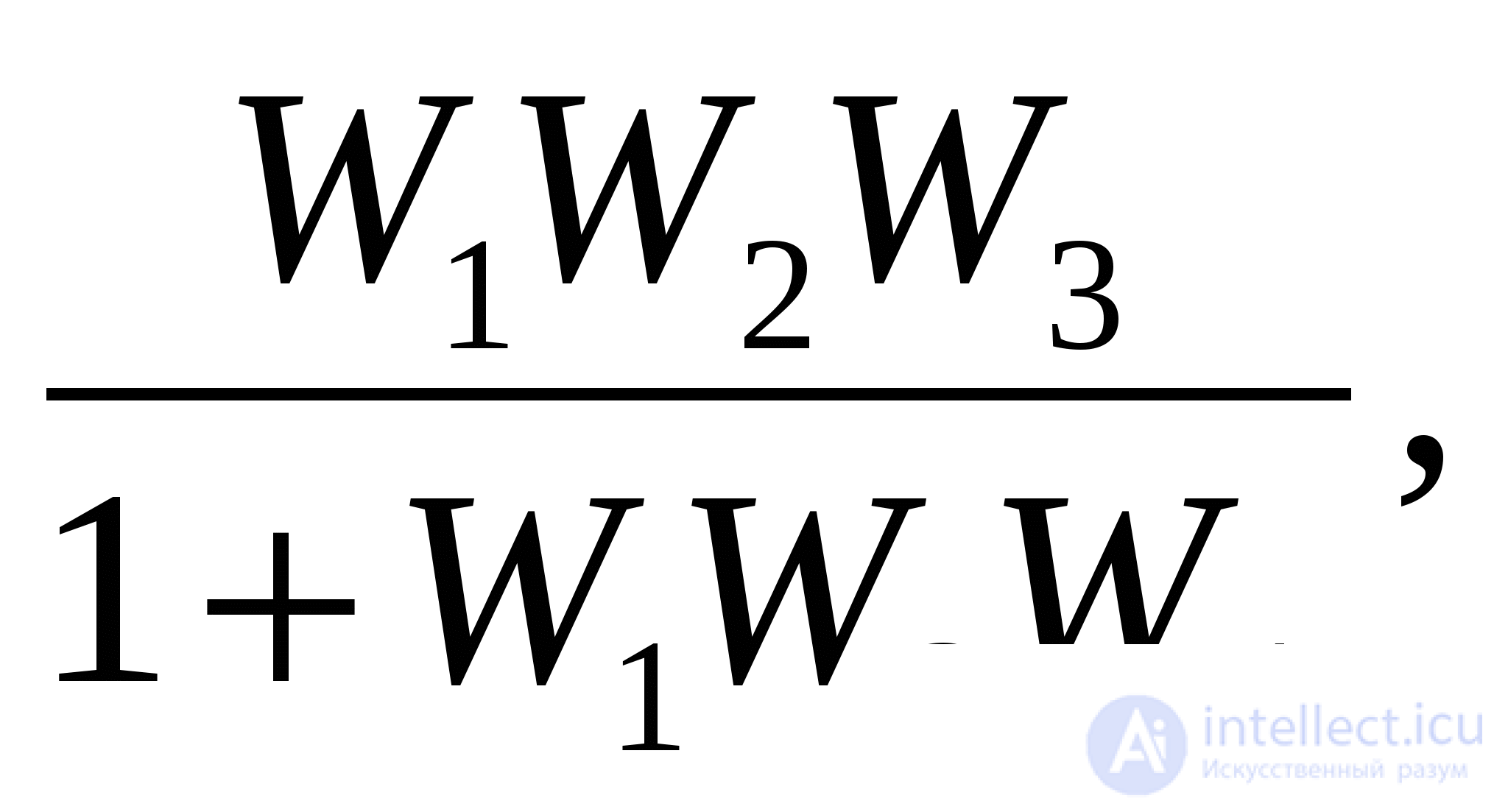
and in the feedback circuit
W oc = W 5 / W 1 .
The application of rules for the transformation of structural diagrams of automatic control systems and the determination of equivalent transfer functions greatly simplifies the analysis of such systems. However, in experimental studies of dynamic systems, the inverse problem often arises - finding the transfer function of a link, when the transfer functions of the system as a whole and the rest of its links are known. Such a problem is solved using the previously discussed rules. 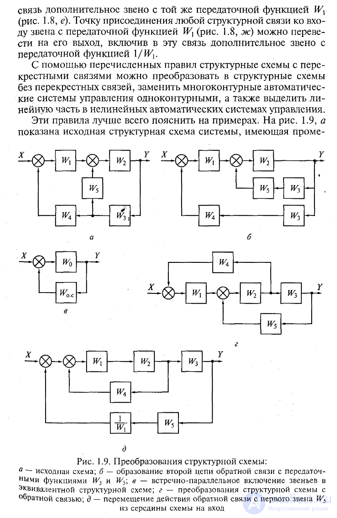
Figure 1.9. Structural Transformations
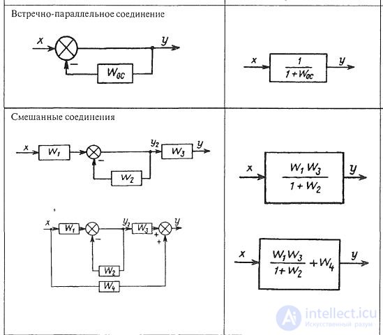
With a parallel counter-inclusion, there may be a special case Z ( p ) = 1 , the transfer function of the system for the output value:
X out (p) / X in (p) = W (p) / 1 + W (p),
For the error: X (p) / X in (p) = 1/1 + W (p).
If W (p) = A (p) / B (p), then
for the output value X output (p) / X I (p) = A (p) / A (p) + B (p),
For the error: X (p) / X in (p) = B (p) / A (p) + B (p).
Complex link links. In fig. 1.10 shows a diagram of a complex connection of links in the ACS, on which it is easy to see typical connections. The first and second links here are combined in block I with a parallel-matched connection, the fifth and sixth in block III with a serial connection. In block II, the fourth link is allocated, covered by its own positive OS. It is conditionally possible to accept that a proportional link with a gain equal to one is included in this OS. We write the transfer functions of the selected blocks: 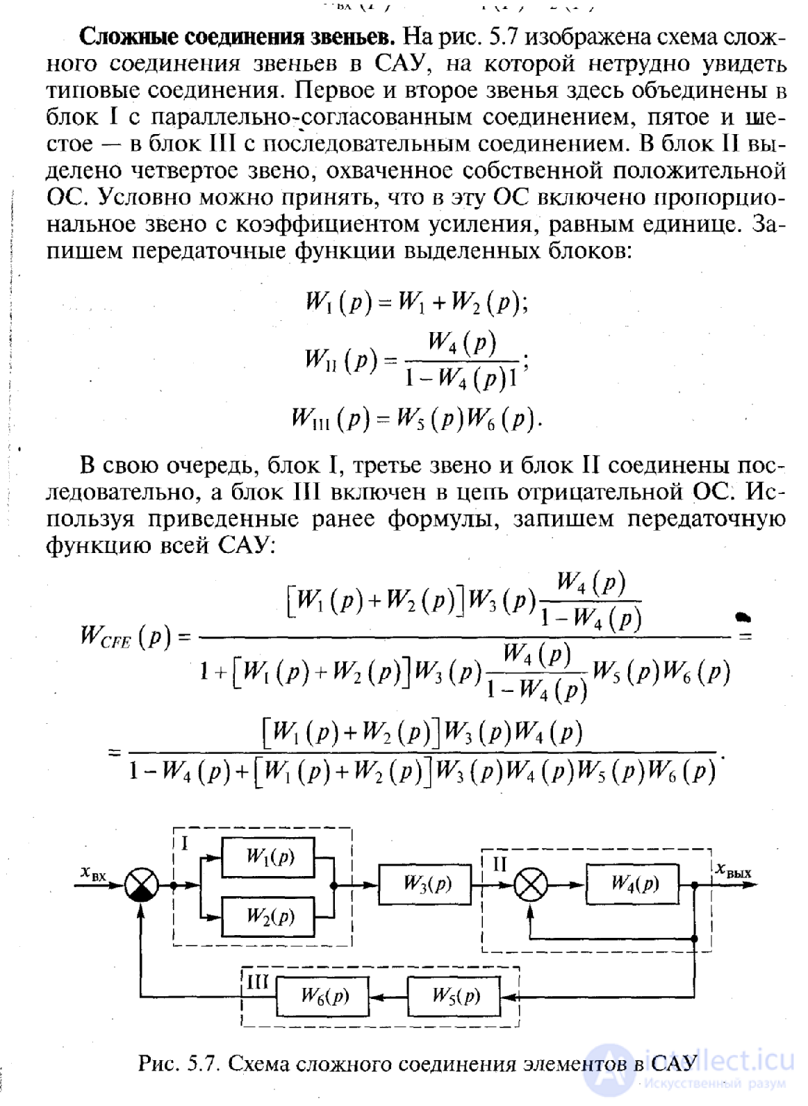
In turn, block I, the third link and block II are connected in series, and block III is connected to the negative feedback circuit. Using the above formulas, we write the transfer function of the entire ACS:
Figure 1.10. The scheme of a complex connection of elements of ACS
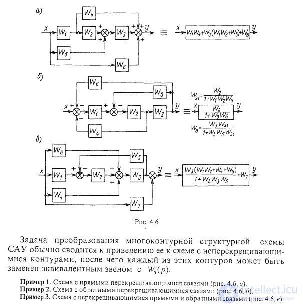
The task of converting a multi-contour structural scheme of ACS is usually reduced to bringing it to a scheme with non-intersecting contours, after which each of these contours can be replaced by an equivalent link with We (p).
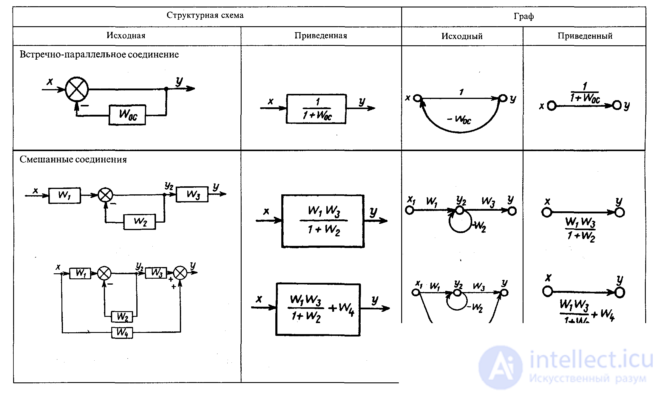
The transfer functions of complex ACSs can be determined by the structural scheme and without reducing it to a single loop by applying signal transmission diagrams (from graph theory). Signal transmission graphs are similar to block diagrams and are also used to visualize mathematical dependencies in ACS (see Fig. 4.1). The directional signal (oriented) graph (the direction of the signal is indicated) is a more compact form of recording structural diagrams. The rules for graph conversion are similar to the rules for the transformation of structural schemes (see Table 1).
A graph is a collection of vertices (nodes), beginning, end, and edges. The edge (branch, arc) is identically equal to the operator W (p). The vertices of the graph are variables (signals): y, u, x , etc. In the general case, the edges are the coefficients a, b , c, Ti , ki, etc. in the ACS equations; the arc is directed and characterized by the symbol k ( W ) (the weight of the arc).
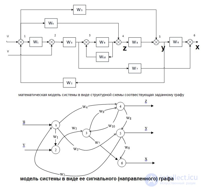
The structural scheme of the ACS is considered as one of the types of the signal flow graph. The directional (signal) graph of the ACS is constructed according to the equations written, like the block diagram of the ACS, in the accepted conditionally resolved form. 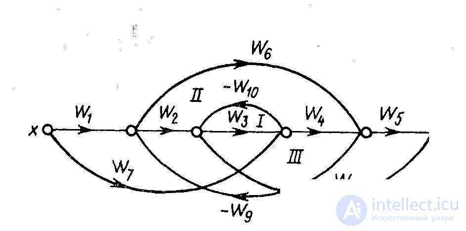
Table 1. Algebra W (p) . Correspondence of structural diagrams to graphs 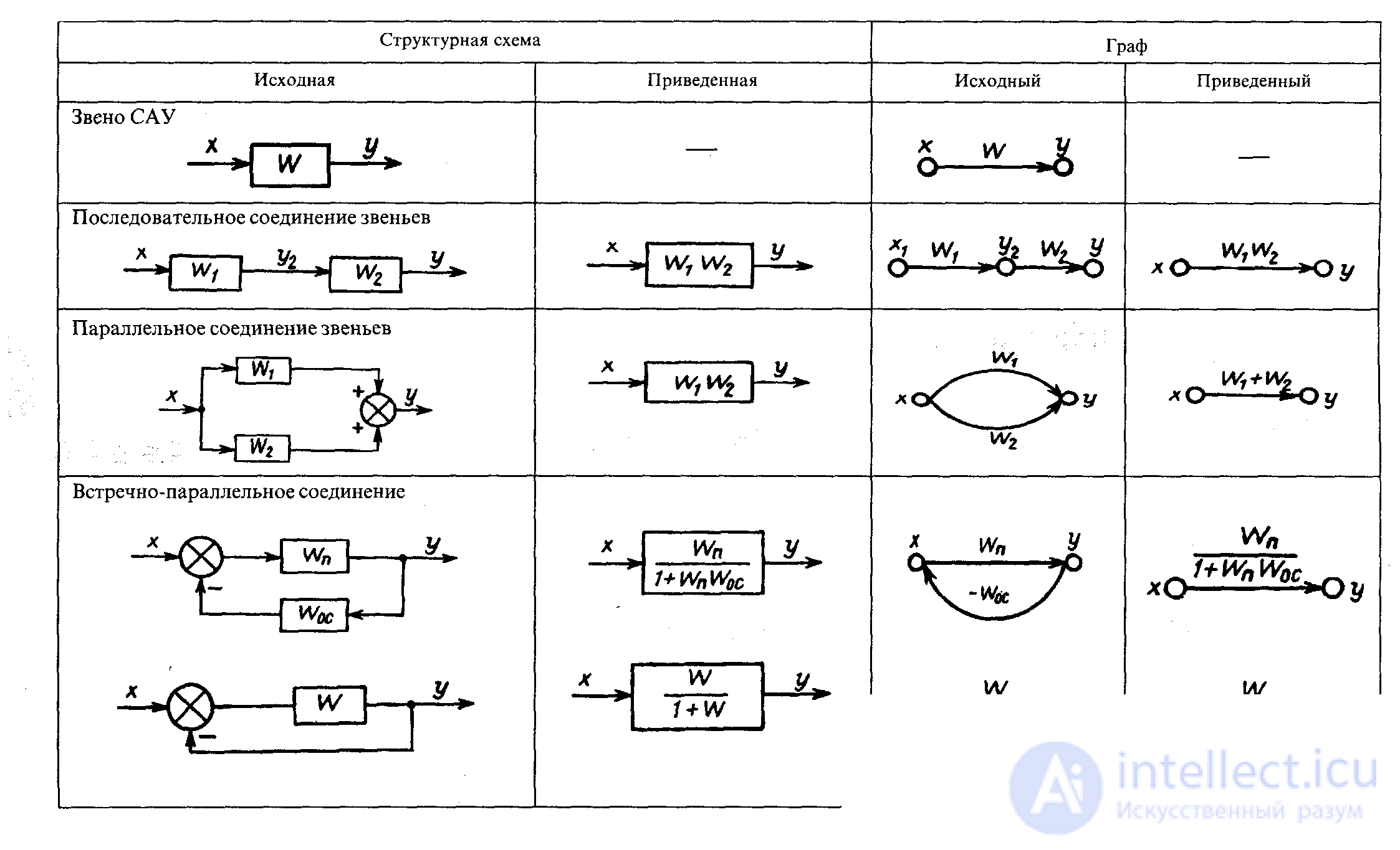
An example is a mathematical model of a system in the form of a structural diagram corresponding to a given graph
Task 1. Convert the original structural scheme, defining the transfer function of the system, provided  .
. 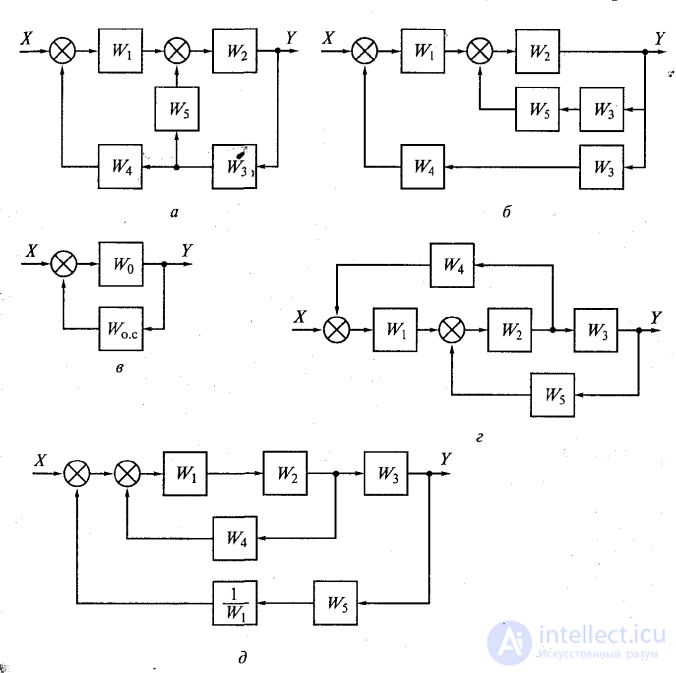
Fig.1a
Fig.1.b
Task 2. Transform block diagrams and determine the transfer function of the ACS. 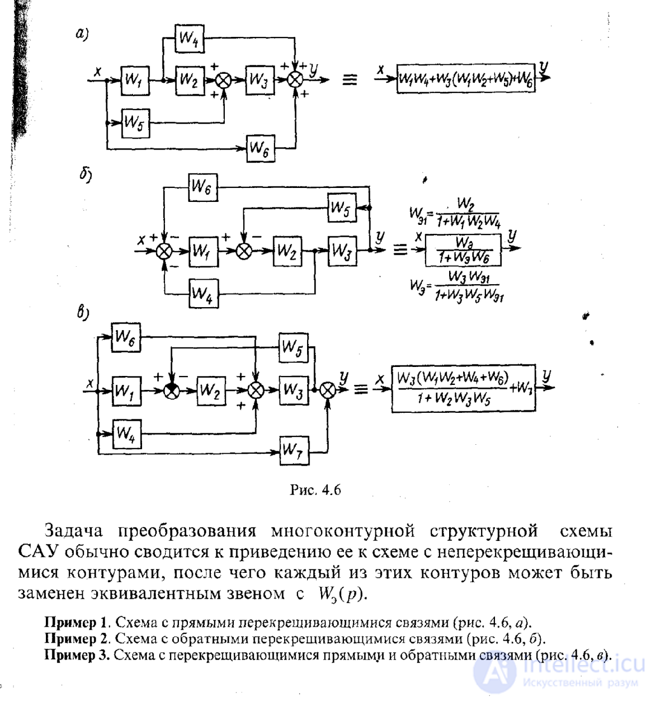
Figure 3
Example 1 Scheme with direct intersecting links (Fig. 3, a).
Example 2 Scheme with reverse cross links (Fig. 3, b).
Example 3 Scheme with overlapping direct and feedback (Fig. 3, c).
Task 3. Roll the pictured in fig. 4 block diagram of the ACS and determine the OFP of the closed-loop system using the main channel and the OFP error if W 1 (p) = 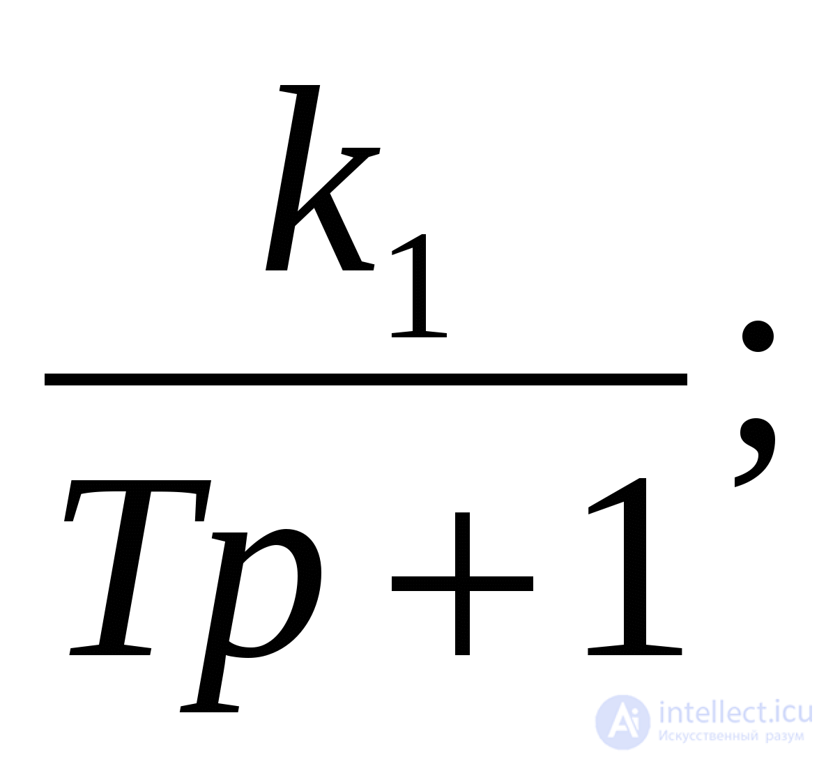 W 2 (p) =
 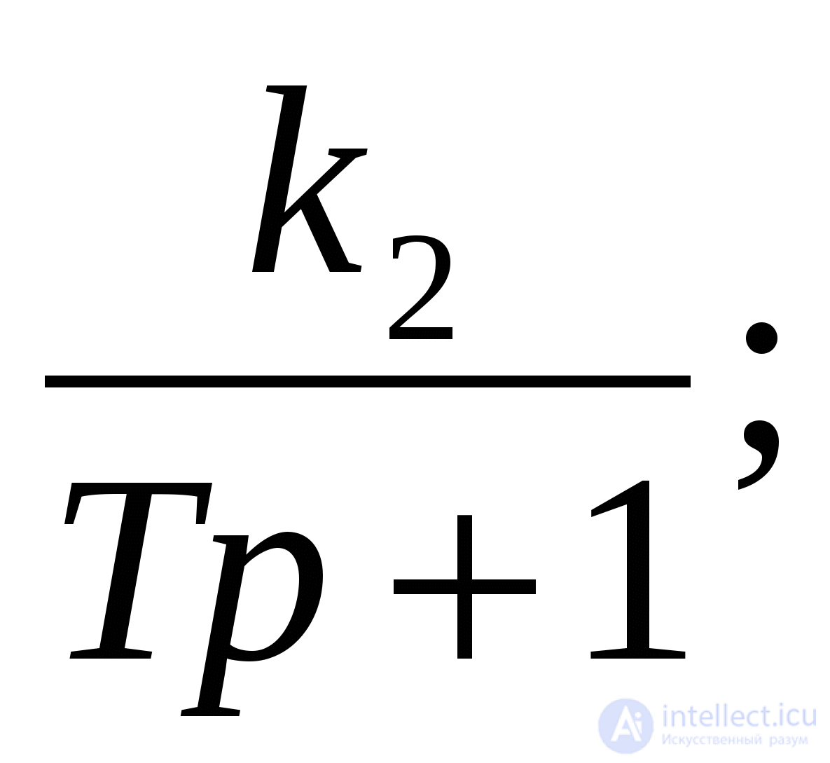 W 3 (p) =
 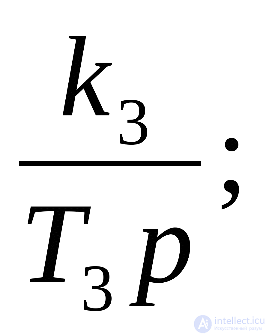 W 4 (p) =
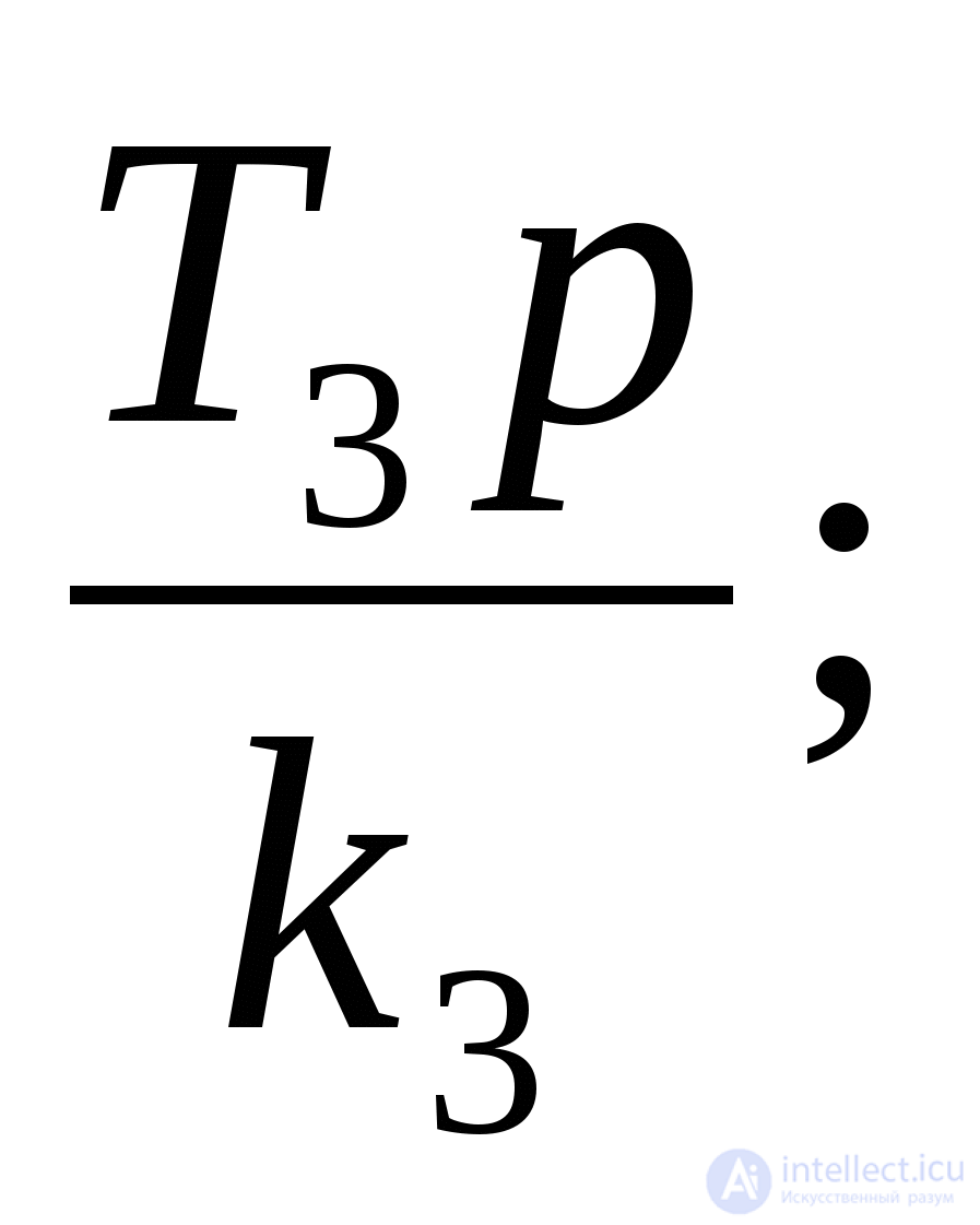
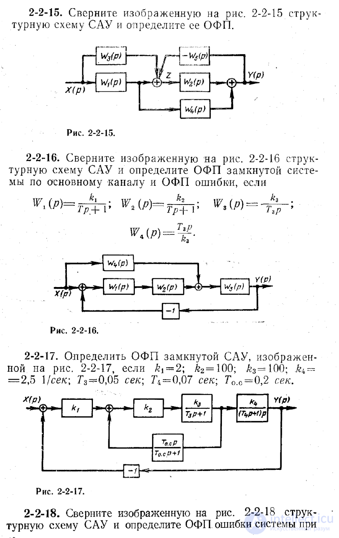
Figure 4
Task 4.
Transforming the block diagram (Fig. 5), get in general:
1) the transfer function of an open-loop system;
2) the transfer function of a closed system for a disturbing action;
3) the transfer function of the closed-loop system for the control action. 
Figure 5.
Task 5.
On the basis of the structural scheme (Fig. 6), to obtain in a general form the transfer functions of the system for the output quantity and error. 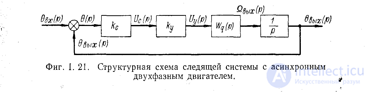
Figure 6
Task 6.
For a given transfer function, draw a block diagram of the system and a graph of the control system according to its block diagram. 
Task 7. On the basis of the structural scheme (Fig. 7), to obtain in a general form the transfer function of a closed system. System parameters: k with = 0.4 w / deg; T g = 0.06 seconds; T m = 0.1 sec .; With e = 0.014  ; j = 297; k y2 = 5.2, K y1 = 1.5 , k 0 = 3,2 .
Figure 7

Comments