Lecture
A block diagram is a conventional graphic representation of a mathematical model of an automatic system (hereinafter referred to as the AU).
The structural diagram consists of images of elementary dynamic links in the form of rectangles, in which their transfer functions and switching elements are recorded (Table 1.1). An example of the simplest structural scheme is shown in Fig. 1.1.
Table 1.1
Elements of structural schemes
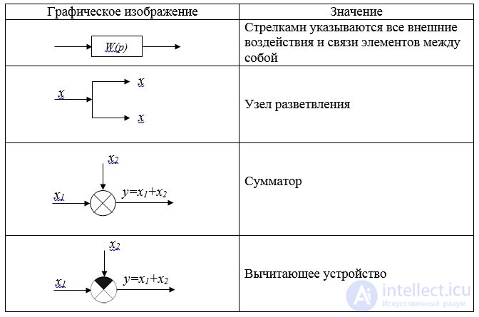

Fig. 1.1. The simplest structural diagram
The structural scheme differs from the functional one in that it gives a complete mathematical description of the system, but does not necessarily have to correspond to the very structure of the described system. The element of the structural scheme does not necessarily correspond to the real element of the automatic system.
Three basic types of compound elements.
1. When the elements are connected in series, the output signal of each preceding element is the input signal of the subsequent element (Fig. 1.2).

Fig. 1.2. Consistent connection of elements
The transfer function of the system:
 (1.26)
2. Parallel connection of links is called such a connection, in which the output of all elements receives the same effect, and their output values are algebraically summed (Fig. 1.3):
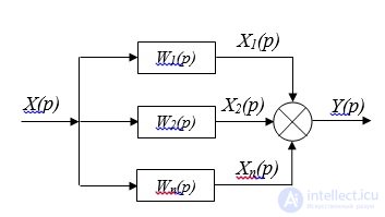
Fig. 1.3. Parallel connection of elements
The transfer function of the system:
 (1.27)
3. A counter-parallel connection of two elements is called such a connection, in which the output signal of the second element arrives at the output of the second, and the output signal of the second element is algebraically summed with the common input signal. Diagram of the anti-parallel connection is shown in Fig. 1.4:

Fig. 1.4. Counter-parallel connection
Negative feedback transfer function:
 (1.28)
Positive feedback transfer function:
 (1.29)
W p ( p ) is the transfer function of the open-loop system;
W oc ( p ) - feedback transfer function;
Example 1. Input and output signals are given:

a) find the transfer function W (p) of the entire system;
b) present the transfer function in the form of a product of elementary dynamic links;
c) find the system parameters.
Decision:
a) The transfer function of the entire system:
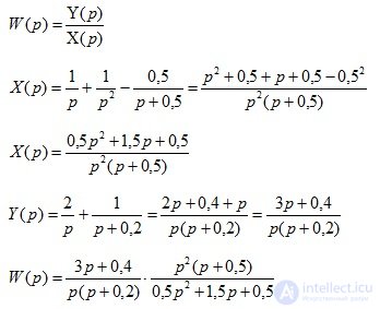
b) Transfer function in the form of a product of elementary dynamic links:

c) System parameters:
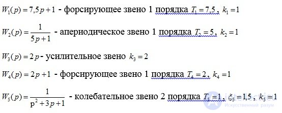
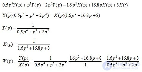
Example 2. The operator of a linear stationary system is given:

a) Determine the transfer function W (p) of the entire system;
b) present the transfer function of the system by sequential connection of links;
Decision:
1. The transfer function of the entire system:
2. The transfer function W ( p ) can be represented by a serial connection of elementary dynamic links:
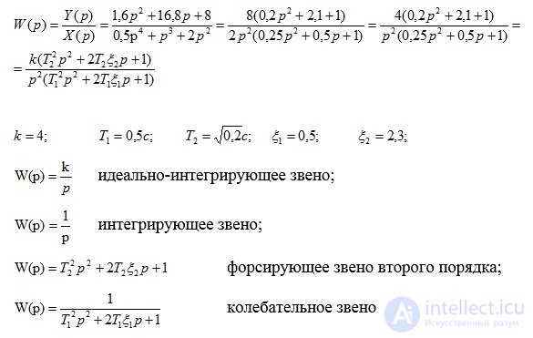
The structural scheme will look as follows (Fig. 1.5):

Comments
To leave a comment
Mathematical foundations of the theory of automatic control
Terms: Mathematical foundations of the theory of automatic control