Lecture
1.1.1. Processes and signals. Dynamic process or movement , is called the development in time of a physical phenomenon. The processes include the movement of mechanisms, thermal phenomena, economic processes, etc.
Processes spawn information flows, 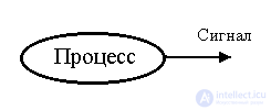 those. secondary processes that carry information about the primary dynamic process. A process containing information on the development of a physical phenomenon (primary process) is called a signal
When considering a signal, it is customary to distinguish between its information content (information about the primary process) and the physical nature of the corresponding secondary process (carrier). Depending on the physical nature of the carrier, acoustic, optical, electrical and electromagnetic signals can be distinguished. In general, the nature of the physical carrier does not coincide with the nature of the primary process.
Remark 1.1. Signals as well as their generating processes exist regardless of the presence of gauges or an observer.
In various fields of science and technology adopted their definitions and approaches to the study of signals. The cybernetic interpretation of this concept, considered here, provides for a refusal to study the physical features of both the primary process and the signal carrier. The signal is identified with information about changes in the physical variables of the process under study. This takes into account that, for various reasons, the real signal does not contain all the information about the development of a physical phenomenon, but, on the other hand, may contain extraneous information. The information content of the signals is influenced by their coding methods, noise, and quantization effects.
Depending on the encoding method distinguish between analog and digital signals. For analog signals, the intensity of the physical carrier is proportional to (similar to) the physical variable under study, while in digital signals information is presented in the form of numbers (for example, in the form of parallel and serial binary codes).
Methods of transformation, coding and transmission of information are specifically studied in applied information theory. In control theory, it is of interest how coded information is adequate to the physical variable under consideration. This question is related to the concepts of ideal and real signal.
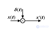
From the informational point of view, the ideal signal is identical to some physical variable x (t), while the real signal can be represented as
x ' ( t ) = x ( t ) +  ( t )
( t )
Where  (t) - measurement noise or noise, i.e. extraneous information about the communication channel, the external environment or the meter.
The concept of a real signal is associated with the identification (estimation) of dynamic processes from current measurements x ' ( t ) and in particular the following tasks:
 ( t ) the studied process x ( t );
  ( t-
( t-  ) where
  - lag interval;
  ( t + c
  ) .
) . The tasks of estimating the primary process from real measurements are considered in the theory of estimation (identification).
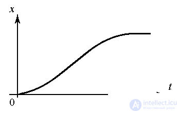
The information content of the signal depends on the effects of quantization. By the nature of the change over time, the processes and signals are divided into continuous and discrete. The latter, in turn, include processes quantized by level and processes quantized by time.
The development of a continuous unquantized process is characterized by the variable x (t), which takes arbitrary values from the numerical region X and is determined at any time points t > 0. Continuous processes include continuous mechanical motion, electrical and thermal processes.
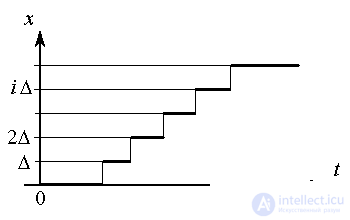
The development of a discrete ( level-quantized ) process is characterized by the variable x ( t ) , which takes strictly fixed values x i , i = 1,2 ..., and is defined at any time points t > 0. In most practical cases, we can assume
x i = i  x, i =
  ,
,
Where  x is the increment or level of discreteness, n is the number of admissible states.
The processes quantized by level include:
Remark 1.2. In cases where the number of states n is sufficiently large or the interval of discreteness  x is small enough, level quantization is neglected.
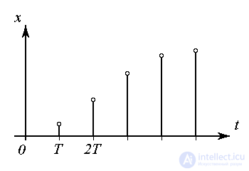
The development of a discrete ( time-quantized ) process, or a discrete time process, is characterized by the variable x (t ) taking arbitrary values of x and determined at fixed times t i , i = 0,1,2 ... In many cases
t = i T, i  0,
0,
where T is the quantization interval (discreteness). These processes include:
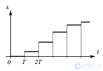
Remark 1.3. For sufficiently small (compared to the duration of other processes) intervals T , time discreteness is neglected and the time-quantized process is referred to as processes of continuous time.
Remark 1.4 . By discrete, usually also include piecewise-constant processes and signals, which are characterized by the variable x ( t ) , which jump-likely change at fixed points in time t i .

1.1.2. Cybernetic blocks. A cybernetic unit ("black box") is a unit for which the input and output signals are associated with a causal relationship. The output signal of the block x 2 ( t ) carries information about the internal process caused by the input signal x 1 ( t ) .
Remark 1.5. In the definition of a block, there is no mention of the physical nature of the processes inside the block, which is what the term “black box” has defined.
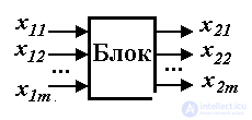
Depending on the number of input and output signals, single-channel blocks are distinguished, i.e. blocks with one input and one output, and multichannel with several input and output signals. Blocks that have no input signals are called autonomous . The type of signals distinguish between continuous , discrete and discrete-continuous blocks.
To describe the cybernetic block, one of the forms of the analytical description of the input and output signals is used. For the simplest blocks, such a description can be obtained in the form of an algebraic or transcendental equation:
(1.1) x 2 = f ( x 1 ) ,
where f (·) is a function. In the more general case, differential and difference (recurrent) equations, automaton algorithms, i.e. type expressions
(1.2) x 2 ( t ) = F ( x 1 ( t )) ,
where F (·) is a functional operator.
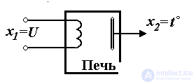
Fig. 1.1. Electric heating furnace
Example 1.1. Consider an electric heating furnace, i.e. chamber (Fig. 1.1), the temperature in which t o is controlled by an electric heater. The input signal of the block under consideration is the heater voltage: x 1 ( t ) = U ( t ), and the output is the temperature: x 2 ( t ) = t o ( t ) . The connection of the output and input is described by the functional operator (differential equation):
(1.3) 
where T is the time constant, K is the transfer coefficient. If the heater voltage is constant, i.e. x 1 = U = const , then the output variable is as
 .
.
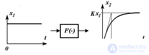
Fig. 1.2.
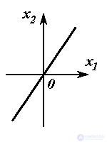
In the steady state, i.e. after the end of the processes in the furnace at  , the relationship between the output and input signals is described by the simplest algebraic equation of the form (1.1)
(1.4)  .
.
Similar expressions for describing the connections of input and output variables are obtained for an electric RC circuit (Fig. 1.3). Here x 1 (t) = U 1 (t) is the input voltage, x 2 (t) = U 2 (t) is the output voltage of the circuit, T = RC and K = 1 .
Finally, the same equations (1.1) and (1.2) describe the process of acceleration of an electric motor (Fig. 1.4), for which x 1 (t) = U (t) is the input voltage, and x 2 (t) =  (t) - the speed of rotation of the shaft.
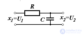
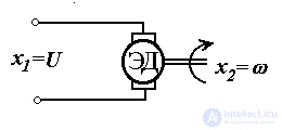
Fig. 1.3. RC - circuit 1.4. Electric motor
The following tasks are associated with the concept of a cybernetic unit:
1.1.3. Cybernetic systems. A cybernetic system is an ordered set of (system) cybernetic units interconnected by information channels.
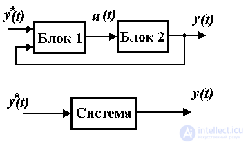
Remark 1.6. The concept of a system implies the emergence of a new quality, generally speaking, different from the properties of its individual elements. The links mentioned in the definition are of a signal (informational) nature.
To describe the system, it is necessary to obtain analytical dependencies describing each of the blocks (Block 1, Block 2, etc.) separately and the relations between them. After equivalent transformations, a general (equivalent) description of the system can be obtained as a composite cybernetic unit with an input signal y * ( t ) and an output signal y ( t ). (see paragraphs 2.4 and 4.3)
Thus, the cybernetic system is a complex block. Depending on the number of input and output signals, there are single-channel systems (with one input and one output), and multi-channel systems with several input and output signals. Systems that have no input signals are called autonomous .
According to the type of signals in the system (or blocks), there are distinguished: continuous, discrete and discrete-continuous systems , the latter containing both continuous and discrete blocks (see below).
The definition of a cybernetic system allows you to enter the following tasks:
The applied task of designing a system is also known, which includes the task of controlling (synthesis of the system), its configuration (selection of physical elements), development of application programs for control computers, etc.
The most common type of discrete-continuous systems are digital systems, which include digital computing devices (computers and digital controllers).
1.1.4. Discrete continuous (digital) systems. Consider the simplest digital control system of the rotation of the kinematic mechanism (Fig. 1.5). The system includes the simplest kinematic mechanism KM, electric motor ED, amplifier U, digital-analog converter D / A converter and computer control computer.

Fig. 1.5. Control system of rotation of the kinematic mechanism
The system works as follows. Information about the required angle of rotation (task)  * arrives at the computer, where the required control signal N u ( t ) is calculated. The latter is represented as a digital code that is converted to an analog control signal u ( t ) using a digital-to-analog converter. Since the received signal power u ( t ) is not enough to drive an electric motor, a power amplifier U is required to be connected. The output voltage of the amplifier U ( t ), when applied to the motor, creates the necessary driving moment (signal M ( t )) . The moment of the electric motor is applied to the shaft of the kinematic mechanism and ensures its rotation, i.e. change in angular position
  ( t ) from the initial value
  (0) to the set value
  * .
* .
Note that the signals in the considered system are different in physical nature and methods of coding. Due to the discreteness of processes in digital computing devices and the finiteness of their bit grid, a computer belongs to discrete blocks, and the signal at its output N u ( t ) is quantized in time and level.
The system shown in Fig. 1.5, belongs to the class of open control systems, in which the control problem (changing the state of the CM) is solved without taking into account the real position of the mechanism  ( t ). This causes, firstly, certain difficulties in calculating the control signal u ( t ) providing the specified angular displacement of the mechanism
  * and, secondly, it does not allow to guarantee sufficient control accuracy under the conditions of action on the mechanism of forces of gravity and friction. These deficiencies are eliminated in closed systems, which include the monitoring subsystem and feedback.
Let us supplement the system considered earlier with the following elements (Fig. 1.6): a measuring potentiometer, the output voltage of which is u  ( t ) proportional to current value
  ( t ), amplifier U and analog-to-digital converter ADC, which performs the conversion of the signal U
  ( t ) at the output of the amplifier in digital code N
  ( t ), coming further to the computer. These elements, in conjunction with a computer, constitute a digital subsystem for controlling the rotation of the kinematic mechanism, providing measurement of the current position of the CM and input of information into the control computer.
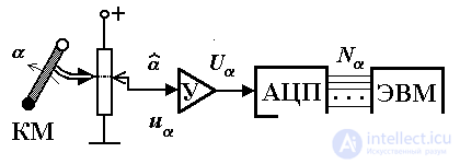
Fig. 1.6. Control subsystem
Note the discrete nature of the signal (digital code) N  ( t ), due to the functional features of the ADC, and, therefore, the discrete-continuous type of the considered control subsystem.
Combining an open control system (Fig. 1.5) and a control subsystem (Fig. 1.6) allows you to get a closed control system. The enlarged diagram of such a system is presented in Fig. 1.7. It includes a digital control unit and an electro-mechanical unit (EM unit). Последний включает аналоговые элементы системы (кинематический механизм, двигатель, усилители и измерительный потенциометр) и по типу сигналов относится к непрерывным блокам. В блок управления входит ЭВМ и устройства ввода-вывода информации (УВВ), или сопряжения с объектом (УСО), представленные цифро-аналоговыми и аналого-цифровыми преобразователями и обеспечивающие сопряжение цифровой и аналоговой частей системы управления.

Fig. 1.7. Замкнутая система управления
В функции цифрового блока управления входит расчет управляющего сигнала u ( t ) на основании задания  * и текущей информации о положении кинематического механизма
  ( t ). Простейший алгоритм расчета (пропорциональный алгоритм управления) имеет вид
(1.5) u ( t ) = K (  * -
* -  ( t )),
where K is a constant factor. In calculations using formula (1.5), the control signal is proportional to the current deviation value  * -
* -  ( t >), which ensures:
 t )
t ) 
 * ;
* ; * =
* =  ( t ) в силу u ( t ) = 0 и, следовательно, нулевых значений напряжения на выходе усилителя мощности U вращающего момента М .
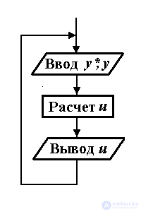
Укрупненный алгоритм работы ЭВМ в режиме реального времени представлен на рис. 1.8. Он включает блок ввода данных (задания у* =  * и текущего значения у =
  )), блок расчета текущего значения управления u по формуле (1.5) и блок вывода данных (полученного значения u ). Циклическое выполнение алгоритма обеспечивает возможность обновления выходных данных в процессе работы системы при изменения входных данных (текущего значения
  ).
).
Циклический характер выполнения программы служит причиной временной дискретности сигналов N  и N u и цифрового устройства управления в целом. При этом интервал квантования приближенно оценивается временем, необходимым для выполнения одного цикла программы.
Отметим, что рассмотренная система управления является составным кибернетическим блоком с входным сигналом у* =  * и выходным сигналом y=
  ( t ). Система содержит обратную связь по выходной переменной (сигнал у поступает обратно на вход системы). Ее аналитическое описание (связь у* и y ) можно получить на основании известных приемов преобразования динамических систем (см. пп. 2.4 и 4.3), используя описание электромеханического блока (связь сигналов y и u ) и формулу (1.5).
1.1.5. Кибернетика и предмет теории автоматического управления. Понятие кибернетики как науки об управлении и связи в живом (природе и обществе) и машинах было введено в 1948 году Норбертом Винером. В настоящее время в виде отдельных дисциплин можно выделить следующие разделы кибернетики:
В зависимости от области применения различают техническую кибернетику, т.е. кибернетику в технических приложениях, биокибернетику, медицинскую кибернетику, экономическую кибернетику и др.
Теория автоматического управления (ТАУ) - наука об управлении, изучающая задачи анализа и синтеза систем автоматического управления (САУ), как одного из классов кибернетических систем. Основные разделы ТАУ - это:
Современная теория управления занимает одно из ведущих мест в технических науках и, в то же время, относится к одной из отраслей прикладной математики. Теория и практика автоматического управления связана с вычислительной техникой. В этой связи следует отметить, что исследование САУ включает следующие важнейшие этапы:
Первый проект по практической реализации цифровых систем был выдвинут в 1950 году американскими фирмами ТRW и Texaсo. В данном проекте ЭВМ использовалась как средство автоматизации химических процессов. Было установлено, что для успешной реализации цифрового управления требуется
Эти выводы определили в 60-ые годы интенсивное развитие математических методов управления, ориентированных на использованием ЭВМ. Однако их практическая реализация натолкнулась на ряд препятствий, среди которых низкое быстродействие существовавших средств вычислительной техники, их значительные габариты и стоимость, а также низкая надежность.
Решение проблемы было предложено в середине 70-ых годов с появлением серийных и достаточно дешевых микропроцессоров и микро-ЭВМ, которые могли обеспечить требуемое быстродействие управления, имели малые габариты и высокую надежность. Микропроцессорные устройства начинают постепенно вытеснять традиционные электрические и электронные средства управления (регуляторы) в простейших автоматических системах. Более того с развитием микропроцессорной техники появилась возможность реализации более
сложных алгоритмов для решения нетрадиционных задач управления.
Проектирование, внедрение и эксплуатация современных САУ требует взаимодействия специалистов различных профилей:
Comments
To leave a comment
Mathematical foundations of the theory of automatic control
Terms: Mathematical foundations of the theory of automatic control