Lecture
STABILIZER
1. What is the relative change in voltage at the output of the parametric stabilizer, if the current of the Zener diode has changed by 2 mA, Ust = 8 V, Rdif = 16 Ohm?
Decision:

2. Voltage u = Um (1.5 - 2t / T) B is supplied to a chain of series-connected resistors R = 200 Ohm and Zener diode КС182. Determine the current in the circuit for t = 0.2T, if the differential resistance of the Zener diode Rн = 30 Ohm, Um = 12 V.

Decision:
i = (u - Ust) / (R + Rn)
U (0,2T) = 1,1Um
i (0,2T) = (14 - 8,2) / 230 = 0,025 A
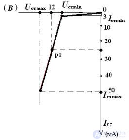
3. Draw a characteristic of the Zener diode with the parameters:
Ust = 12 V, Ist min = 3 mA, Rdif = 25 Ohm
Is max max = 50 mA.
Decision:
∆Ist = Ist max - Ist min = 50 - 3 = 47 mA
∆ Ust = ∆Ist • Rdif = 0.047 • 25 = 1.175 V
Ust min = Ust - Δ Ust / 2 = 11.42 V
Ust max = Ust + ∆ Ust / 2 = 12.59 V
We build the current-voltage characteristics of the Zener diode as shown in the figure.
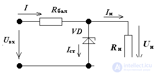
4. For the stabilizer circuit, the zener diode has the parameters:
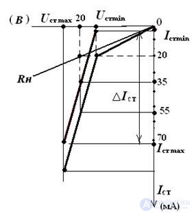
Ust = 20 V, Ist min = 1 mA, Rdif = 40 Ohm, Ist max = 71 mA. Determine the current I in the circuit in a graphical way, if In = 20 mA:
Decision:
I = Ist + In
∆Ist = Ist max - Ist min = 71 - 1 = 70 mA
∆ Ust = ∆Ist • Rdif = 0.07 • 40 = 2.8 V
Ust min = Ust - ∆Ust / 2 = 18.6 V
Ust max = Ust + ∆Ust / 2 = 21.4 V
We build the current-voltage characteristics of the zener diode, the voltage-current characteristics of the resistor. We summarize the CVC-ki. Graphically determine the current unbranched part of the circuit.
I = 55 mA
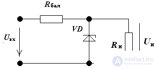
5. To stabilize the voltage in the load Rn = 2 kΩ, a parametric voltage regulator is used. Zener diode has parameters:
Ismin = 1 mA, Ismamax = 23 mA, Rdif = 30 Ohm; the rated output voltage is 11 V, the input voltage is 22 V.
Define Kst and Rbal.
Decision:
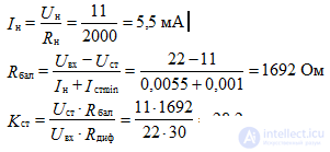
6. Determine the voltage at the input of the stabilizer. Options
Zener diode: Ust = 12 V, Ist min = 5 mA, Ist max = 35 mA, Rdif = 20 Ohm
Rbal = 800 Ohm, Rn = ∞.
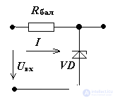
Decision:
current through the stabilizer

Since the zener diode and the ballast are connected in series in a circuit,

According to the second law Kirchhoff:

7. Determine U2 in the voltage regulator, if U1 = 16 V, R1 = 300 Ohm,
R2 = 1.2 kΩ, Umin min = 12 V, Rst = 15 Ohms.
Note: solve the problem by an analytical method, using a Zener diode equivalent circuit (source emf E = Ust, connected in series with the resistor Rst).
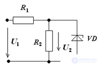
Decision:
Draw the equivalent circuit stabilizer
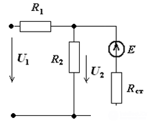
We use the method of two nodes:

U2 = 12.2 V
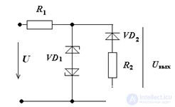
8. Periodic voltage u varies according to the law u (t) = 24 (1 - 2t / T), where T is the period. Voltage stabilization of the Zener diode 8 V. R1 = R2 = 1 kΩ.
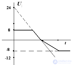
Build a graph of voltage at the output.
Diode and Zener diode considered ideal.
Decision:
In the positive half-period, the diode VD2 is closed. The voltage Uout at t = 0 will be equal to the stabilization voltage. From the moment of time
t = T / 3 to T / 2 varies from 8 V to zero.
In the negative half-period, the diode VD2 is open. When the branch with zener diodes is disconnected, the voltage across resistor R2 varies from zero (at t = T / 2) to –12 V, at t = T. Connecting the branch with zener diodes limits the output voltage to –8 V.
Comments
To leave a comment
Electronics, Microelectronics, Element Base
Terms: Electronics, Microelectronics, Element Base