Lecture
Full-wave rectifier
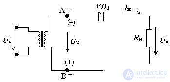
It is considered that the transformer and the rectifying diode are ideal, that is, the transformer has a winding resistance of zero, a diode Rpr = 0 and Rbr = ∞.

Fig.2 Diagram of half-wave rectifier
Rectifier operation principle
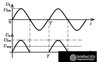
Consider the time diagrams of a half-wave rectifier (Fig. 3) in the time interval 0 - T / 2, the diode VD1 is open φА> φВ, a current in is in the load.
In the time interval T / 2 - T, the diode is closed φА <φВ, U2m is applied to the diode.

Fig.3. Half-Wave Rectifier Timing Diagrams
The current and voltage in the load are pulsating and, as a result, differ significantly from the constant components
The main electrical parameters of the rectifier
The diode in the rectifier is the main element and in many respects determines the main indicators of the rectifier.
1. Unsr and Insr - the average values of the rectified voltage and current in the load device
2. Power load device Pnsr = Unsr • Insr
3. Amplitude of the main harmonic
4. The ripple coefficient of the rectified voltage

5. Efficiency rectifier
6. Reverse maximum voltage on the locked diode Uobrmax
Determine the average value of the rectified voltage and current in the load.
In a half-wave rectifier, more than half of the input voltage is lost!

Input voltage (voltage on the secondary winding of the transformer):

The average value of the rectified current, the average rectified current is equal to the current through the diode:

The ripple frequency of the rectified voltage is equal to the frequency of the mains voltage:
fп = fbas
The rectified voltage has a non-sinusoidal waveform, so it can be decomposed into a Fourier series:

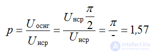
Since the frequency of the ripples of the rectified voltage is equal to the frequency of the network, then when calculating the ripple coefficient, the voltage of the main first harmonic is taken:

p = 1.57 - a very large ripple factor - this is a drawback of the circuit.
The reverse maximum voltage on a locked diode is equal to the amplitude of the input voltage:

When choosing a rectifier diode, the maximum permissible parameters are used: the direct current is the maximum allowed and the reverse voltage is the maximum allowed: Iprmax, Uobrmax.
Diode in rectifiers is the main element, and its parameters largely determine the main parameters of rectifiers
Comments
To leave a comment
Electronics, Microelectronics, Element Base
Terms: Electronics, Microelectronics, Element Base