Lecture
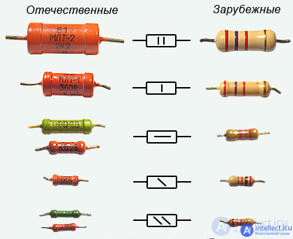
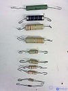
resistors of different ratings and accuracy, marked with a color scheme
Resistor(Engl. Resistor , lat. Resisto - resist) - an electrical circuit element for use egoelektricheskogo resistance. [1]
In addition to electrical resistance, resistors are also characterized by parasitic capacitance, parasitic inductance and non-linearity of the current-voltage characteristic.
The resistor is a passive single-port element.
where is an arbitrary function of two variables.
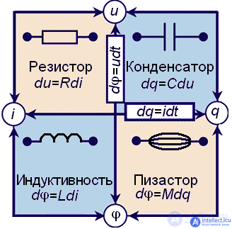

a) designation adopted in Russia and Europe
b) adopted in the USA
The old designation of the resistor in the diagrams
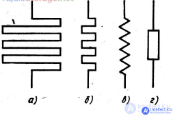
Initially, the resistors were depicted on the diagrams as a broken line - a meander (Fig. 1, a, b), which denoted a high-resistance wire wound on an insulating frame. As the radio devices became more complicated, the number of resistors in them increased, and, in order to facilitate the mark, they decided to depict them on the diagrams in the form of a gear line (Fig. 1, c).
This symbol was replaced by a symbol in the form of a rectangle (Fig. 1, d), which they began to use to designate any resistor, regardless of its design and features.
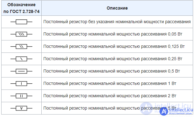
In Russia, the graphic symbols for resistors in the diagrams must comply with GOST 2.728-74. In accordance with it, fixed resistors are indicated as follows:
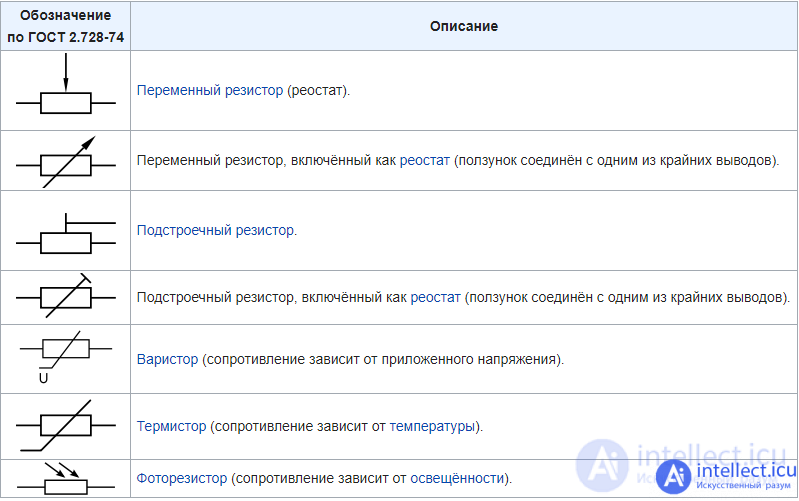
Variable, tuning and non-linear resistors are indicated as follows:
When the resistors are connected in series, their resistance


Proof [show]
If  , then the total resistance is:
When the resistors are connected in series, their total resistance will be greater than the largest of the resistances.
When the resistors are connected in parallel, the reciprocal of the resistance is  added (that is, the total conductivity is the sum of the conductivities of each resistor
  )
)
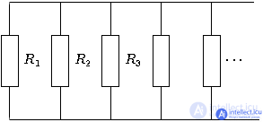

If the circuit can be divided into nested subunits that are connected in series or parallel with each other, then first consider the resistance of each subunit, then replace each subunit with its equivalent resistance, thus finding the total (desired) resistance.
Proof [show]
For the two parallel-connected resistors their total resistance is:  .
.
If  , then the total resistance is:
When the resistors are connected in parallel, their total resistance will be less than the smallest of the resistances.

The circuit consists of two parallel-connected blocks, one of them consists of series-connected resistors  and
and  , with a common resistance
  , the other of a resistor
  , the total conductivity will be equal
  , that is, the total resistance
  .
.
To calculate such circuits of resistors that cannot be divided into blocks in series or in parallel connected to each other, the Kirchhoff rules are applied. Sometimes, to simplify the calculations, it is useful to use the triangle-star transformation and apply the principles of symmetry.
As with parallel and serial connection of resistors, the total power will be equal to the sum of the connected resistors.

Voltage divider
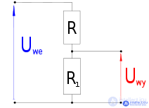
Voltage divider.

If R = 9R1, then UWY = 0.1UWE, that is, the input voltage will be divided by 10 times.

Three SMD resistors soldered onto a printed circuit board.
Resistors are elements of electronic equipment and can be used as discrete components or as integral parts of integrated circuits. Discrete resistors are classified by purpose, type of I – V characteristic, by the method of protection and by the method of installation, the nature of the change in resistance, manufacturing technology. [3]
By appointment:
By the nature of the change in resistance:
Fixed resistors (for surface mounting). |
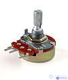
Variable resistor. |

Trimmer Resistors. |

Precision multi-turn trimming resistor. |
By protection method:
By installation method:
By the type of current-voltage characteristics:
By manufacturing technology [ :
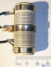 Branch Wirewound Resistor
 Film carbon resistor (part of the protective coating removed to demonstrate the conductive layer).
| . |
Resistors
Resistors of the same rating manufactured by industry have a range of resistances. The value of the possible spread is determined by the accuracy of the resistor. Resistors are manufactured with an accuracy of 20%, 10%, 5%, etc. up to 0.01% [4]. The values of the resistors are not arbitrary: their values are selected from special nominal series, most often the isominal series E6 (20%), E12 (10%) or E24 (for resistors with an accuracy of 5%), for more accurate resistors, more accurate series are used (for example E48).
Resistors manufactured by the industry are also characterized by a certain value of maximum power dissipation (resistors with a capacity of 0.125W 0.25W 0.5W 1W 2W 5W are manufactured) (According to GOST 24013-80 and GOST 10318-80, the Soviet radio industry produced resistors of the following power ratings, in Watts, Tue: 0.01, 0.025, 0.05, 0.062, 0.125, 0.5, 1, 2, 3, 4, 5, 8, 10, 16, 25, 40, 63, 100, 160, 250, 500)
[5]
Resistors, especially low power - small parts, a 0.125W resistor has a length of several millimeters and a diameter of the order of a millimeter. It is difficult to read a denomination with a decimal point on such a part, therefore, when specifying the denomination, instead of the decimal point, write the letter corresponding to the units of measurement (K for kilo ohms, M for megaohms, E or R for units of Ohms). In addition, any value is displayed with a maximum of three characters. For example, 4K7 denotes a resistor with a resistance of 4.7 kOhm, 1R0 - 1 Ohm, M12 - 120 kOhm (0.12 MΩ), etc. However, it is difficult to apply values to small resistors in this form, and they are marked with color bars.
For resistors with an accuracy of 20%, markings with three strips are used, for resistors with an accuracy of 10% and 5% markings with four strips, for more accurate resistors with five or six strips. The first two stripes always mean the first two digits. If the strips are 3 or 4, the third stripe means the decimal factor, that is, the power of the tens, which is multiplied by the two-digit number indicated by the first two strips. If strip 4, the latter indicates the accuracy of the resistor. If stripes 5, the third means the third sign of resistance, the fourth means the decimal factor, and the fifth means accuracy. The sixth bar, if any, indicates the temperature coefficient of resistance (TCR). If this strip is 1.5 times wider than the rest, then it indicates the reliability of the resistor (% failure per 1000 hours of operation)
It should be noted that sometimes there are resistors with 5 bands, but standard (5 or 10%) accuracy. In this case, the first two bands specify the first signs of the face value, the third - the factor, the fourth - the accuracy, and the fifth - the temperature coefficient.
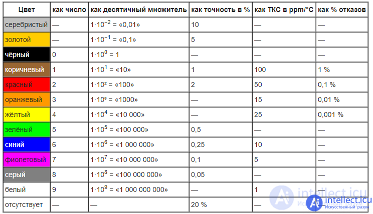
Example
Suppose there are four bands on a resistor: brown, black, red and gold. The first two strips give 1 0, the third 100, the fourth gives an accuracy of 5%, total resistor 10 · 100 Ohm = 1 kOhm, with an accuracy of ± 5%.
It is not difficult to remember the color coding of resistors: after black 0 and brown 1, there is a sequence of rainbow colors. Since the marking was invented in English-speaking countries, cyan and blue do not differ.
Also, to facilitate memorization, you can use the mnemonic rule: "Often Every Red Hunter Wants to Know How Many Pheasants Village in the Swamp."
To facilitate this, various software developers create programs that determine the resistance of a resistor.
Since the resistor is a symmetrical part, the question may arise: “From which side should the strips be read?” For four-band marking of conventional resistors with an accuracy of 5 and 10%, the question is solved simply: a gold or silver strip always stands at the end. For a three-strip code, the first strip is closer to the edge of the resistor than the last. For other options, it is important that the resistance value is obtained from the nominal series, if it does not work, you need to read the opposite. (For MLT-0.125 resistors manufactured by the USSR with 4 strips, the first is a strip deposited closer to the edge; usually it is on a metal output cup, and the other three are on a narrower ceramic body of the resistor). In Panasonic five-band resistors, the resistor is positioned so that the freestanding strip is on the right,the first 2 stripes - determine the first two characters, the third strip - the degree of the multiplier, the fourth strip - tolerance, the fifth strip - the scope of the resistor. A special case of using color marking of resistors is jumpers of zero resistance. They are indicated by a single black (0) stripe in the center. (The use of such resistor-like jumpers instead of cheap pieces of wire is explained by the desire of manufacturers to reduce the cost of reconfiguring assembly machines).(The use of such resistor-like jumpers instead of cheap pieces of wire is explained by the desire of manufacturers to reduce the cost of reconfiguring assembly machines).(The use of such resistor-like jumpers instead of cheap pieces of wire is explained by the desire of manufacturers to reduce the cost of reconfiguring assembly machines).
“Resistors” of zero resistance (jumpers on the board) are encoded with one digit “0”. More characters indicate:
3 or 4 digit coding
for example 102 is 10 • 10² Ohm = 1 kOhm
for example 1002 is 100 • 10² Ohm = 10 kOhm
1kΩ = 1000ohm
Letter-to-Digit Encoding (JIS-C-5201)
E96 series, 1% accuracy.
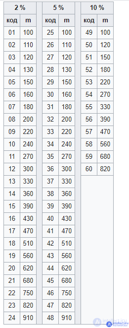
Mantissa m resistance values are encoded in 2 digits (see table), degree at 10 is encoded by a letter.
Examples: 09R = 12.1 ohms; 80E = 6.65 MΩ; all 1%.
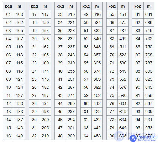
Letter-to-Number Encoding
Series E24 and E12, accuracy 2%, 5% and 10%. (E48 series is not used).
The degree at 10 is encoded by the letter (the same as for 1% resistances, see the list above), the mantissa is the resistance value and the accuracy is encoded by 2 digits (see table).
Examples:
Thermistor

Laboratory resistor
The resistance of metal and wire resistors is slightly dependent on temperature. In this case, the temperature dependence is almost linear  , since the coefficients of 2 and 4 orders of magnitude are quite small and can be neglected in ordinary measurements. The coefficient
  is called the temperature coefficient of resistance. This temperature dependence of the resistance allows the use of resistors as thermometers. The resistance of semiconductor resistors can depend more strongly on temperature, perhaps even exponentially according to the Arrhenius law, but in the practical temperature range this exponential dependence can also be replaced by a linear one.
Even an ideal resistor at temperatures above absolute zero is a source of noise. This follows from the fundamental fluctuation-dissipation theorem (as applied to electric circuits, this statement is also known as the Nyquist theorem). At a frequency substantially lower than  (where is the
  Boltzmann constant,
  is the absolute temperature of the resistor in degrees Kelvin,
  is Planck's constant), the thermal noise spectrum is uniform (“white noise”), the noise spectral density (Fourier transform from the noise voltage correlator)
  , where
  . It can be seen that the greater the resistance, the greater the effective noise voltage; also, the effective noise voltage is proportional to the root of the temperature.
Even with an absolute zero temperature, the resistors made up of quantum point contacts will have noise due to Fermi statistics. We eliminate by sequential and parallel connection of several contacts.
The noise level of real resistors is higher. In the noise of real resistors, there is also always a component whose intensity is proportional to the inverse frequency, that is, 1 / f noise or “pink noise”. This noise arises due to many reasons, one of the main recharging of impurity ions, on which electrons are localized.
The noise of resistors occurs due to the passage of current in them. In the variable resistors there are so-called "mechanical" noises arising from the operation of the moving contacts.
есть еще безиндукционные резисторы и
резисторы с нулевым сопротивлением
Comments
To leave a comment
Electronics, Microelectronics, Element Base
Terms: Electronics, Microelectronics, Element Base