Lecture
Differential Amplifiers
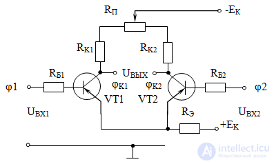
Designed to enhance the potential difference (voltage, current) supplied to the two inputs. The simplest circuit of an amplifier of this type is shown in Fig. 3

Fig. 3 Scheme of a symmetric differential amplifier with two bipolar transistors
The symmetric differential amplifier, whose circuit is shown in Fig. 3, consists of two parallel single-stage DC amplifiers connected in relation to the power supply. The input voltages (potentials) with respect to the common output (connected emitters) are fed to the corresponding basic outputs, and the output voltage, as the potential difference relative to the same common output, is removed from the collector outputs of the transistors.
If a  . The same result will be if the voltages at both inputs are the same in absolute value and have the same signs, i.e. when

If the input voltage does not match the sign or the absolute value, then the output voltage appears equal to the difference between the amplified voltages at the collector VT1 and VT2. In this way

where K is the shoulder gain; in parentheses - the algebraic sum of the voltages at the input, taking into account the sign of the potential: with a negative potential at the input, the sign of the input voltage is reversed.
It is necessary to take into account that in such an amplifier there is no common point between the signal source and the load: the output voltage is removed from the load resistance, which is connected to both collectors and is measured as the potential difference between them.
The resistance RE has a relatively large value, creating a current source mode in the emitter circuit of both transistors. In this case, in accordance with the first Kirchhoff law, there is no current increment in the emitter circuit when the currents in the arms of the differential amplifier change. The emitter circuit serves to stabilize the quiescent mode and in the differential stage does not affect the gain: there is no feedback on alternating current.
Since the differential cascade amplifies the potential difference, when the common-mode voltages (voltages of the same polarity, phase and amplitude) arrive at its inputs, the voltage at the output will be zero. For example, the electromagnetic field of the mains voltage may induce at the inputs of a differential amplifier an emf of the same sign and value that will not be transmitted to the output due to mutual compensation at the output. In a single-stage voltage amplifier, this effect is absent, since in it the voltage at the collector output of one transistor is measured with respect to the same common point as at the input.
The quality of the common mode attenuation is characterized by the common mode attenuation coefficient having the decibel dimension (dB). 
With high cascade symmetry, the common mode attenuation factor is

Comments
To leave a comment
Electronics, Microelectronics, Element Base
Terms: Electronics, Microelectronics, Element Base