You get a bonus - 1 coin for daily activity. Now you have 1 coin

tasks and examples DIODES, RECTIFIERS

Lecture


Solving electronics problems involving diodes and rectifiers requires an understanding of the basic principles of diode operation and the features of rectifier circuits. Here is a general step-by-step approach to solving such problems:

Understand diode properties: Study the basic properties of diodes such as the direction of current flow, switching voltage, and forward and reverse saturation current. This will help you determine how the diode behaves under various conditions.

Analyze the circuit: Consider a given circuit with diodes and determine their mode of operation. When working with rectifiers, also consider the type of rectifier (half-wave, full-wave, etc.).

Use diode equations: Use diode equations such as the Shockley-Reed equation to determine the current through and voltage across the diodes.

Calculate characteristics: Calculate the characteristics of the circuit such as the current and voltage across each element, power, efficiency, etc.

Check and interpret the results: Check the obtained values ​​for compliance with physical limitations and applicability. Interpret the results in light of the problem objectives and the circuit component specifications.

Account for Imperfections: Consider possible component imperfections such as diode voltage drops, wire resistance, etc.

Practice: Solve different types of diode and rectifier problems to improve your skills and understanding.

It is important to understand that electronics with diodes and rectifiers can be complex and solving problems requires an understanding of the basic principles and circuit analysis skills. Regular practice and study will help improve your skills in this area. If you have any difficulties, seek help from experienced professionals or teachers.


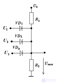
1. Given: circuit (Fig. 1), U1 = 10 B, U2 = 13 B, U3 = 15 В, U4 = 22 B, R1 = R2 =1 кОм.

Determine Uout
tasks and examples DIODES, RECTIFIERS


Solution:

When U1 = U2 = U3 = 0, the diodes are closed and the voltage
Uout = U4•R2 / (R1 + R2) = 11 V.
If we connect U1, Uout will not change - the diodes are closed.
When U2 is connected, the voltage Uout will be equal to 13 V (the diode in the branch with U2 will be open).
When U3 is connected, the diode in this branch will open, the voltage Uout will be equal to 15 V. The remaining diodes will be closed.


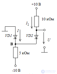
2. Considering the diodes to be ideal, find the current and voltage for the circuits shown in the diagram.
tasks and examples DIODES, RECTIFIERS

Solution:

For the circuit in the diagram, it is not obvious whether both diodes are in the conducting state. In this case, we will make an assumption about the diodes being in the conducting state, perform calculations and check the correctness of our assumption.
For the circuit in the diagram, from the assumption about the conductivity of both diodes, it follows that
UB = 0; U = 0
The current through the diode VD2 can be determined from the expression
tasks and examples DIODES, RECTIFIERS
Writing the equation for the currents in node B, we have
tasks and examples DIODES, RECTIFIERS
Thus, the diode VD1 is in the conducting state, as we initially assumed, and the final results
I = 1 mA and U = 0 V.


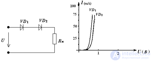
3. etermine the current in the circuit and the voltage on the diodes, the current-voltage characteristics of which are presented if Uin = 2.5 V, Rn = 25 Ohm
tasks and examples DIODES, RECTIFIERS


Solution:
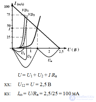
we will construct the total I-V characteristic of the diodes and the "inverted" VA characteristic of a load resistor.
tasks and examples DIODES, RECTIFIERS


Answer: U1 = 0,6 В, U2 = 0,7 В, Uн = 1,2 В, I = 45 мА

Rectifiers

In Electronics, a diode is often used as a rectifier


4. In a half-wave rectifier (without a filter), the voltage on the load is Unsr = 40 V.
With what Uobrmax should a semiconductor diode be selected?

Solution:
tasks and examples DIODES, RECTIFIERS

5. In a half-wave rectifier, the voltage on the secondary winding of the transformer U2 = 150 V. The frequency of the mains voltage is 50 Hz,
Rн = 2 kOhm.
Determine Uнср, Iпрд, Iнср,Uобрмах, pulsation factor р.

Solution:
Uнср =√2•U2/π = 67,36 В
Iнср = Uнср/ Rн = 67,36 / 2000 = 0,034 А
Iпрд = Iнср = 0,034 А
Uобр макс = √2•U2 = 212 В
р = 1,57
.
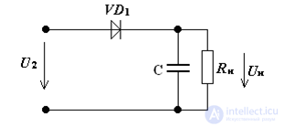
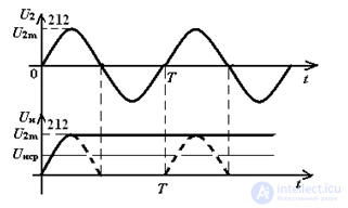
6. In a half-wave rectifier with a capacitive filter, Fig. 21, calculate Unsr and Uobrmax, if Cf = ∞, U2 = 150 V, the frequency of the network voltage is 50 Hz,
Rn = 2 kOhm, plot a timing diagram of the rectifier.
tasks and examples DIODES, RECTIFIERS

Solution:
Сф = ∞, therefore р = 0
Uнср =√2•U2 / (1 + р) = 212 В
Iнср = Uнср/ Rн = 212 / 2000 = 0,106 А
Iпрд = Iнср = 0,106 А
Uобр макс = 2√2•U2 = 424 В

Timing diagram of the rectifier .
tasks and examples DIODES, RECTIFIERS

7. In a full-wave bridge circuit of a rectifier with a filter, the voltage on the secondary winding of the transformer U2 = 150 V. The frequency of the mains voltage is 50 Hz, Rн = 2 kOhm, provided that the filter capacitance is ∞. Determine the average value of the rectified voltage Uнср, the value of the forward current through the diode Iпрд, Iнср, Uобрмах, the pulsation coefficient?

Solution:
Сф = ∞, therefore, р = 0
Uнср =√2•U2 / (1 + р) = 212 В
Iнср = Uнср/ Rн = 212 / 2000 = 0,106 А
Uобр макс = √2•U2 = 212 В

8. For a single-half-wave rectification circuit without a filter, Fig., determine the transformer transformation ratio, the maximum reverse voltage on the diode, if the rectified voltage on the load is 30 V and the voltage on the primary winding of the transformer is 220 V (50 Hz).
tasks and examples DIODES, RECTIFIERS

Solution:
Uнср =√2•U2/π = 30 В
U2 = 2,22 Uнср = 66 В
Uобр max = √2•U2 = 94 В
N= U1/ U2 = 220/66 = 3,33

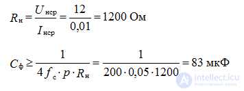
9. Determine the capacitance of the filter capacitor Сф in the bridge rectifier if the rectified voltage Uнср = 12 V, current Iнср = 10 mA, and the pulsation factor should not exceed 0.05.

Solution:
tasks and examples DIODES, RECTIFIERS

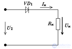
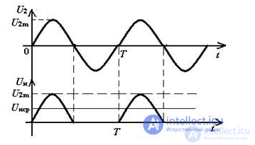
10. In a half-wave rectifier operating at Rн = 250 Ohm, the effective value of the voltage on the secondary winding of the transformer
U2 = 10 V.
Draw a diagram of a half-wave rectifier.
Determine with what permissible forward current it is necessary to select a semiconductor diode,
Draw timing diagrams of the input and output voltages of the rectifier.

Solution:
Uнср =√2•U2 / π = 4,5 В
Iнср = Uнср/ Rн = 4,5 / 250 = 0,018 А
Iпрд = Iнср = 0,018 А
Iпрдоп = 1,3• Iпрд = 0,0234 А

Timing diagram of the rectifier.
tasks and examples DIODES, RECTIFIERS

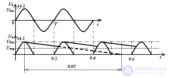
11. In a single-half-wave rectifier with a capacitive filter Fig., the voltage on the secondary winding of the transformer U2 = 10 V. The frequency of the mains voltage is 50 Hz, Rн = 1 kOhm, Сф = 80 μF.
Determine the average value of the rectified voltage Uнср, Iнср, Uобр max, the pulsation coefficient p, construct a timeth diagrams.

Solution:
Uнср =√2•U2 / (1 + р) = 14,1/(1 + 0,2) = 11,75 В
Uобр макс = 2√2•U2 = 28,2 В
τразр = С•Rн = 0,05 с
We construct timing diagrams:
tasks and examples DIODES, RECTIFIERS

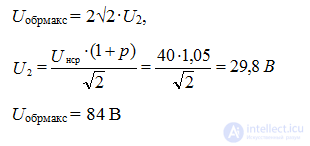
12. In a half-wave rectifier with a capacitive filter, the voltage on the load Uнср = 40. V, the pulsation coefficient should not exceed 0.05.
With what Uобрmax should you choose a semiconductor diode?

Solution
:tasks and examples DIODES, RECTIFIERS

See also

created: 2014-08-23
updated: 2025-01-07
3193


Rating 7 of 10. count vote: 2
Are you satisfied?:


Comments


To leave a comment
If you have any suggestion, idea, thanks or comment, feel free to write. We really value feedback and are glad to hear your opinion.
To reply

Electronics, Microelectronics, Element Base

Terms: Electronics, Microelectronics, Element Base