Lecture
Single ended differential amplifier
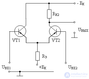
A simpler version of the circuit of an unbalanced differential amplifier is shown in Figure 4. 
Figure 4 Diagram of a single-ended differential amplifier.
In it, the left shoulder on the VT1 is an amplifier with a common collector. Resistor RE performs the same role as in a symmetrical differential amplifier. However, in an unbalanced amplifier, it is possible to remove the output voltage relative to a common point, which allows matching of this type of differential amplifier with single-phase voltage or power amplifiers.
Obtaining a voltage of different polarity at the output is provided by using a bipolar power supply –E and + Е. In accordance with the second Kirchhoff law, when passing from + Е to –Е through VT2, the potential passes through 0. Therefore, in quiescent mode, a mode is possible in which UOUT = 0 in the absence of voltages at the inputs.
When a U1 voltage of negative polarity is applied to the VT1 input, its collector current will increase, therefore, the collector current through VT2 will decrease (the current through Re will remain constant) when Ux2. This will lead to an increase in the positive potential at the output, since the voltage drop on Rk2 will decrease.
When UВХ1 = 0 and a negative potential at the input of VT2, it opens and the current through it increases, this will increase the voltage drop on Rк2 and, accordingly, the potential at the output will decrease. Those. output voltage will change polarity. With the same magnitude and sign of the potentials at the inputs, the output voltage will be zero, since the collector current of transistors VT1 and VT2 will not change.
One of the inputs of an unbalanced differential amplifier has a consistent potential sign with the output and is therefore called non-inverting. The input of the differential amplifier, the sign of the potential of which is opposite to the sign of the output potential, is called inverting.
Main settings
1. Uout = U21 = Ku * (Uin1 - Uin2)
2. Rin du = 2h11
3. Rvykh du = 2Rk / (1 + h22Rk) "2Rk 
The DUs are used: in the OS as an input main stage, in stabilizers; in the form of separate integrated circuits. K118 UD1, K122 UD1, K175 HC series and others
Comments
To leave a comment
Electronics, Microelectronics, Element Base
Terms: Electronics, Microelectronics, Element Base