Lecture
Digital to Analog Converters (D / A Converters) and Analog-to-Digital Converters (A / D Converters)
The main parameters of the DAC and ADC
• Bit width, expressed in bits, which characterizes the measurement range of the input quantity.
• Transmission error, indicating the difference between the actual and prescribed values (in the least significant units).
• Linearity of the characteristic, i.e. the presence of proportionality between the standard of the analog value and the code corresponding to this value in units of the lower order.
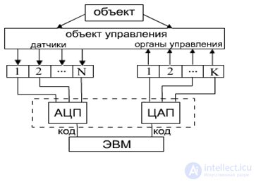
The possibility of using the DAC and ADC

D / A converters

where z0, z1, z2, z3 are coefficients taking the value "0" or "1" with the corresponding key closed or open.
4-bit binary code is converted to the output voltage level in the range (0 ÷ 15) ΔU, where ΔU is the quantization step. The smaller ΔU, the greater the bit width of the DAC
Analog-to-Digital Converters
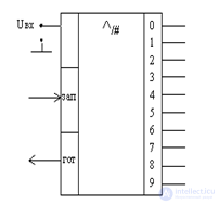
ADC designation

ADC - analog-to-digital converter is a special type of encoder.
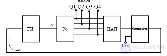
The principle of operation of the ADC: using the method of sequential counting.
The principle of operation of the ADC

The pulse generator GI generates a sequence of pulses, which are converted into binary code using the MF counter. This code controls the DAC keys. The output voltage of the DAC is fed to one of the inputs of the comparator. In case of equal voltages Uin and Ucap, the comparator outputs a signal that stops the operation of the GI. At the output of the counter is fixed binary code corresponding to the voltage Uin
Comments
To leave a comment
Electronics, Microelectronics, Element Base
Terms: Electronics, Microelectronics, Element Base