Lecture
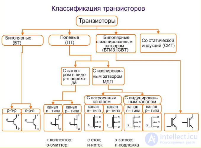
Transistors
Bipolar, field, JGBT.
Bipolar transistors
The bipolar transistor is a semiconductor three-layer npn or pnp structure and is designed to amplify the power of electrical signals.
The scheme of the technological structure of the bipolar transistor and its symbols are shown in fig. one.
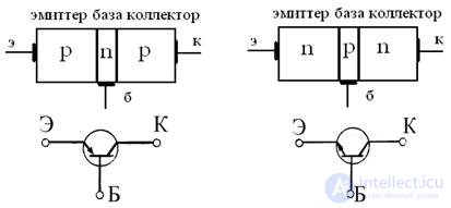
Fig. 1 Schemes of technological structures of bipolar transistors
and their conventions.
The internal structure of the transistor
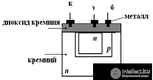
Wiring transistor
These three layers have the following names: emitter (E), base (B), collector (K). To enhance the electrical power, three options are used to turn on the bipolar transistor: with a common emitter (OE), a common base (ON) and a common collector (OK).

Figure 2 Wiring transistor
Modes of operation of the transistor
1. Active (booster)
2. Saturation mode
3. Cutoff mode
Tatic current-voltage characteristics of BPT
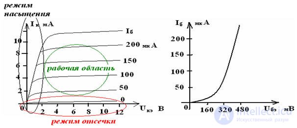
Pic 3
Amplification properties of the transistor
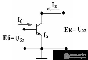
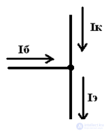
common emitter transistor circuit
Proof: let
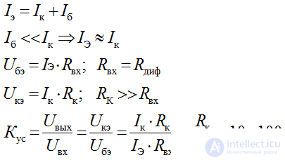
The transistor is controlled by the base current
The replacement circuit of a bipolar transistor
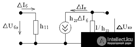
Pic 4
The relationship between input and output currents and voltages in the transistor, presented in the form of an equivalent quadrupole, is expressed by the system of equations of the electrical state:

h - transistor parameters
transistor input resistance

feedback ratio

DC gain

output conductivity

One of the main parameters of a bipolar transistor is the current transfer ratio. When operating in DC mode for a common base circuit, this is the ratio of the collector current to the emitter current

For a common emitter circuit, the current transfer ratio in DC mode is equal to the ratio of the collector current to the base current
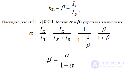
In addition, as in the quadrupole, the transistor other main parameters are the input and output resistances, which characterize the consistency of the input and output circuits of the transistor with other quadripoles.
Graphic definition of h - transistor parameters
Uke = Ek - Ik • Rk - line load
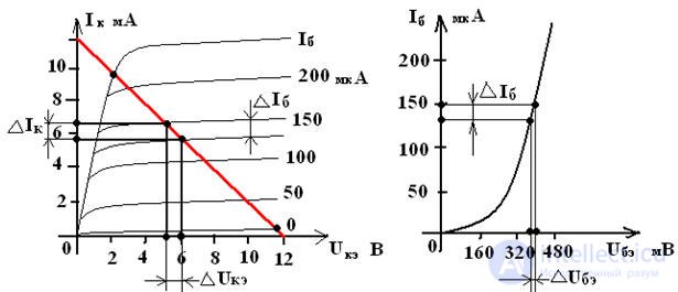
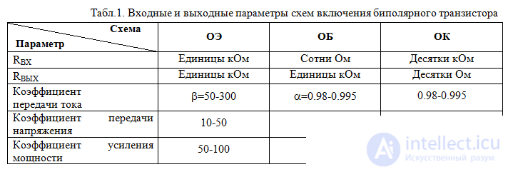
Table 1 shows the comparative parameters of these inclusion schemes.
Comments
To leave a comment
Electronics, Microelectronics, Element Base
Terms: Electronics, Microelectronics, Element Base