Lecture
Smoothing Filters
At the output of the rectifier, a pulsating constant voltage is obtained. For many electronic devices, the ripple factor of the supply voltage should not exceed p = 10-2 - 10-5. Therefore, smoothing filters are used to reduce pulsation.
Filters are usually performed on reactive elements: capacitors and chokes. Here, the reactive properties of these elements are used: in a series connection - the choke has a high resistance to alternating current; with parallel connection - the capacitor has a small resistance to alternating current. A feature of filters is that the filter capacity better smoothes pulsations at low load currents, and an inductive filter, on the contrary, at high currents.
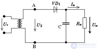
The capacitive filter is always switched on parallel to the load. Consider a half-wave rectifier with a smoothing capacitive filter Fig.3.

Fig. 3 Half-wave rectifier circuit with capacitive filter
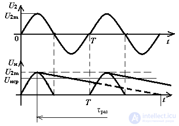
The smoothing principle is as follows (Fig. 4) for the circuit in Fig. 3: in the first half period (0 - T / 2), when the potential of point A is higher than the potential of point B, the diode VD1 is open and the capacitor is charged through a low internal resistance of the diode to U2max . When the potential of point A is lower than the voltage on the capacitor, in the second half period (T / 2 - T) the diode is closed and the capacitor discharges through the load resistor Rн until the potential of point A is higher than the voltage on the capacitor.

Fig. 4 Timing diagrams of a half-wave rectifier with a capacitive filter
The voltage on the locked diode will be determined according to the second Kirchhoff law:
Uomax = Uc + U2max
moreover, the capacitor is charged to the value of U2max, which means:
for half-wave rectifier:
Uomax = 2 • U2max = 2√2 U2
for full-wave rectifier:
Uobrmax = U2max = √2 U2
The average rectifier voltage of the rectifiers with a filter is determined by the formula

Comments
To leave a comment
Electronics, Microelectronics, Element Base
Terms: Electronics, Microelectronics, Element Base