
Lecture
The following methodologies are used for the logical design of relational data warehouses (DW).
let us consider the "entity-relationship" modeling method.
The main purpose of information systems (IS), including data warehousing systems, is to promptly provide the user with information about the outside world by implementing a question-answer relation. Question-answer relations, once interpreted in the outside world (the world outside the IS), make it possible to single out for the IS a specific fragment of it — the domain — which will be embodied in the system. Information about the outside world is represented in the IS in the form of data. This limits the possibilities for semantic interpretation of the information and makes the semantics of its representation in the IS more concrete. The set of these selected data items for the IS forms the logical model of the domain, describing its state with a certain degree of accuracy.
It is important to understand that the logical model of the domain is created at the stage of analyzing the requirements for the IS and does not contain any assumptions about the technology used to implement the warehouse or database.
Operating with the terms "data" and "questions", the question-answer relation can be represented as a table whose columns are data elements and whose rows are questions. Each cell of such a table has the logical value 1 if the question uses that data element, or 0 otherwise.
The concept of the domain is one of the basic concepts of computer science and has no exact definition. Its use in the context of an IS presupposes the existence of a correspondence, stable over time, between names, concepts, and specific realities of the outside world, independent of the IS itself and its circle of users. Thus, introducing the concept of the domain limits and makes tractable the space of information retrieval in the IS, and allows queries to be executed in finite time.
The set of realities (objects) of the outside world — objects about which questions can be posed — forms the object core of the domain. It is impossible for an IS to answer a question about something it does not know.
The term "object" is a primary, undefined concept. Synonyms for the term "object" are "reality", "entity", "thing". Note that the term "entity" is understood further in a somewhat narrower sense, as a component of a specific logical model of the domain. Objects singled out in the domain are turned by analysts (not designers) into entities. Here, a domain entity is understood as the result of abstracting a real object by identifying and fixing its properties.
Fig. 6.1 shows one of the approaches to classifying domain objects.
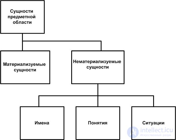
Examples of entities (from the point of view of the logical model of the domain) or objects (from the point of view of the outside world relative to the IS) include: a student, a group of students, a classroom, class time, etc.
Two problems are associated with objects — identification and adequate description. A name is used for identification. This assumes that its meaning, inherent in natural language, is set aside; only the referential function of the name is used. A name is a direct way of identifying an object. Indirect ways of identifying an object include its properties, understood as characteristics or attributes.
Objects interact with one another through their properties, which gives rise to situations. Situations are relationships that express interactions between objects. Situations in the domain are described by means of statements about the domain using propositional calculus and predicate calculus, i.e., formal, mathematical logic. For example, the statement "A programmer and a manager are employees of the company" describes an inclusion relation. Thus, all information about objects and entities of the domain is described by means of statements in natural language.
Methods of mathematical logic make it possible to formalize these statements and present them in a form suitable for analysis.
Example.
Consider the statement: "Student Ivanov A.A. was born in 1992". It expresses the following properties of the object "Ivanov A.A.":
The first property establishes a connection between the pair of objects "Ivanov A.A." and "year of birth", while the second property establishes a connection between the pair of objects "Ivanov A.A." and "the set of students". The formalization of this statement is represented as the result of assigning values to the variables occurring in the following predicates:
| РОДИЛСЯ (Иванов А.А., 2032) |
| ЯВЛЯЕТСЯ СТУДЕНТОМ (Иванов А.А.) |
Note that in the semantics of natural languages, a situation and a relationship are considered nearly synonymous. A situation contains a statement about objects of the domain, to which a certain truth value can be assigned and which can be represented as a predicate once variables have been introduced. Thus, the set of statements about the domain can be treated as defining the information space for the IS.
Fig. 6.2 shows one of the approaches to classifying situations within the domain.
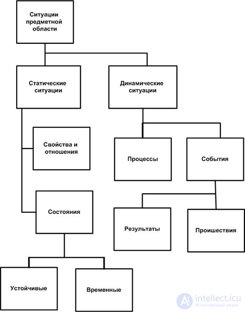
A distinction is made between static and dynamic situations. Examples of static situations include such situations as "having a color", "having an age", etc. Examples of dynamic situations include such situations as "building a mechanism", "baking bread", etc.
Note that a situation can itself also be an object and possess properties. This kind of collision creates ambiguity when modeling the domain.
The classification given above introduces two important aspects into the domain – space and time, where time is understood both as a point in time and as an interval between events. The domain exists in space and time, i.e., like the real world, it has temporal and spatial relations and connections inherent to it. A distinction should be made between the real time of the outside world and its reflection in the IS and in the sources of information. In an IS, time-dependent relationships are recorded only after they are registered. Thus, at any given point in time the domain represents a selected set of specific objects and situations, called the state of the domain (or snapshot).
Thus, the domain is a purposeful, primary transformation of the picture of the outside world into a certain speculative picture, a certain part of which is fixed in the IS as an algorithmic model of a fragment of reality.
The concept of the domain was introduced in the early 1980s, when researchers in the field of IS realized the need to use semantic models to represent information in computer systems. Just as the requirements for a computer system are formed by means of natural language, so information in computer systems is represented by means of a special language with a defined semantics. This approach was first presented by P. Chen in 1976.
An example of a classic domain for building data warehousing systems, and hence for a DW, is the task of analyzing a company's sales. The objects that can be identified in this domain include: "sales manager", "product", "warehouse", "sales office", "customer". Examples of situations include – "sell a product", "buy a product", "ship a product from the warehouse", "deliver a product".
A DW is, by definition, a subject-oriented, integrated collection of historical data that is constant over time and is used by various groups of users to support decision-making or data analysis. Information in computer systems, including in a DW, is represented in the form of data items. One of the basic tenets of the DW concept is to clean, filter, transform, summarize, and aggregate data, and then place it in some structure in order to meet the information needs of users. Defining such a structure is one of the main tasks of logical DW modeling.
One of the first tasks facing a DW designer is defining the data architecture. Data architecture is the set of principles governing the subjective representation of information in the form of data within the framework of a domain model. When building the data architecture, the DW designer defines the data elements, their properties, and the relationships between them. One of the key issues in building a data architecture is the level of detail of the information when it is converted into data elements. This conversion process is called data structuring.
For data in OLTP systems, resolving issues related to the level of data detail is not as important as it is for data warehousing systems. In the databases of OLTP systems, data is usually structured in fine detail. When representing data in a DW, the designer must specifically decide on the level of data structuring, based on the requirements for the data warehousing system. This decision is quite important, since during aggregation and summarization some data ranges from the source OLTP system may not be represented in the DW. For example, a telecommunications company's DW may store phone usage charges summed by the minute, while the source system stores such data by the second.
Data granularity (the level of structuring, detail, or granularity of data) is one of the most important characteristics of a DW. Data granularity is the degree of detail of stored data that is optimal from the point of view of solving information-analytical problems within the domain of the DW.
Roughly speaking, data granularity determines the number of queries that can be answered by the data warehousing system. If the DW supports a high level of data granularity, the system can support practically any query within the domain of the DW. In the example given above, it is impossible to answer the question of how much subscriber Ivanov A.A. paid for five seconds of a call on January 1, 2009.
Supporting a high level of data granularity requires storing and maintaining large volumes of data, which can negatively affect the performance of the data warehousing system, in particular the query response time. On the other hand, a low level of data granularity means that the data warehousing system can only answer a strictly limited range of queries. Therefore, one of the tasks facing a DW designer at the level of logical modeling is deciding on the optimal level of data granularity in the DW.
Data structuring involves splitting the entire data set into certain classes with a view to further detailing within each selected class. Three main types of data (classes) are characteristic of a DW.
The concept of the domain is used in practically all classes of information systems with databases and data warehouses, both in their design and development. The domain defines the part of the real world that will be modeled and implemented in the system. The domain defines the most general criteria and requirements for the system that follow from its semantics.
A DW is by definition a subject-oriented electronic collection, i.e., it is oriented from the outset toward specific areas of an organization's activity, a domain — for example, such as manufacturing or sales.
The questions users address to a DW are, as a rule, more strategic and more general in nature than in OLTP systems. Answering them involves aggregating and summarizing data across various areas of the organization's activity. This requires DW-based systems to be oriented toward specific domains of the organization's activity.
Domains in DW-based systems are formed in accordance with the organization's areas of activity. To determine the list of domains for such systems, it is necessary to identify the organization's main activities — for example, sales, manufacturing, customers, and so on.
To identify domains in a DW, the so-called "SW1 rule" methodology is often used, namely, answering the questions: when, where, who, what, why, and how – with respect to the organization's activities (business interests). For example, when answering the question "who", business interests may cover the following objects: "customers", "employees", "suppliers", "managers", "business partners", etc.
After building a list of potential domains for DW-based systems, they are usually further detailed by decomposing each domain. As a result, a list of domains can be obtained that most fully represents the organization's activity. In doing so, it is important to define the relationships between the identified domains, which is important for defining dimensions in dimensional modeling of the DW.
Note that when solving analysis problems, and hence when developing BI systems, the most promising approach for defining the domain is to study the organization's business processes, rather than its functions, as is the case with OLTP systems.
Next, we will look at the "entity-relationship" modeling method. This method is used to represent the domain in the form of its logical model. Applying this method creates a model of the domain that is independent of the implementation. The method is applied both when modeling the domains of OLTP systems and when modeling the domains of BI systems. Knowledge of this method helps the DW designer more quickly establish logical connections between the database models of organization-wide OLTP systems and the DW models of BI systems.
The result of modeling with the "entity-relationship" method, or ER modeling, is an ER model. An ER model is represented using ER diagrams, which are a graphical notation for abstracting data in the form of entities, relationships, and attributes. Thus, the semantics of the domain is represented in the ER model in terms of subjective descriptive means – entities, attributes, entity identifiers, supertypes, subtypes, and so on.
A domain entity is the result of abstracting a real object by identifying and fixing a set of its properties. Thus, an entity represents a class of objects that is the result of abstracting a real object. Entities are usually denoted by a natural-language noun.
An entity is described by means of data called properties or attributes of the entity. As a rule, attributes are definitions within a statement about the entity and are denoted by natural-language nouns.
Entities enter into relationships with one another through their attributes. Each group of attributes describing one real manifestation of an entity constitutes an instance of the entity. In other words, an entity instance is a realization of the entity that differs from other realizations and allows unambiguous identification. Naming an entity in the singular makes the model easier to read later on. In fact, the entity's name is derived from the name of its instance.
One of the main computer-based ways of recognizing entities in an IS is assigning identifiers (Entity identifier) to entities. An entity identifier is often called a key. Choosing an entity identifier is a semantically subjective task. Since an entity is defined by a set of its attributes, it is advisable for each entity to select a subset of attributes that unambiguously identifies that entity.
Some entities have natural identifiers. For example, the natural identifier of an invoice is its number. Entity identifiers can be composite — consisting of several attributes — or atomic — consisting of a single attribute of the entity.
A unique entity identifier is an entity attribute that allows one entity to be distinguished from another. If an entity has several unique identifiers, so-called candidate keys, the designer must choose the primary key of the entity.
A distinction is made between single-valued and multi-valued attributes. Single-valued attributes are those that, within a given entity instance, have only one value. Otherwise they are considered multi-valued.
An important point when a designer studies the domain model is identifying multi-valued attributes of an entity. This is because the relational model does not support multi-valued attributes, and they must be resolved at later stages of design.
Every attribute has a domain. A domain is an expression that defines the values allowed for a given attribute. In other words, a domain is the range of values of an attribute. A domain must be defined for each attribute of an entity. At the level of logical data modeling, assigning a domain to an attribute is of a general nature. For example, an attribute is textual, numeric, binary, a date, or "undefined". In the latter case, the analyst must provide a description of the domain. At later stages the domain type is made more specific; the meaning of the concept of a domain in the physical model of a DW is narrower than what the analyst might understand by it. This is because, within a physical model, a domain is implemented via a domain constraint mechanism, and the DBMS does not understand undefined domains.
Entities do not exist separately from one another. There are real relationships (Relationship) between them, which must be reflected in the domain model. When identifying relationships, the emphasis is on capturing the connections and their characteristics. A relationship (connection) is a connection (interrelation) between two or more entities. Each relationship is realized through the values of entity attributes. A relationship is usually denoted by a verb. Each relationship must also have its own unique relationship identifier.
In the relational model, relationships are implemented only through foreign-key referential integrity constraints. Therefore, the designer of a relational DW must make sure that the relationship between entities is realized through precisely specified attributes, which will define the unique key of the relationship. The choice of entity keys is one of the most important design decisions the designer will have to make when moving to the physical database model.
Relationships are characterized by the degree of the relationship and the entity's class of membership in the relationship. The degree (cardinality) of a relationship is the ratio of the number of entities participating in forming the relationship. For example, "one-to-one", "one-to-many", "many-to-many". At the logical model level, an undefined or unresolved relationship is allowed. The entity's class of membership is the nature of the entity's participation in the relationship. A distinction is made between mandatory and optional classes of entity membership in a relationship. Membership is mandatory when instances of the entity must necessarily participate in establishing the relationship. Otherwise the entity belongs to the optional class of membership. For an optional class of entity membership, the degree of the relationship can be equal to zero, i.e., an entity instance can be linked to 0, 1, or several instances of another entity. For a mandatory class of membership, the degree of the relationship cannot be zero.
Relationships that link an entity to itself are called reflexive. A typical example of reflexive relationships is defining the reporting structure in the "Employees" relationship. Reflexive relationships most often reflect hierarchical relationships within the data structure. They give rise to a number of design problems, which will be discussed later
From the point of view of relationships, a distinction is made regarding weak entities (weak). Weak entities are entities that cannot be present in the database unless an instance of another related entity already exists. An example of such an entity is an order, which cannot exist without a customer. Weak entities have a mandatory class of membership, and the degree of the relationship for such an entity cannot be zero. The "order-customer" relationship is mandatory.
Identifying weak entities and their associated mandatory relationships is necessary to ensure data integrity and consistency. For example, an order cannot be assigned to an unknown customer.
Sometimes an identified entity carries within it an inclusion relationship, or a "part-whole" relationship. In this case there is some attribute whose values give rise to splitting the set of entity instances into disjoint subsets — entity categories. Entity categories are called subtypes, and a subordinate entity is identified within the relationship, which is a category of the original entity. Attributes common to the resulting categories are extracted from the original entity, and thus an entity is identified that becomes the supertype. The identified supertype entity is usually left with the name of the original entity, although its semantic meaning changes.
A supertype together with the subtypes it generates is an example of a so-called composite entity. A composite entity is a logical construct of the model for representing a set of entities and the relationships between them as a single whole.
Example. The entity "car" can be split into the following subtypes: two-wheel-drive cars, four-wheel-drive cars, cars with switchable drive.
It is important for the designer to know that every instance of a supertype entity belongs to only one of its subtypes. The presence of subtypes and supertypes in the model complicates the design and creates certain implementation difficulties. Therefore it is important, at an early stage of design, to establish whether the presence of supertypes in the model is necessary.
To do this, the following steps must be taken:
A typical form of documenting the logical model of the domain in ER modeling is "entity-relationship" diagrams, or ER diagrams (Entity Relationship Diagram). An ER diagram makes it possible to graphically represent all the elements of the logical model according to simple, intuitively understandable, but strictly defined rules — notations.
One of two most widely used notations is usually used to create ER diagrams.
ER diagrams are typically constructed using CASE tools. In this lecture, unless stated otherwise, all examples will use the MS Office Visio 2007 notation.
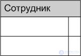
On an ER diagram, an entity is represented by a rectangle with its name at the top (Fig. 6.3).
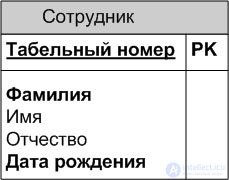
The rectangle lists the entity's attributes, and the attributes that make up the entity's unique identifier are underlined (Fig. 6.4).
Every entity instance must be unique and distinguishable by its other attributes. One of the main computer-based ways of recognizing entities in an IS is assigning identifiers (entity identifier) to entities. Since an entity is defined by a set of its attributes, it is advisable for each entity to select a subset of attributes that unambiguously identifies that entity. An entity identifier is often called the primary key (primary key).
The primary key (primary key) – is an attribute or group of attributes that unambiguously identifies an entity instance. Primary key attributes require no special designation on the diagram – they are simply the attributes that appear in the attribute list above the horizontal line (Fig. 6.3).
Choosing a primary key can turn out to be a nontrivial task, one whose resolution can affect the efficiency of the future IS. A single entity may have several attributes or sets of attributes vying for the role of primary key. Such contenders are called candidate keys (candidate key).
Keys can be composite, i.e., contain several attributes. Composite primary keys require no special designation – they are simply the list of attributes above the horizontal line.
Let's consider the candidates for the primary key of the "employee" entity (Fig. 6.5).
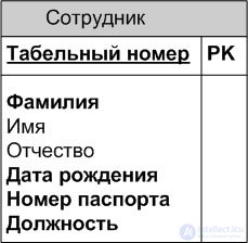
Here we can identify the following candidate keys.
To become primary, a candidate key must satisfy a number of requirements.
Uniqueness. No two instances should have identical values of a candidate key. The candidate key ( Last name + First name + Patronymic ) is a poor candidate, since an organization may employ two people with exactly the same full name.
Compactness. A composite candidate key should not contain a single attribute whose removal would not cause uniqueness to be lost. To ensure the uniqueness of the key ( Last name + First name + Patronymic ), let us supplement it with the attributes Date of birth and Eye color. If the business rules state that the combination of attributes Last name + First name + Patronymic + Date of birth is sufficient to uniquely identify an employee, then Eye color turns out to be superfluous, i.e., the key Last name + First name + Patronymic + Date of birth + Eye color is not compact.
When choosing a primary key, preference should be given to simpler keys, i.e., keys containing fewer attributes. In the example, keys No. 1 and No. 2 are preferable to key No. 3.
Key attributes must not contain null values. If it is allowed that an employee may not have a passport, or may have some other form of identification instead of a passport, then key No. 2 is not suitable as a primary key. If it is necessary to supplement a candidate key with additional attributes to ensure uniqueness, those attributes must not contain null values. When supplementing key No. 3 with the attribute Date of birth, one must make sure that the dates of birth are known for all employees.
The value of key attributes must not change throughout the lifetime of the entity instance. An employee of an organization can get married and change both her surname and her passport. Therefore keys No. 2 and 3 are not suitable candidates for the primary key.
Every entity must have at least one candidate key. Many entities have only one candidate key. Such a key becomes the primary key. Some entities may have more than one possible key. In that case one of them becomes the primary key, and the rest become alternate keys. An Alternate Key is a candidate key that did not become the primary key.
Some entities have natural keys. For example, the natural identifier of an invoice is its number. Otherwise, the designer can create a Surrogate Key – an attribute whose value is artificially generated and has no relation to the subject domain. When modeling data structures for a data warehouse, surrogate keys are often preferable.
Domains are assigned by analysts and recorded in a special document — the Data Dictionary. When building a logical model, domains can be specified for entities on the ER diagram.
Every attribute has a domain. A domain can be defined as an abstract attribute on the basis of which ordinary attributes can be created, with the created attributes inheriting all the properties of the parent domain. Each attribute can be defined on only one domain, but many attributes can be defined on each domain. The concept of a domain includes not only the data type but also the range of valid values. For example, one could define the domain "Age" as a positive integer and define the attribute Employee Age as belonging to this domain.
At the logical data modeling level, assigning a domain to an attribute is done in a general way. For example, an attribute is text, numeric, binary, date, or "undefined". In the latter case the analyst must provide a description of the domain. At later stages the domain type is made more specific; the meaning of the domain concept in the physical data warehouse model is narrower than what the analyst may understand by it. This is because within the physical model a domain is implemented via a domain-constraint mechanism, and the DBMS does not understand undefined domains.
The designer must carefully study the domains of each attribute in terms of their feasibility in the DBMS and, together with the analysts, make changes to them if the feasibility condition is not met. In doing so the designer is guided by the following:
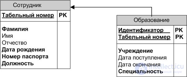
A relationship between entities on an ER diagram is depicted as a line connecting those entities. The relationship is read along the line either from left to right or from right to left. Fig. 6.6 shows the following relationship: each specialty by education must be registered to a specific individual (person), and an individual may have one or more specialties by education.
продолжение следует...
Часть 1 The entity-relationship modeling method
Часть 2 See also - The entity-relationship modeling method

Comments