
Lecture
Это окончание невероятной информации про метод моделирования сущность-связь.
...
font-size: 12px;">
In MS Office Visio, the relationship name, the relationship degree (cardinality), and the entity's membership class in the relationship are defined on the "Database Properties" tab, as shown in Fig. 6.7. The arrow on the relationship line points to the parent table.

When identifying relationships, the focus is on discovering their characteristics. A relationship represents an interconnection between two or more entities. Each relationship is realized through the values of entity attributes; for example, an instance of the "Employee" entity (Fig. 6.6) is linked to an instance of the "Education" entity through matching values of the Employee ID attribute. In other words, when a relationship is created, one of the entities, called the child entity, gains a new attribute called a foreign key (FK) (in Fig. 6.6 this is the Employee ID attribute). Foreign key attributes are sometimes marked with the symbol (FK) after their name.
A relationship is a logical correlation between entities. Every relationship must be named with a verb or verb phrase: Relationship Name (Verb Phrase) – a phrase describing the relationship between the parent and child entities. The relationship name expresses some constraint or business rule and makes the diagram easier to read. Fig. 6.8 shows how a relationship is assigned a name.

There are various types of relationships: an identifying relationship "one-to-many", a "many-to-many" relationship, and a non-identifying relationship "one-to-many". Different entity types are also associated with different relationship types.
There are two types of entities: dependent (Dependent entity) and independent (Independent entity). The type of an entity is determined by its relationship with other entities. An identifying relationship is established between an independent entity (the parent end of the relationship) and a dependent entity (the child end of the relationship).
An instance of a dependent entity is defined only through its relationship to the parent entity, i.e., in the structure in Fig. 6.8 information about a specialty cannot be entered and has no meaning without information about the employee who holds that specialty according to their education diploma. When an identifying relationship is established (shown as a solid line in the figure), the primary key attributes of the parent entity are automatically migrated into the primary key of the child entity (solid line). This operation of adding attributes to the child entity when creating a relationship is called attribute migration. In the child entity, such an attribute is considered a foreign key.
If the model is created using CASE tools, then when the database schema is generated, the primary key attributes will receive the NOT NULL property, which means it is impossible to insert a record into the "Employees" table without information about the employee's ID number.
When a non-identifying relationship is established (Fig. 6.9, dashed line), the child entity remains independent, and the primary key attributes of the parent entity migrate as non-key components of the child entity. A non-identifying relationship is used to link independent entities (Fig. 6.9).
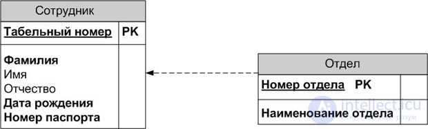
An instance of the "Employee" entity can exist regardless of any instance of the "Department" entity, i.e., an employee can work at the organization without being assigned to any department.
An identifying relationship is shown on the diagram as a solid line with a solid dot at the child end (see Fig. 6.8), while a non-identifying one is shown as a dashed line (see Fig. 6.9).
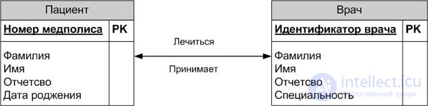
A "many-to-many" relationship (many-to-many relationship) can only be created at the logical model level. Fig. 6.10 shows an example of defining a many-to-many relationship. A doctor can see many patients, and a patient can be treated by several doctors. Such a relationship is denoted by a solid line with arrowheads at both ends.
A "many-to-many" relationship must be named with two phrases – one for each direction (in the example, "treats/is treated by"). This makes the diagram easier to read. The relationship in Fig. 6.10 should be read as: Doctor
As noted above, relationships determine whether an entity is independent or dependent. There are several types of dependent entities.
Characteristic – a dependent child entity that is related to only one parent and, by its meaning, stores information about the characteristics of the parent entity.
Associative – an entity related to several parent entities. Such an entity contains information about the relationships between entities.
Naming – a special case of an associative entity that has no attributes of its own (only attributes of parent entities that migrated in as foreign keys).
Categorical – a child entity in an inheritance hierarchy.
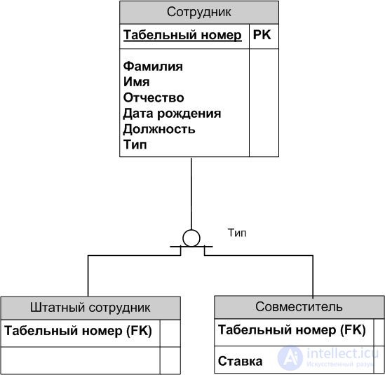
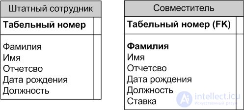
An inheritance hierarchy (subtype relationship), or category hierarchy, is a special type of grouping of entities that share common characteristics. For example, an organization employs full-time staff (regular employees) and part-timers. From their common properties one can form a generalized entity (a generic ancestor) "Employee" (see Fig. 6.11) to represent information common to all types of staff. Information specific to each type can be placed in the categorical (descendant) entities "Regular Employee" and "Part-Timer".
An inheritance hierarchy is usually created when several entities have attributes that are conceptually shared, or when entities have conceptually shared relationships (for example, if "Regular Employee" and "Part-Timer" had a similarly meaningful "works at" relationship with the "Organization" entity), or when this is dictated by business rules.
For each category one can specify a discriminator – an attribute of the generic ancestor that shows how to distinguish one categorical entity from another (the Type attribute in Fig. 6.11).
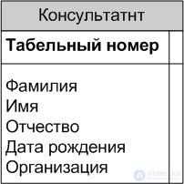
Category hierarchies are divided into 2 types – complete and incomplete. In a complete category hierarchy (Complete subtype relationship), every instance of the generic ancestor (the "Employee" entity, Fig. 6.12) must necessarily correspond to an instance in one of the descendants, i.e., in this example an employee must necessarily be either a part-timer, a consultant, or a permanent employee.
If a category has not yet been fully built out, and instances may exist in the generic ancestor that have no corresponding instances among the descendants, then such a category is incomplete (Incomplete subtype relationship). Fig. 6.11 shows an incomplete category – an employee can be not only permanent or a part-timer, but also a consultant, however the "Consultant" entity has not yet been added to the inheritance hierarchy.
Fig. 6.12 shows an example of a complete category.
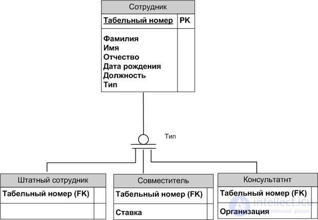
A complete category is marked with the symbol , an incomplete one with–
 .
.
A combination of complete and incomplete categories is possible. Besides permanent employees and part-timers there may also be consultants, who may not be reflected in the hierarchy (incomplete category), but every permanent employee is either male or female (complete category).
Let us consider the possible stages of building an inheritance hierarchy.
Suppose that during the design process the entities "Regular Employee" and "Part-Timer" were created (Fig. 6.13). One can notice that some of the attributes of these entities (Last Name, First Name, Middle Name, Date of Birth, Position) have the same meaning.
There are 3 sublevels of the logical level of the data model, differing in the depth of representation of information about the data:
The entity-relationship diagram (ER diagram) displays the entities and interrelationships that reflect the main business rules of the subject domain; it includes the principal entities and the relationships between them that satisfy the basic requirements imposed on the information system. An entity-relationship diagram can show many-to-many relationships and need not include a description of keys. As a rule, ER diagrams are used for presentations and for discussing the data structure with subject-matter experts.
The key-based data model is a more detailed representation of the data. It includes a description of all entities and primary keys, and is intended to represent the data structure and keys that correspond to the subject domain.
The fully attributed model is the most detailed representation of the data structure: it represents the data in third normal form and includes all entities, attributes, and relationships.
Let us now consider the process of data normalization, which accompanies the creation of the fully attributed model.
Normalization – the process of checking and reorganizing entities and attributes in order to satisfy the requirements of the relational data model. Normalization ensures that every attribute is defined for its own entity, significantly reduces the amount of storage needed to hold the information, and eliminates anomalies in the way data is organized for storage. As a result of normalization, a data structure should be created in which information about each fact is stored in only one place.
The normalization process consists of successively bringing the data structure into normal forms – formalized requirements for the organization of data. Six normal forms are known:
In practice, one is usually limited to bringing data to third normal form. In this section the first three normal forms will be covered fairly briefly, along with fourth normal form as an illustration. For an in-depth study of normalization, the book [Date] is recommended.
Normal forms are based on the concept of functional dependency (hereafter the term "dependency" will be used). Let us give a formal definition of functional dependency.
Functional dependency (FD). Attribute B of entity E is functionally dependent on attribute A of entity E if and only if each value of A in E is associated with exactly one value of B in E, i.e., A uniquely determines B.
Full functional dependency. Attribute B of entity E is fully functionally dependent on a set of attributes A of entity E if and only if B is functionally dependent on A and is not dependent on any proper subset of A.
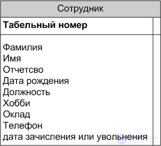
In Fig. 6.15, in the "Employee" entity, the values of the attributes Last Name, First Name, and Middle Name are uniquely determined by the value of the Employee ID attribute, i.e., the attributes Last Name, First Name, and Middle Name depend on the Employee ID attribute.
Functional dependencies are determined by the business rules of the subject domain. Thus, if an employee's salary is determined only by their position, then the attribute Salary depends on the attribute Position; if the salary also depends, for example, on length of service, then no such dependency exists. In the examples below, for the sake of concreteness, we will assume that such a dependency does exist.
Let us consider the normal forms.
First normal form (1NF). An entity is in first normal form if and only if all attributes contain atomic values.
Attributes must not contain repeating groups, i.e., several values for each instance. In Fig. 6.15 the attributes Phone and Hobby may represent repeating groups and thereby violate the requirements of first normal form. An employee may have several work phone numbers or have several hobbies (fishing, hunting, swimming). Adding several attributes to the entity to represent the values of the repeating group is not a solution to the problem, since in most cases one cannot know in advance exactly how many such values there may be.
Storing values with different meanings in a single attribute violates the normalization requirements. In Fig. 6.15 the attribute Date of Hire or Termination stores information about both hiring and termination of an employee. If only one value is stored, it is impossible to tell which date has been entered. If a type flag attribute for the date is added, the type can be determined, but it would still only be possible to store one date per employee.
To bring an entity to first normal form, one should:
Fig. 6.16 shows the "Employee" entity brought to first normal form.
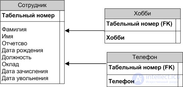
Second normal form (2NF). An entity is in second normal form if it is in first normal form and every non-key attribute is fully dependent on the primary key (there must be no dependency on part of the key). Second normal form is meaningful only for entities that have a composite primary key.
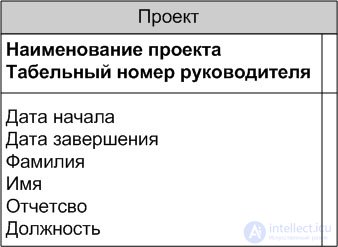
Suppose the "Project" entity contains information about a project managed by an employee, with the information covering both the project itself and the project manager (Fig. 6.17). The attributes Last Name, First Name, Middle Name, and Position depend only on the attribute manager's employee ID, but not at all on the attribute Project Name. In other words, there is a dependency on only part of the key.
To bring an entity to second normal form, one should:
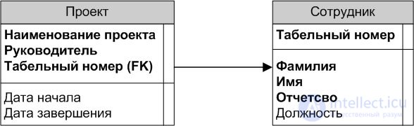
Second normal form helps avoid the following anomalies when performing operations:
Fig. 6.18 shows the "Project" entity brought to second normal form.
Third normal form (3NF). An entity is in third normal form if it is in second normal form and no non-key attribute depends on another non-key attribute (there must be no interdependency among non-key attributes).
In Fig. 6.16 the "Employee" entity is in second normal form (there is only one primary key attribute, so there can be no dependency of non-key attributes on part of the key), but the non-key attribute Salary depends on another non-key attribute – Position.
To bring an entity to third normal form, one should:
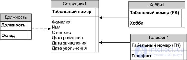
In third normal form, every attribute of an entity depends on the key, on the whole key, and on nothing but the key.
Third normal form also helps avoid a number of anomalies.
Fourth normal form (4NF) requires the absence of multivalued dependencies between attributes.
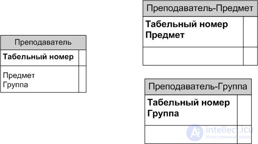
In the example in Fig. 6.20 (left), an instructor teaches lectures on several subjects and supervises several student groups. One student group may study several subjects, and one subject may be taught to several student groups. There is a multivalued dependency between the attributes Subject and Group. This can produce an anomaly: if an instructor gets a new group, several records must be added, one for each subject they teach.
To bring an entity to fourth normal form, one should create a new entity and move the attributes with the multivalued dependency into separate entities (Fig. 6.20, right). A relationship between the new entities must not be established in this case, since as a result of foreign-key attribute migration, the attributes with the multivalued dependency would once again end up in a single entity. Referential integrity in this case should be maintained using triggers.
The entity-relationship modeling method was proposed by P. Chen in 1976. A number of researchers have developed several graphical notations for representing the elements of the model. A data warehouse designer can choose whichever graphical notation they prefer.
Applying the entity-relationship modeling method helps designers create a logical model of the subject domain that is independent of the specific software and hardware implementation. This method is used both when modeling the subject domains of OLTP systems and when modeling the subject domains of BI systems. Knowledge of this method helps a data warehouse designer more quickly establish the logical connections between the enterprise-scale OLTP system database models and the BI system data warehouse models.
Regardless of the notation chosen, the actions of a data warehouse designer during ER modeling come down to the following algorithm.
For each entity in the database's subject domain, it is necessary to:
For each relationship between entities, it is necessary to:
Часть 1 The entity-relationship modeling method
Часть 2 See also - The entity-relationship modeling method

Comments