
Lecture
Data Vault as a data modeling method for data warehouses (DW) was proposed at the end of 2002 by Dan Linstedt [57]. The "Data Vault" modeling method is a design methodology developed for global enterprise-scale data warehouses, based on a set of related normalized tables oriented toward supporting functional business areas with the ability to reflect history. The method successfully combines the requirements of normalization with the capabilities of the star schema.
Using this method requires the DW designer to have a basic level of knowledge in data modeling, i.e., an understanding of terms such as table, relationship, parent, child, key (primary/foreign key), dimension, and fact.
Researchers in data processing are constantly searching for data structures for artificial intelligence (AI) applications and knowledge extraction (data mining — DM). Most DM technologies require importing data from source information systems into a flat file in order to combine the data representation form with the knowledge-extraction function. Since the volume of data in a DW grows rapidly, exporting information for DM applications becomes increasingly difficult. Thus a gap arises between the representation form (structure), the function (AI), and the execution (DM).
Such a gap between form, function, and execution reduces the efficiency of using AI and DM methods. Therefore, the task of developing data structures that mathematically allow AI technologies to be used directly within databases remains highly relevant. From the standpoint of modeling data structures, the Data Vault method is based on mathematical principles that allow large volumes of information to be managed efficiently. This method is especially effective for creating data structures for dynamically managing changes in the relationships between data as units of information representation in computer systems. It allows dynamic management of changes in data relationships within the system as the data stored in it evolves.
Data Vault, by definition, is a detail-oriented set of normalized related tables that provide information support for one or more subject areas of an organization's activity. This approach is a combination of relational design methodology (up to third normal form — 3NF) and multidimensional design methodology. The "Data Vault" modeling method was developed for building data models for global enterprise-scale data warehouses. It is based on mathematical principles that support normalized data models. Essentially, the Data Vault model corresponds to a star schema normalized to 3NF, including dimensions, many-to-many relationships, and standard-structure tables. The difference lies in the more detailed representation of relationships and data elements, structured and detailed with respect to change over time. This design method was developed to combine the flexibility of data-processing structures in OLTP systems with the power of analytical data processing in OLAP systems. It is a scalable and easily adaptable method for developing data structures to solve enterprise-scale data analysis problems.
Typically, applying well-known design methodologies to the development of an enterprise-scale DW model — for example, normalization — runs into a number of difficulties.
In particular, using 3NF for data structures leads to the following.
Fig. 18.1 shows an attempt to adapt a 3NF data structure for use in a DW. One of the problems with this structure is placing a data/time stamp in the primary key of the parent table in order to represent changes in detail data over time. This is a problem of scalability and structural flexibility. If data is added to the parent table, the changes cascade through all child tables. For example, when a new row is inserted with a parent key whose only change is to the timestamp field, all child rows must be reassigned to the new parent key. This cascading effect has a negative impact on data processing in such tables, and the more complex and larger the structure, the stronger the impact of the cascading effect. For an enterprise-scale data model, this creates difficulties in extending and maintaining the data model, and, as a result, complicates the design process.
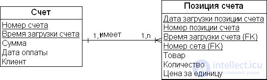
There is also a problem with conformed data marts. This type of global DW architecture represents a set of fact tables linked to one another via primary and foreign keys, in other words, a set of interrelated star schemas. Implementing a DW this way gives rise to a number of problems, such as isolated representation of subject-oriented areas, possible data redundancy, differences in how fact tables represent the level of structuring (granularity) of data, data synchronization during real-time loading, limited use of DM technology at the enterprise scale, and others. The star schema is a typical architecture that is designed and implemented using a "bottom-up" methodology, and conformed data marts are created based on a "bottom-up" approach but implemented based on a "top-down" approach.
One of the most difficult problems with conformed data marts is choosing the correct level of data granularity (grain) for fact tables. This means that aggregation of data across all tables must be consistent along the time dimension, and the structure of each fact table must not change in terms of adding new dimensions. This design approach limits the scalability and flexibility of the data model. Another problem can be auxiliary tables within dimensions that serve as references for relationships between dimensions. Granularity and stability of dimensions are important factors for successful DW design.
For example, if the granularity of the "Total Revenue" fact in the "Total Revenue" table (fig. 18.2) changes, this should result in duplication of the fact table with additional attributes added. Suppose that fact tables are linked to one another only through the same dimension keys. When a new dimension is added to one of the fact tables (for example, adding the "Contract" dimension to the "Total Revenue" fact table), the facts in the "Contract History" table must also change. Fact tables will remain unchanged only if they have the same granularity.
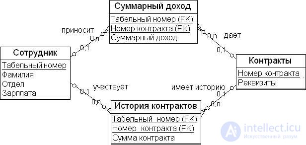
Among practicing DW developers there is a consensus that a DW architecture should be designed on a "top-down" basis while implementation is carried out on a "bottom-up" basis. This approach makes it possible to bring the architecture as close as possible to an understanding of the DW subject area's tasks, while implementation can incorporate fragments of the subject area into the overall DW in stages, without violating the mission and vision of the data warehousing system. Approaches to designing and developing DW architecture must be flexible enough to quickly adapt to growth in data volume and to expansion or change of subject areas within the system.
One approach to solving the problem of developing standard data models and architectures is a certain degree of normalization of data structures. Just as OLTP system database structures have a degree of normalization (1NF, 2NF, 3NF; 4NF, 5NF), DW databases should also have a certain degree of normalization of their data structure. The "Data Vault" model is one such normalized data structure for data warehouses. It includes methods for building data structures for many-to-many relationships, referential integrity, minimizing data duplication, and establishing semantic links between key business functions of a subject area through hubs.
The "Data Vault" design model, similar to multidimensional modeling or entity-relationship methods, contains a number of structural components, the new ones among which are hub entities, or hubs, link entities, and satellite entities. Design using this method focuses on the functional subject areas of an organization's activity. Each such area is characterized by a business key and is represented in the hub by a primary key. Link entities provide integration of operations between hubs. Satellite entities provide context for the hub's primary key. Each of these entities is constructed to provide maximum flexibility and scalability for the enterprise-scale DW data model.
Hub Entities. Hub entities, or simply hubs, are a table that contains a minimal list of business keys (natural keys). These are keys that the organization uses in every day-to-day operation: for example, an account number, an employee ID, a customer number, a product number, and a vehicle number. If such a key is lost in the course of business activity, then, as a rule, both the reference to its context and the accompanying information are lost as well. In addition to natural keys (in fig. 18.3, the "Customer Number in Source System" attribute), hubs can have the following attributes:
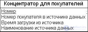
Fig. 18.3 shows an example of the "Customer Hub" entity. In this entity the "Customer Number in Source System" attribute is the primary business key, while the "Number" attribute is the surrogate key assigned to customers within the system. Table 18.1 shows an example of the context for the "Customer Hub" entity.
| Number | Customer Number in Source System | Load Time from Source | Data Source Name |
|---|---|---|---|
| 1 | 1234 | 23.01.2009 | Sales |
| 2 | 1235 | 24.01.2009 | Contracts |
| 3 | 2266 | 26.01.2009 | Finance |
| 4 | 2344 | 28.01.2009 | Sales |
Hub entities cannot be connected by a one-to-many (parent-child) relationship. Link entities are used to build relationships between hubs.
Link Entity. Link entities are the physical representation of a many-to-many relationship in 3NF. A link represents a relationship or an operation between two or more business components or business keys. Link entities contain the following attributes (see fig. 18.4):
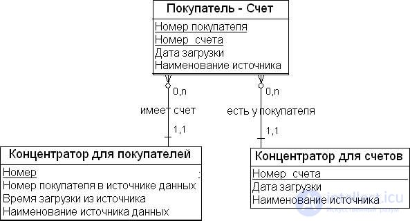
This model component is designed to resolve the many-to-many relationship problem for a DW. Together with hub entities, link entities describe the data flow of the DW subject area. Table 18.2 illustrates the contents of the database tables corresponding to these entities.
| Customer Hub | |||
|---|---|---|---|
| Number | Customer Number in Source System | Load Time from Source | Data Source Name |
| 1 | 1234 | 23.01.2009 | Sales |
| 2 | 1235 | 24.01.2009 | Contracts |
| Link Entity | |||
| Customer ID | Account ID | Load Time from Source | Data Source Name |
| 1 | 100 | 25.01.2009 | Sales |
| 2 | 200 | 26.01.2009 | Contracts |
| Account Hub | |||
| Number | Account Number in Source System | Load Time from Source | Data Source Name |
| 100 | 12/124 | 25.01.2009 | Sales |
| 200 | 12/135 | 26.01.2009 |
Contracts
|
The next model component is responsible for context, namely for answering the questions of when, why, what, where, and who creates operations and business keys (the 5W methodology). For example, knowing a vehicle's number is not, by itself, a reason for a customer to buy it. The customer needs to know the color, make, and so on. Satellite entities exist to store such information.
Satellite Entities. Satellite entities contain descriptive information about hub keys, namely when, why, what, where, and who creates operations and business keys. For example, unlike a vehicle number, its color, make, and so on can change over time, and therefore the data structure must reflect these changes at every level of information structuring (granularity).
Satellite entities usually contain the following attributes:
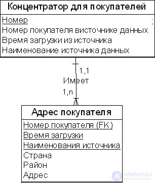
Fig. 18.5 shows a satellite entity containing information about changes in a customer's address over time. The "Load Time" attribute is part of the composite primary key. Since the data is ordered by time, the main purpose of the satellite entity is to provide a description of the hub key. Table 12.3 illustrates the contents of the database tables corresponding to these entities.
| Customer Hub | |||
|---|---|---|---|
| Number | Customer Number in Source System | Load Time from Source | Data Source Name |
| 1 | 1234 | 23.01.2009 | Sales |
| 2 | 1235 | 24.01.2009 | Contracts |
| Customer Address Satellite | |||
| Customer Number | Load Time | Source Name | Address |
| 1 | 23.01.2009 | Passport | 1 First St., Apt. 1 |
| 1 | 15.03.2009 | Passport | 6 Institutsky Ave., Apt. 3 |
| 2 | 24.01.2009 | Passport | 3 Second St., Apt. 2 |
| 2 | 14.02.2009 | Passport | 2 Communal St., Apt. 4. |
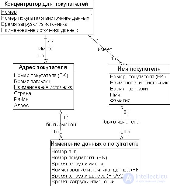
The "Point-In-Time" entity is derived from a satellite. It is built to support information lookup for given points in time. An example of a "Point-In-Time" entity is shown in fig. 18.6 below. Table 18.4 illustrates the contents of the database tables corresponding to these entities (the table structure is simplified for clarity).
| Customer Data Change | |||
|---|---|---|---|
| Customer Number | Change Load Time | Address Load Time | Name Load Time |
| 1 | 23.01.2009 | 23.01.2009 | 23.01.2009 |
| 1 | 15.03.2009 | 15.03.2009 | 15.03.2009 |
| 1 | 31.04.2009 | 31.04.2009 | 15.03.2009 |
| Customer Hub | |||
| Number | Customer Number in Source System | Load Time from Source | Data Source Name |
| 1 | 1234 | 23.01.2009 | Sales |
| Customer Address Satellite | |||
| Customer Number | Load Time | Source Name | Address |
| 1 | 23.01.2009 | Passport | 1 First St., Apt. 1 |
| 1 | 15.03.2009 | Passport | 6 Institutsky Ave., Apt. 3 |
| Customer Name Satellite | |||
| Customer Number | Load Time | Source Name | Last Name |
| 1 | 23.01.2009 | Passport | Prokhorov |
The "Point-In-Time" entity is derived from a satellite. It is built to support information lookup for given points in time.
The Bridge entity contains timestamps of the last load. This entity is similar to the "Point-In-Time" entity, but it spans the entire subject area or data schema.
Business users often want to see data grouped in different ways. In the simplest case, one department (say, marketing) has its own customer hierarchy, while another department (say, sales) has a different hierarchy of the same customers. Both hierarchies could be included in the "Customer" dimension. However, several hierarchies built directly into a dimension would make it unwieldy to use.
The business requirement for a more flexible implementation of additional hierarchies arises when several departments need to group the same data by different classification schemes, and moreover in several different variants. In such a case it is necessary to work with users and determine the most common data grouping. This grouping becomes the standard, default hierarchy and is built directly into the main dimension table. The same can be done for a few of the other most widely used hierarchies for ease of use by users.
To support additional hierarchies, a separate table is created in the DW that allows the user to group data by any of the available hierarchies. This is the bridge entity, or bridge table. Fig. 18.7 shows an example of such an intermediate table, "Customer Geographic Location" (CustomerRegionHierarchy), for grouping by geographic location.
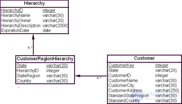
In a query, the value of the "Hierarchy Name" field ( HierarchyName ) specifies the required data grouping. For example, the predicate in the clause WHERE HierarchyName = 'Отдел маркетинга' specifies a data grouping for the marketing department.
Every hierarchy in the intermediate table must be complete, i.e., it must start at the level of the base dimension to which the intermediate table is attached and end at the topmost level. For example, the "Customer Geographic Location" table (CustomerRegionHierarchy) is connected at the "State" level.
To simplify analysis and reporting, the intermediate table should also contain a description of the standard hierarchy. The standard hierarchy becomes the default used in all pre-configured reports, but the user is given the option to switch to a different hierarchy. A separate "Hierarchy" table with one row per hierarchy simplifies system maintenance but visually complicates the design. If needed, denormalization can be performed by merging the "Hierarchy" table with the "Customer Geographic Location" (CustomerRegionHierarchy) table.
User Grouping Link entity contains information that provides the user with a particular point of view on the data, but does not affect the content of the data in the DW. Table 18.5 shows how the user grouping link entity is used.
| "Customer Groups" dimension table | |||
|---|---|---|---|
| ID | Group Label | Load Date | Source Description |
| 1 | Major customers | 10.04.2009 | Excel |
| 2 | Minor customers | 12.04.2009 | Excel |
| User Grouping Link Entities | |||
| Group Number | Customer Number | Load Date | Source Description |
| 1 | 100 | 14.04.2009 | Excel |
| 2 | 101 | 14.02.2009 | Excel |
| ID | Customer Number | Load Date | Source Description |
| 100 | 100ADB12 | 14.04.2009 | Finance |
| 101 | ADF-1 | 14.04.2009 | Finance |
Thus, the user grouping link entity makes it possible to establish how users will unfold the data in fact tables.
We have examined the main and additional elements of the "Data Vault" model and can now move on to describing the general algorithm for building a DW model using the method described above.
When creating a "Data Vault" model, it is necessary first to create the entities and describe their attributes, and then to establish the relationships between them. Entities should be created in the following order.
When creating relationships in the "Data Vault" model structure, the rules of referential integrity must be observed.
Data changes are collected in satellites. If a satellite's size grows very quickly, two new satellites can be created to limit this growth. Data in the new satellites can be separated by type of information or by rate of change.
Hubs store the business keys of the organization's main lines of activity (subject areas). Business keys typically change very rarely. A hub's primary key is used in link entities to represent operations of the main lines of activity.
Now let us consider applying the above algorithm to a tutorial example, i.e., let us build a "Data Vault" model for the tutorial example's schema.
Let us consider the Northwind database, developed by Microsoft for training purposes. Its data model is shown in fig. 18.8.
As can be seen from the figure, this model is characterized by the use of nonstandard data types: bit, ntext, image, money. Using nonstandard data types can lead to data conversion problems if a different DBMS is used to build the DW than the one used in the OLTP system. In our case, the "Data Vault" will be built on the same DBMS as the OLTP system, namely Microsoft's MS SQL Server 2008.
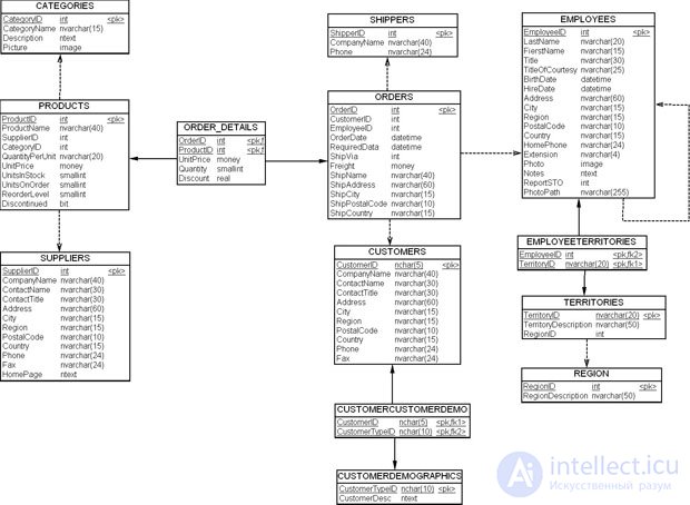
Let us examine the process of converting the normalized model from the example (fig. 18.7) into a "Data Vault" model. As discussed in previous sections, the conversion process includes the following stages.
Let us note right away that for the tutorial example's model, adding bridge entities and "Point-In-Time" entities is not required.
When working with more than one data model (integrating several data sources), the conversion should begin with the model that is the primary one from the standpoint of the organization's system's lines of activity, and then proceed in stages to the models of other subsystems, in order to arrive at a unified point of view on data representation in the system's model as a whole.
Now let us proceed to implementing steps 1-3 of the process of forming a "Data Vault" model for the tutorial example.
Let us follow the process we have described for building a "Data Vault" model. First we identify the business keys and place them in standard-structure hub entities. Since hubs are, by definition, a list of business keys, it is important to place them together with surrogate keys, if such exist in the model.
By examining the model in fig. 18.8 (unique indexes, data queries, etc.), we can build the following groups of business keys/surrogate keys and identify the entities that are candidates for the role of hubs in the "Data Vault" model.
The "Categories" table ( Categories ) has the business key "Category Name" ( CategoryName ) and the surrogate key "Category ID" ( CategoryID ). These will be the constituent elements of the "Category Hub" hub entity ( HUB_Category ).
The "Products" table ( Products ) has the business key "Product Name" ( ProductName ) and the surrogate key "Product ID" ( ProductID ). These will be the constituent elements of the "Product Hub" hub entity ( HUB_Product ).
The "Suppliers" table ( Suppliers ) has the business key "Supplier Name" ( SupplierName ) and the surrogate key "Supplier Identifier" ( SupplierID ). They will become the components of the hub entity "Hub_Supplier" ( HUB_Supplier ).
The "Order Details" table ( Order Details ) has no business key, does not represent a business process, and therefore cannot have its own hub.
The "Orders" table ( Orders ) has a surrogate key, which may or may not be tied to a business key, depending on the business requirements. This table is transactional in nature and is a better candidate for a link entity than for a hub.
The "Shippers" table ( Shippers ) has the business key "Company Name" ( CompanyName ) and the surrogate key "Shipper Identifier" ( ShipperID ). They will become the components of the hub entity "Hub_Shipper" ( HUB_Shippers ). Note that if the business requirements call for integrating shipping companies, the "Company Name" ( CompanyName ) field can be used as the business key. However, if the business requirements call for shippers to be maintained separately from one another in the system, that field is not descriptive enough for the business process and should be replaced with the "Shipper Name" field ( ShipperName ).
The "Customers" table ( Customers ) has the business key "Company Name" ( CompanyName ) and the surrogate key "Customer Identifier" ( CustomerID ). They will become the components of the hub entity "Hub_Customers" ( HUB_Customers ). Note that if integrating customers and shippers is needed, the hub could be named "Hub_Company" ( HUB_Company ) so as to integrate shippers and customers together.
The "Customer_Customer" table ( CustomerCustomerDemo ) has no business key and therefore cannot be converted into a hub. This table is a candidate for a link entity.
The "Customer Demographics" table ( CustomerDemographics ), at first glance, has the business key CustomerDesc and the surrogate key CustomerTypeID, and a hub "Hub_CustomerDemographics" ( HUB_CustomerDemographics ) could be created for it. However, note that this table could also be treated as a satellite entity for customers.
The "Employees" table ( Employees ) has the business key "Employee Name" ( EmployeeName ) and the surrogate key "Employee Identifier" ( EmployeeID ). They will become the components of the hub entity "Hub_Employee" ( HUB_Employee ).
The "Employee Territories" table ( EmployeeTerritories ) has no business key and therefore cannot be converted into a hub. This table is a candidate for a link entity.
The "Territories" table ( Territories ) has the business key "Territory Description" ( TerritoryDescription ) and the surrogate key "Territory Identifier" ( TerritoryID ). They will become the components of the hub entity "Hub_Territory" ( HUB_Territories ).
The "Region" table ( Region ) has the business key "Region Description" ( RegionDescription ) and the surrogate key "Region Identifier" ( RegionID ). They will become the components of the hub entity "Hub_Region" ( HUB_Region ).
We can now compile the list of hub entities of the model that need to be built (Fig. 18.9).
| "Hub_Category" | Hub_Categories |
| "Hub_Product" | Hub_Producst |
| "Hub_Supplier" | Hub_Suppliers |
| "Hub_Shipper" | Hub_Shippers |
| "Hub_Company" | Hub_Customers |
| "Hub_CustomerDemographics" | Hub_CustomerDemographics |
| "Hub_Employee" | Hub_Employees |
| "Hub_Territory" | Hub_Territories |
| "Hub_Region" | Hub_Region |
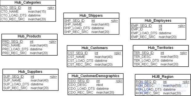
To denote business keys we will use different names than those in the diagram in Fig. 18.8.
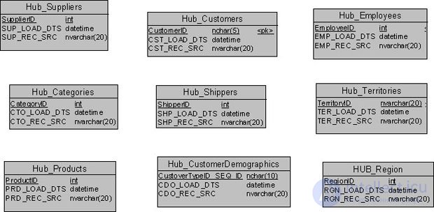
Let us look at the list of hubs in Fig. 18.9. Note that the surrogate keys in the diagram in Fig. 18.8 uniquely determine the business keys of the corresponding tables. Consequently, we can replace the business keys in the hubs with their corresponding surrogate keys. It makes sense to do this because the size of a surrogate key is, as a rule, considerably smaller than the size of the corresponding business key. For instance, the type of the surrogate key "Category Identifier" ( CategoryID ) is int, which takes up 2 bytes, as opposed to the 16 bytes of the business key "Category Name" (CategoryName) (the CTO_NAME field in the hub). This is standard practice in data warehouse design.
Fig. 18.10 shows the final list of hub entities for the tutorial example model.
The hub table for a hub entity is created with the CREATE TABLE command, as shown below for the "Hub_Categories" hub ( Hub_Categories ). The remaining hubs of the model are created in the database in the same way.
CREATE TABLE Hub_Categories (
    CategoryID int NOT NULL,
    CTO_LOAD_DTS datatime NOT NULL,
    CTO_REC_SRC nvarchar(20) NOT NULL,
PRIMARY KEY (CTO_SEQ_ID)
);
CREATE UNIQUE INDEX Hub_Categories_idx
ON Hub_Categories (CategoryID);
We can now move on to building the link entities for the "Data Vault" model of the tutorial example.
In the second stage of converting the source model into a "Data Vault", it is necessary to identify the link entities, i.e., the relationships between business keys. Link entities represent the organization's business processes; their purpose is to connect business keys with one another. They are the most important elements of a data warehouse in the "Data Vault" model — without them it is difficult to relate data to one another. Transactional tables and tables used to resolve many-to-many relationships are good candidates for link entities.
For the tutorial example model, the following link entities can be identified.
The "Order Details" table ( OrderDetails ) is in a many-to-many relationship, and therefore a link entity "Link_OrderDetails" ( LNK_OrderDetails ) will be built for it.
The "Orders" table ( Orders ) is the parent table for the "Order Details" table OrderDetails, so a link entity "Link_Orders" ( LNK_Orders ) will be built for it.
The "Customer Customer" table ( CustomerCustomerDemo ) is in a many-to-many relationship, and therefore a link entity "Link_Customer_Customer" ( LNK_CustomerCustomerDemo ) will be built for it.
The "Employee Territory" table ( EmployeeTerritories ) is in a many-to-many relationship, and therefore a link entity "Link_Employee_Territory" ( LNK_EmployeeTerritories ) will be built for it.
The "Territory" table ( Territories ) is in a many-to-many relationship, and therefore a link entity "Link_Territory" ( LNK_Territories ) will be built for it.
Let us continue examining the tutorial example model. It is easy to notice that some tables that are candidates for hub entities are in a parent-child relationship with respect to a foreign key. For the "Products" table ( Products ), these are the "Category Identifier" ( CategoryID ) and "Supplier Identifier" ( SupplierID ) keys. It therefore makes sense to build a link-entity table LNK_Products that includes "Product Identifier" ( ProductID ), "Supplier Identifier" ( SupplierID ), and "Category Identifier" ( CategoryID ). Note that this table does not require a surrogate key, since "Product Identifier" ( ProductID ) is sufficient to represent suppliers and categories.
The "Employees" table ( Employees ) has a recursive relationship. To represent it, we introduce the link-entity table "Link_Employees" ( LNK_ Employees ).
There are no other relationships in the tutorial example model that can be extracted into link entities. We can now combine the hub entities and the link entities in the model diagram, as shown in Fig. 18.11.
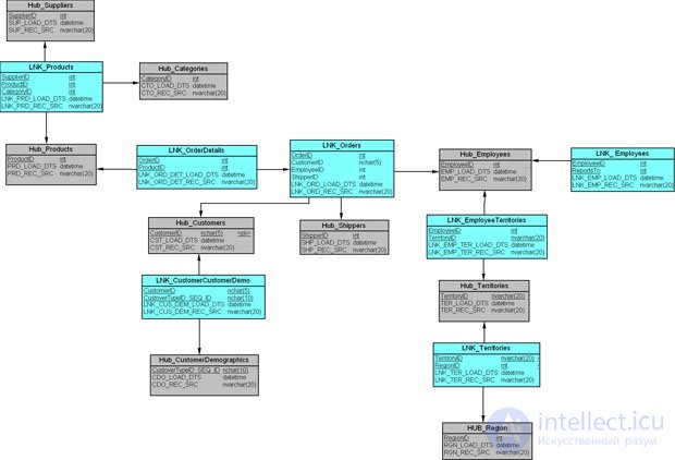
The database table for a link entity is created with the CREATE TABLE command, as shown below for the "Link_Products" link ( LNK_Products ). The remaining link entities of the model are created in the database in the same way.
CREATE TABLE LNK_Products (
ProductID int NOT NULL,
CategoryID int NOT NULL,
SupplierID int NOT NULL,
CTO_LOAD_DTS datatime NOT NULL,
CTO_REC_SRC nvarchar(20) NOT NULL,
PRIMARY KEY (ProductID),
FOREING KEY(SupplierID) REFERENCES HUB_Suppliers,
FOREING KEY(CategeoryID) REFERENCES HUB_Categories
);
Having built the hub entities and the link entities, we can move on to building the satellite entities for the "Data Vault" model of the tutorial example.
The remaining fields of the tables in the diagram in Fig. 18.8 are instances of entities that change over time and will therefore be placed in satellite entities. In the model under consideration, the following tables can serve as satellite entities:
| the "Categories" table (Categories) | satellite entity CAT_CATEGORIES ; |
| the "Products" table (Products) | satellite entity CAT_PRODUCTS ; |
| the "Suppliers" table (Suppliers) | satellite entity CAT_SUPPLIERS ; |
| the "Orders" table (Orders) | satellite entity CAT_ORDERS ; |
| the "Customers" table (Customers) | satellite entity CAT_CUSTOMERS ; |
| the "Shippers" table (Shippers) | satellite entity CAT_SHIPPERS ; |
| the "Employees" table (Employees) | satellite entity SAT_EMPLOYEES ; |
| the "Territories" table (Territories) | satellite entity SAT_TERRITORIES ; |
| the "Region" table (Region) | satellite entity SAT_REGION ; |
| the "Customer Demographics" table (CustomerDemographics) | satellite entity SAT_CUSTOMERDEMOGRAPHICS. |
Note that satellite entities do not contain attributes that depend on a foreign key. The primary key of a satellite entity is a composite key: the primary key of the corresponding hub entity plus the data load time.
We can now combine the satellite entities with the hub entities and link entities in the model diagram, as shown in Fig. 18.12.
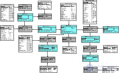
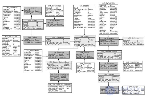
The database table for a satellite entity is created with the CREATE TABLE command, as shown below for the "Satellite_Products" satellite ( CAT_Products ). The remaining satellite entities of the model are created in the database in the same way.
CREATE TABLE SAT_Products (
ProductID int NOT NULL,
PRD_LOAD_DTS DateTime NOT NULL,
QuantityPerUnit nvarchar(20),
UnitPrice money,
UnitsInStock smallint,
UnitsOnOrder smallint,
ReOrderLevel smallint,
Discontinued bit,
PRD_REC_SRC nvarchar(20) NOT NULL,
PRIMARY KEY (ProductID, PRD_LOAD_DTS)
FOREING KEY (ProductID) REFERENCES HUB_Products
);
This completes the construction of the "Data Vault" model for the data schema of the tutorial example.
We can now move on to discussing how to populate the objects of the resulting physical model.
In practice, it is advisable to use virtual tables, or views, one for each object of the model, to populate the "Data Vault" objects.
Data is only ever inserted into hub entities: business keys are added when the data warehouse is initially populated. Link entities are populated in a similar way. Data is inserted into satellite entities whenever data changes occur in the source systems.
When loading a hub entity, only those business keys (together with their surrogate keys) that are not yet in the hub are selected. To implement this process, the view shown below can be used, using the "Hub_Categories" hub as an example.
CREATE VIEW V_INS_HUB_CATEGORIES AS

SELECT DISTINCT
A.CATEGORYID,
GETDATE() LOAD_DATE,
'NORTHWIND' RECORD_SOURCE
FROM NORTHWIND..[CATEGORIES] A with (NOLOCK)
WHERE NOT EXISTS
(SELECT * FROM HUB_CATEGORIES WITH (NOLOCK))
When loading a link entity, only those composite keys (together with their surrogate keys) that are not yet in the link are selected. To implement this process, the view shown below can be used, using the "Link_Orders" link as an example.
CREATE VIEW V_INS_LNK_ORDERS AS
SELECT DISTINCT
A.ORDERID,
A.CUSTOMERID,
A.EMPLOYEEID,
A.SHIPVIA,
GETDATE() LOAD_DATE,
'NORTHWIND' RECORD_SOURCE
FROM NORTHWIND..[ORDERS] A with (NOLOCK)
WHERE NOT EXISTS
(SELECT * FROM LNK_ORDERS WITH (NOLOCK))
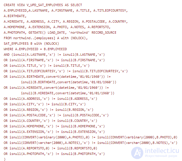
When loading a satellite entity, the set of records matching or joined by the business key (or the composite key) whose columns have changed in the source tables for the satellite is selected, and only the most recent changes are taken. To implement this process, the view shown below can be used, using the "Satellite_Employees" satellite as an example.
Views work well when the source database and the "Data Vault" are entities of the same relational database. If this is not the case, two solutions are possible: 1) using a staging area for the data source so that views can still be used; 2) using ETL tools to transform, compare, and load the data.
A "Data Vault" is a subject-oriented set of normalized tables that preserves history and unique relationships in the data, providing information support for one or more of an organization's lines of business.
A "Data Vault" has three main "building blocks".
In general terms, the algorithm for building a "Data Vault" consists of designing entities in the following order:
One of the main advantages of the "Data Vault" method is a dynamic representation of the relationships within the data warehouse's subject area. Relationships are defined through the business keys of the hubs and are recorded in the link entities. They exist over time, and their history is preserved in the satellites. This makes it possible to display the dynamics of how a relationship develops.
It makes sense to use the "Data Vault" method in the following cases:
Thus, we have covered yet another method for modeling data warehouses.

Comments