
Lecture
Cardiopulmonary bypass (CPB) is the temporary replacement of the gas-exchange function of the lungs and the pumping function of the heart by special devices for the period required to perform a cardiac surgical operation.
Improvement of myocardial contractility during mechanical circulatory support is achieved in two ways:
At present, the main technologies for treating severe forms of heart failure (SFHF) are based on:
Cardiopulmonary bypass is usually used in heart operations. This method allows the surgical team to oxygenate and maintain circulation of the patient's blood, which allows the surgeon to operate on the heart. In many operations, such as coronary artery bypass grafting (CABG), the heart is stopped (i.e. arrested) because of the complexity of operating on a beating heart. Operations that require opening the chambers of the heart, such as repair or replacement of the mitral valve, require the use of Cardiopulmonary bypass (CPB) to avoid systemic air entrainment and to provide a bloodless field for increased visibility for the surgeon. The machine pumps the blood and, using an oxygenator, allows the red blood cells to pick up oxygen while also reducing the level of carbon dioxide. This mimics the work of the heart and lungs, respectively.
MCS systems are used in three categories of patients.
The first group includes patients who,
after undergoing open-heart surgery,
cannot be weaned off the cardiopulmonary
bypass (CPB) machine (2–8% of patients). The duration of such support ranges from several
days to several weeks.
The second group includes patients with acute
damage to the heart muscle (myocardial infarction,
acute myocarditis, etc.). In this case, to overcome the period of the resulting critical heart
failure (HF), temporary hemodynamic support is required. The probability of the heart's normal function recovering after
a certain period of time, combined with intensive drug therapy, is quite
high.
The third group includes patients with chronic severe forms of heart failure.
The last group involves different approaches in determining the strategy for using MCS:
In accordance with this classification, methods and requirements were developed for systems
for short-term MCS (from several days
to a month – patients of the first and second groups,
although there are options for using short-term MCS for unplanned HT) and methods and
requirements for long-term MCS – patients of the third
group.
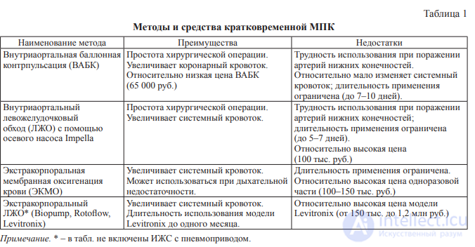
Table 1 presents the main methods and means for short-term MCS
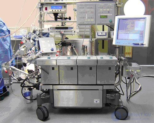
Structurally, the device is an assembly consisting of a console with pumps and a control unit with the necessary set of sensors and auxiliary equipment (infusion stands, stainless steel shelves, venous clamp). Roller pumps with a roller rotation speed of up to 250 rpm are mounted on the movable console, which makes it possible to obtain blood flows from 0 to 11.2 liters per minute through ½" tubing. One of the pumps (arterial) pumps blood from the venous system into the arterial system. The second — is intended for drainage of the left ventricle of the heart, the third — for suctioning blood from the wound and returning it to the extracorporeal circuit, the fourth and fifth pumps are used for various cardioplegia modes. To reduce the size of the device and ensure coordinated blood cardioplegia modes, the pumps can be combined into a single pump module with 2 independent motors in a single housing and with a shared electronic control module. In addition to the pumps, the device is equipped with a pressure monitoring unit, an electric thermometer, a gas mixer, timers, and level and bubble detectors — combined into a control unit.
Blood pumps are used of three types: those creating systole and diastole separately (based on the principle of changing the chamber volume by a membrane using a hydraulic or pneumatic medium); those creating blood flow in flexible tubes by expansion or compression (valves are placed in the lumen of the tube or outside it); those creating blood flow with an intermittent wave (roller and finger pumps). All blood pumps are divided by mechanism of action into pumps with constant and variable stroke volume, and by the nature of the blood flow they create into pumps with low and high pulsation. To implement temperature regimes, a heat exchanger with a temperature-control device is used. The control system provides the specified operating modes both for individual functional units and for the device as a whole.
The heart-lung machine is driven by a hydraulic, pneumatic, or electromechanical drive. In emergency mode, a manual drive is used. Many heart-lung machines for different purposes have been created worldwide: for isolated chemotherapy of malignant neoplasms, inflammatory processes and destructive lesions; for auxiliary circulatory support in cases of cardiac and respiratory dysfunction; for resuscitating patients in a state of clinical death; for maintaining the vital functions of isolated organs intended for subsequent transplantation. All devices have a common structural design and differ from one another in performance, features of their control systems, or additional special functional units.
Blood pumps are used of 3 types: 1) those creating systole and diastole separately; based on the principle of changing the chamber volume by a membrane using a hydraulic or pneumatic medium; 2) those creating blood flow in flexible tubes by expansion or compression; the valves in these pumps are placed in the lumen of the tube or outside it; and 3) those creating blood flow with an intermittent wave (roller and finger pumps). All blood pumps are divided by mechanism of action into pumps with constant and variable stroke volume, and by the nature of the blood flow they create into pumps with low and high pulsation. To implement temperature regimes corresponding to the purpose of the operation, i.e. to perform cardiopulmonary bypass under conditions of normal or reduced temperature, a heat exchanger with a temperature-control device is used. The control system provides the specified operating modes both for individual functional units and for the device as a whole. The AIK is driven by a hydraulic, pneumatic, or electromechanical drive. In emergency mode, a manual drive is used.
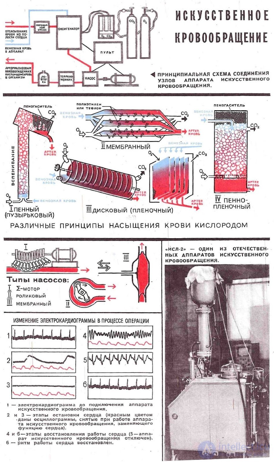
More than 100 types of AIK for various purposes have been created worldwide: for isolated chemotherapy of malignant neoplasms, inflammatory processes and destructive lesions; for so-called auxiliary circulatory support in severe cardiac and respiratory dysfunction; for reviving patients and casualties in a state of clinical death; for maintaining the vital functions of isolated organs intended for subsequent transplantation, etc. All devices have a common structural design (Fig. 1) and differ from one another in performance, features of their control systems, or the inclusion of additional special functional units. The schemes for connecting the AIK to the patient's vascular system depend on the chosen variant of cardiopulmonary bypass. Among the AIK for cardiac surgery, common models are those in which the «artificial heart» is represented by roller pumps, and the «artificial lungs» — by a disc oxygenator [devices «Pemco», «Sarens», «Imico» (USA), ISL-4, ASP-2 (USSR)]. In the Soviet devices for this purpose, the AIK-5 (Fig. 2) and AIK-5M, the physiological unit consists of membrane pumps and a foam-film oxygenator.
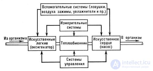
Fig. 1. Block diagram of the heart-lung machine.
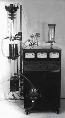
Fig. 2. Heart-lung machine AIK-5 for cardiac surgery use.
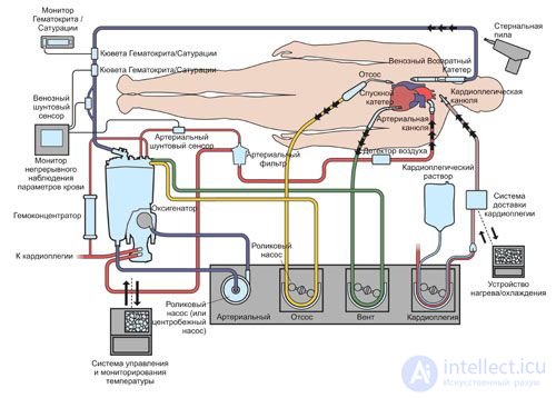
Operating principle
The heart-lung machine temporarily replaces the function of the heart and lungs. Therefore, it consists of several units, namely:
The scheme and technique for connecting the AIK may vary depending on the surgical approach and the type of cardiac (or vascular) pathology. For pumping blood, one of the femoral or iliac arteries is more often used, from which blood flows retrogradely into the abdominal and thoracic aorta, then into its arch, passing into the vessels supplying the brain and heart (coronary vessels). Sometimes arterialized blood is pumped through a cannula into the ascending aorta. Drainage of the venous system is performed either with two plastic catheters inserted into both venae cavae through the right atrium, or with a single catheter inserted into the right atrium or ventricle. Venous blood enters the AIK oxygenator, where it is saturated with oxygen, and is directed by the AIK pump into the patient's arterial system. Both of these manipulations are performed after heparin is introduced into the patient's blood at a dose of 2—3 mg per 1 kg of body weight. For greater patient safety, cannulation of the arterial system should precede catheterization of the venous bed.
Extracorporeal circulation is started by simultaneously switching on the arterial pump and releasing the clamps on the venous line of the apparatus, without allowing complete drainage of blood from the body. By synchronously increasing the pump output and the venous return, the perfusion flow rate is brought up to the calculated value (2.2—2.4 L/min per 1 m² of body surface area). Thereafter, the criteria for adequacy of perfusion are followed.
The duration of extracorporeal circulation depends on the nature of the pathology and ranges from several minutes (closure of an atrial septal defect, elimination of isolated valvular stenosis of the pulmonary trunk) to many hours (simultaneous replacement of several heart valves) .
The transition to natural circulation begins with a gradual or one-step cessation of blood flow into the apparatus, together with a simultaneous decrease in the output of the arterial pump. Pumping of blood into the arteries is stopped completely once the optimal volume of circulating blood has been reached in the patient's vascular bed, which is judged by the central venous pressure, which at this point should be 150—180 mm of water column.
In the case of prolonged extracorporeal circulation (over 1 hour), it is advisable to combine it with artificial hypothermia, which is accompanied by a decrease in the body's oxygen demand, allowing the perfusion flow rate to be reduced and thereby reducing trauma to the formed elements of the blood. In most cases moderate hypothermia (esophageal temperature not below 28°) is sufficient. Deep hypothermia down to 15—10° is used extremely rarely, when temporary complete circulatory arrest is required.
During extracorporeal circulation, the method of controlled hemodilution is widely used, that is, dilution of the circulating blood with replacement fluids (for example, low-molecular-weight solutions of electrolytes, sugars or proteins) .
This apparatus was not yet ready for clinical trials on humans, since its use caused massive traumatization of blood cells.
Let us consider modern extracorporeal circulation apparatuses.
Their purpose is the temporary replacement of the functions of the heart and lungs. A heart-lung machine (AIK) has two main units:
Basic requirements for extracorporeal circulation apparatuses:
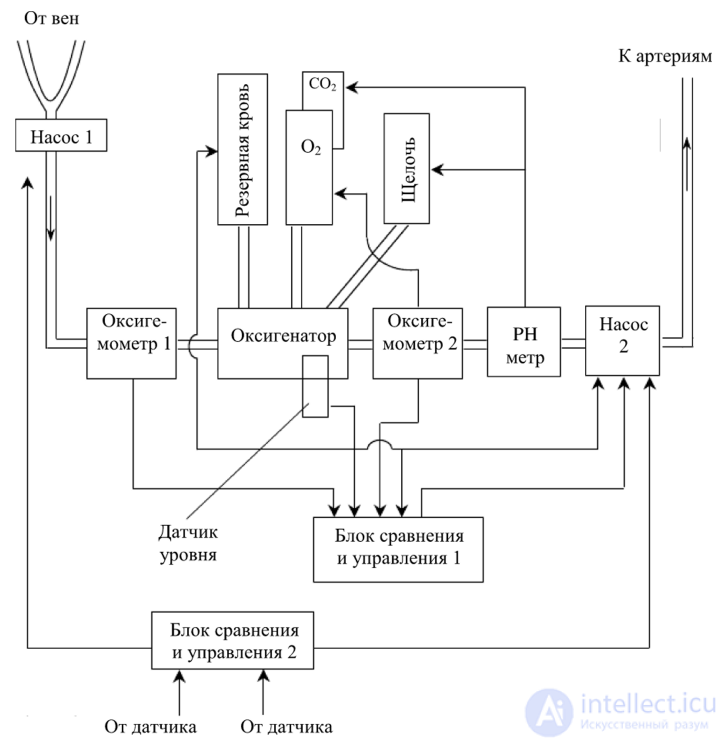
Fig. 143 shows the general diagram of the AIK.
venous arterial
pressure pressure
Fig. 143. Diagram of the AIK
The AIK additionally includes:
The AIK operates as follows. Blood taken from the veins passes through pump 1 (Fig. 143), which regulates the rate of blood delivery to the oxygenator, before which the amount of O2 in the venous blood is measured by oximeter 1. The oxygenator saturates the blood with O2 by controlling the O2 source, which is regulated from comparison and control unit 1, receiving information from oximeter 2. The blood then passes to pump 2, where the pH of the blood is measured, and when the alkali level in the blood decreases it is added to the oxygenator, while when acidity decreases CO2 is supplied to the oxygenator. The blood then passes through pump 2 to the patient's arteries. During this, the pressure in the venous and arterial beds is continuously measured by pressure sensors, and through comparison and control unit 2 control signals are sent to pumps 1 and 2, by means of which the required pressure in the patient's blood supply system is achieved.
Today there are more than 30 designs of AIK, of which the most widely used are the AIK:
Problems of cleaning the apparatus. Special attention is given to the blood path through the apparatus; before the operation it is washed with soda and soap.
Boiling and autoclaving the AIK and its parts. Before use, 1 L of alcohol is first run through the AIK system, then 1.5...2 L of saline is run through, and all these solutions are passed through the apparatus's paths for 20.. .30 min.
Donor blood (about 500 g) is used; it is poured into the oxygenator.
It should additionally be noted that, in the course of use in resuscitation medical technologies, as well as for intensive care, auxiliary circulation apparatuses are used when the heart is functioning weakly. At the same time, treatment of the underlying disease causing the heart weakness is carried out in parallel, in cases of major blood loss, poisoning, or infectious diseases.
Next let us consider examples of AIK designs.
MAQUET HL-30 extracorporeal circulation apparatuses
The MAQUET AIK (Fig. 144) embodies a completely new concept in the design and functionality of extracorporeal circulation apparatuses. On the one hand, the system meets the requirements of today's and future perfusion methods, while on the other hand it represents, from a technical standpoint, a perfect combination of clear functional design, maximum flexibility, advanced technology and reliability.
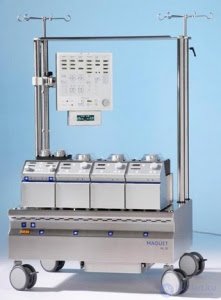
Fig. 144. MAQUET HL-30 AIK
MAQUET represents the latest generation of extracorporeal circulation apparatuses. Perfusiologists have always felt the need for a flexible, ergonomic system equipped with advanced technology that at the same time remains reliable and convenient to work with.
The HL-30 extracorporeal circulation apparatus can be configured to provide comfortable working conditions for any user: short or tall, right-handed or left-handed, preferring to work sitting or standing - none of this matters. The key factor is individual adjustment to achieve maximum flexibility and optimal ergonomics.
The basis of the system is a stable, compact console with stands, by means of which monitors, pumps and other equipment can be mounted on height-adjustable swivel brackets of various lengths, which are set up according to individual needs. This makes it possible to place all devices in positions that are optimal for the user.
The HL-30 AIK system gives perfusiologists the ability to place pumps, the oxygenator and tubing in the most convenient positions close to the patient. As a result, the length of the supply tubing is significantly reduced and priming volumes are minimized. New equipment can be added to the existing system or the system can be reconfigured at any time.
The artificial heart (Fig. 145), or artificial ventricles, is used in patients in the terminal stage of heart failure to save their lives and support circulation until a suitable donor heart is found for transplantation.
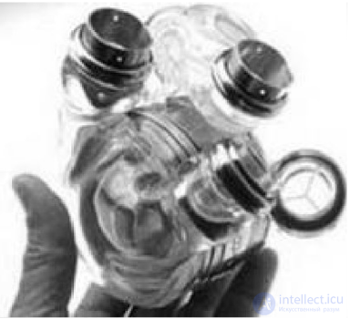
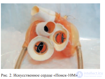
Fig. 145. Artificial heart
Pumps of various designs (piston, balloon, membrane, rotary) are placed in the chest cavity or located outside the body and connected to the diseased heart by catheters. Some of them take over the functions of the entire heart, others only of a single ventricle.
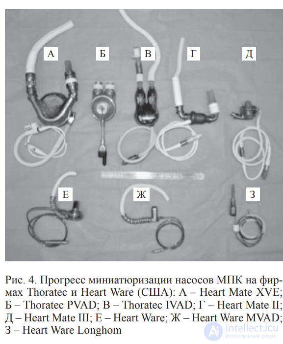
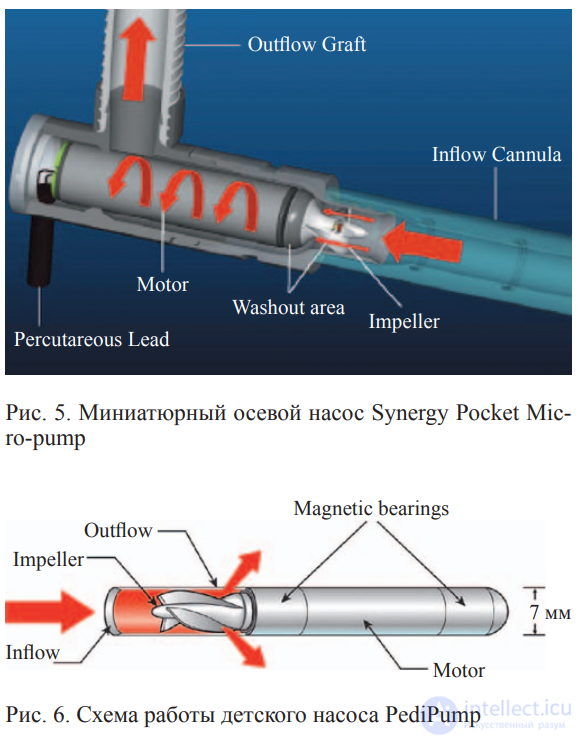
The very first operation to implant an artificial heart, performed on a 58-year-old man, ended in failure.
The American company Abiomed was the first to develop a permanent artificial heart. It could help patients for whom treatment of their own heart or implantation of a donor heart is impossible. The development was tested and refined over several years on a number of volunteers.
A portable artificial heart, created on new operating principles in 2007 by a group of specialists headed by Professor Andy Tan of the Institute of Biomedical Innovation (Australia) (Fig. 146), belongs to the so-called biventricular assist devices. This means that the new pump supports both the right and left halves of the diseased heart simultaneously. A common problem with such devices is their size, since in effect two separate pumps have to be fitted into the chest cavity.
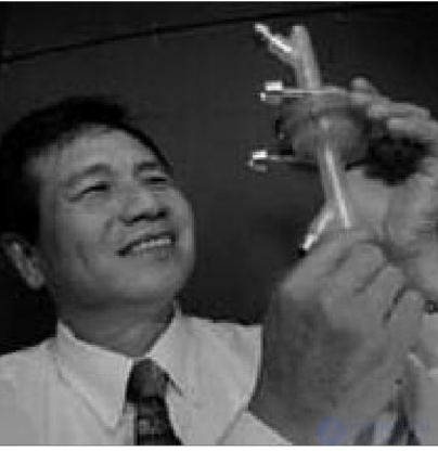
Fig. 146. Portable artificial heart
The new so-called «counter-flow pump», created
by A. Tan, combines both functions in a single mechanism for the first time. It has two impellers that drive the blood and rotate as a single unit. This ensures the correct pressure in each half of the heart.
A. Tan notes that in patients who were implanted with an artificial left ventricle (such «half» assist devices are still more common), the risk of death over the following year was reduced by 47%. So a mechanical assist heart serving both halves of the natural blood pump will further increase patients' chances of survival.
The «Artificial Heart» apparatus is designed to collect blood from the surgical wound and reinfuse it, and makes it possible to perform operations in general surgery, traumatology and orthopedics, gynecology, vascular surgery, and emergency surgery without transfusion of donor blood. The use of the apparatus makes it possible to rule out complications associated with the transfusion of donor blood (antigenic incompatibility, post-transfusion complications, infection with hepatitis, AIDS).
In the first models of artificial heart (AH) apparatuses, little attention was paid to automatic control. The main issues addressed were the creation of an optimal design, the search for hemocompatible materials, and the development of compact, reliable drives. In addition, the lack of quantitatively generalized, comprehensive data on the properties and characteristics of the cardiovascular system and on the regulation of cardiac output also made it difficult to choose an optimal control strategy for the AH.
At the same time, in building AH control systems researchers encounter methodological difficulties in achieving reliable, continuous measurement of the body's parameters. For this reason, control systems with manual adjustment of the pump's operating mode based on individual central hemodynamic parameters are most often used.
At present, practically all research centers in the world working on the development of the AH have begun research into the creation of automatic control systems. In this connection, four directions can be distinguished in the development of AH control systems.
1. Development of control systems based on the limited and specific initial information available to researchers. Usually, in this case, the source of information is a sensor for one of the variables in the AH. Since such a sensor is one of the links in a closed-loop AH control system (with an operator involved, or in a fully automated system), the possibilities for obtaining initial information largely determine the principles used to build the control systems. Most often, a capacitive sensor of the position of the blood pump's diaphragm is used. Its main purpose is to obtain primary information on pump output.
2. The second direction is based on a purely mechanical replacement of manual control elements with automatic regulators. In this case, the control algorithm is chosen empirically, based on expert assessments of the work of operators controlling the AH in an experiment. An example of this direction is the first version of the modernization of the «Vitamek» apparatus for AH control.
3. The third direction – building control systems based on studying the dynamics of the main physiological variables in the circulatory system. Practically all systems for stabilizing one or another variable are built on this principle, for example the blood pressure in the atria or in the aortic reservoir.
It is known that there is no pressure stabilization loop for atrial pressure in the body. However, within the range of physiological conditions this pressure varies within insignificant limits, which has allowed some researchers to use a servo-control loop that stabilizes the atrial pressure. Because of the peculiarities of the long-term operation of the AH in the circulatory system, the use of such parameters for control is associated with both methodological and technical difficulties, which make the operation of the apparatuses unreliable and imprecise.
4. The fourth direction in AH control – studying the mechanisms regulating cardiac output and reproducing the main regulatory characteristics of the heart. This direction is the most complex, since to date there is not enough complete quantitative information in the physiology of the heart and circulation on the interaction of regulatory processes that are significantly linked to the circulatory system. This direction presupposes a deep understanding of the processes regulating cardiac output, knowledge of the quantitative relationships and patterns in these processes, and the construction of corresponding models on which one or another AH control algorithm can be worked out.
At present, in AH control the most widespread algorithms are those based on reproducing the Frank-Starling mechanism. This mechanism is considered the main algorithm for regulating the natural heart, although it is also subject to the influence of numerous nervous and humoral control channels.
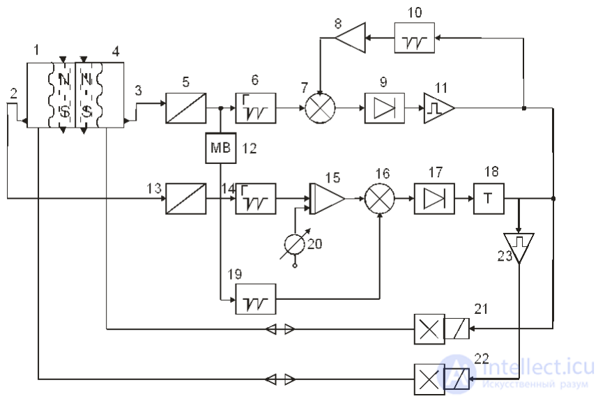
Fig. 7.7 shows a block diagram of the control system for the duration of the ejection phase as a function of the rate of ventricular filling. Let us consider the operation of the left control channel.
 =
=
Fig. 7.7 – Block diagram of the automatic control system for extracorporeal circulation
When the left ventricle (4) is filled with blood, a magnet mounted in the working diaphragm on the pneumatic chamber side closes the contacts of reed switch (3), installed in the housing of the left ventricle. The signal from the reed switch, through normalizer (5), starts a linearly falling voltage generator (6). The voltage of generator (6) is compared, by means of comparator (7), with a voltage proportional to the contraction rate and the duration of the filling phase of the left ventricle. This voltage is obtained by averaging the signals of the linearly rising voltage generator (10). The latter is started at the end of the ejection phase and is reset at the moment the ejection phase begins. Comparator (7) is triggered when the voltage of generator (6) exceeds the voltage at the output of averager (8). At the output of the comparator, which is built as a blocking oscillator with positive and negative feedback windings, a train of high-frequency pulses is formed, which are rectified by detector (9). The pulses at the output of the detector are amplified by power amplifier (11) and applied to the electropneumatic valve (21) controlling the left ventricle.
Thus, the left channel determines the rate and duration of contractions of the AH. If, for example, the pressure at the inlet to the left ventricle increases, it will fill faster. The voltage at the output of generator (6) will decrease. In this case, the duration of the ejection phase increases, leading to an increase in stroke volume and normalizing the increase in the contraction rate of the left ventricle.

Comments