
Lecture
GOST 255995-83 applies to conductive passive electrodes (remote and built-in electrocardiographic electrodes, remote electroencephalographic electrodes, remote skin and needle electromyographic electrodes) intended for recording bioelectric potentials.
In accordance with the GOST:
1) dielectric strength must be at least 30 V;
2) insulation resistance must be at least 109 Ohm;
3) the electrode potential difference for ECG and EEG electrodes must not exceed 100mV;
4) the drift of the electrode potential difference for ECG electrodes must not exceed 250 uV, for EEG not more than 25 uV;
5) noise voltage: for ECG electrodes not more than 30 uV, for EEG – not more than 20 uV, for EMG skin electrodes – not more than 20 uV, for EMG needle electrodes – not more than 15 uV;
6) motion noise voltage (electromechanical noise voltage): ECG electrodes – contact duration not more than 100 uV;
7) total electrode impedance not more than 5*103 Ohm;
8) readiness time: for ECG electrodes of short-term contact not more than 10 minutes; for ECG electrodes of prolonged contact not more than 15 minutes; for EEG – not more than 10 minutes; for EMG skin electrodes – not more than 5 minutes; for EMG needle electrodes – 1 second.
9) continuous contact time: for ECG electrodes of short-term contact 0.5 hours; for ECG electrodes of prolonged contact 24 hours; for EEG – not less than 1 hour; for EMG skin electrodes – 1 hour; for EMG needle electrodes – 40 minutes.
Technical requirements:
The outer surface of the electrodes must not contain grease or oil, scratches, cracks or other defects.
For testing the insulation of the electrodes for dielectric strength, the current-collecting surfaces of the electrodes must first be kept in a 0.9% aqueous sodium chloride solution for 24 hours. The electrode surface is then rinsed in distilled water and dried with filter paper. The electrode is held under a voltage of 30 V for one minute. The power of the DC voltage source must be at least 50 W. A resistance meter is then connected in place of the DC voltage source; any instrument with a permissible error limit of +/-10% may be used for this purpose. The insulation is considered to have passed the test if the measured value is not less than 109 Ohm.
Determination of the electrode potential difference.
Diagram 1.
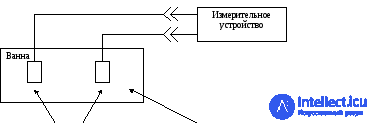
test reference electrode contact substance
electrodes
δ U = (U1 + U2) + Up
where U1 – the highest value of the electrode potential obtained during the measurement time, not counting the readiness time;
U2 – the lowest value of the electrode potential obtained during the measurement time, not counting the readiness time;
Up – the polarization voltage of the test electrodes at a polarization current value of 10-7 A.
The measuring device must have the following parameters:
measuring voltage range (0-100) mV;
permissible error limit +/- 5%;
constant component of the input current not more than 10-9 A.
The instability of the reference electrode potential must not exceed +/- 5mV.
The duration of continuous measurement from the moment the test electrode is brought into contact with the electrode contact substance is not less than 2 hours. If the measured electrode potential has a monotonic character, a short-term rather than continuous measurement is permissible.
Measurement of polarization voltage.
Diagram 2.
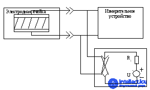




test switch source of polarizing
electrode polarity current
Ri – internal resistance of the source
U – DC voltage not less than 10 V
The measuring device must have the following parameters:
1.measuring voltage range (0-100) mV;
2.permissible error limit +/- 5%;
3.constant component of the input current not more than 10-9 A.
When the electrode potential difference stabilizes after the electrode is brought into contact with the electrode contact substance, it is measured. The switch is then set to the position in which the positive pole of the polarizing current source is connected to the positive pole of the electrode cell with the test electrodes. The new steady-state value of the electrode potential difference is measured. The polarization voltage equals:
Up = δU2 = δU1
The result is considered positive if the electrode potential difference is not more than 100 mV.
Measurement of voltage drift is performed according to diagram 1. A measuring device with the following parameters is used:
measured voltage range (0-1000) uV;
permissible error +/- 10%;
frequency response: lower limit 0.05 Hz (ECG electrode), 0.15 Hz (EEG electrode); upper limit frequency 1 Hz;
The constant component of the input current not more than 10-9 A;
The duration of continuous measurement is not less than 1 hour.
The drift value is calculated using the formula:
D = A/K,
where A – the (maximum) deflection amplitude [mm],
K – the sensitivity of the measuring device [mm/uV].
The result is positive if the drift is less than or equal to 250 uV (ECG), 25 uV (EEG).
1.6 Measurement of noise voltage is performed according to diagram 1. A 0.9% sodium chloride solution is used as the electrode contact substance.
The measuring device has the following parameters:
measured voltage range (0-1000) uV;
maximum permissible error +/- 10%;
frequency response: passband 1-75 Hz (ECG, EEG), 2*104 Hz (EMG with skin electrodes), 500*104 Hz (EMG with needle electrodes);
The duration of continuous measurement is not less than 1 hour.
The noise voltage values are calculated as the ratio of the [mm] deflection on the recording from maximum to minimum divided by the sensitivity [mm/uV]. Individual short-term voltage spikes are permitted no more often than once per second. Spikes exceeding 400 uV (for ECG) and 40 uV (for EEG) must not recur more often than once per minute.
Measurement of electromechanical noise voltage.
D iagram 3. cell test electrode
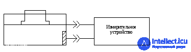


auxiliary electrode
The measuring device has the following parameters:
measured voltage range (0-1000) uV;
maximum permissible error +/- 10%;
frequency response: 0.05 – 7.5 Hz;
The duration of continuous measurement is not less than 1 hour.
+The voltage caused by two mechanical actions on the electrode is measured: tangential displacement of the electrode relative to the electrode matrix by 3mm in the forward and reverse direction; a change in the pressure of the electrode surface in contact with the electrode matrix from 5 to 10 kPa and back from 10 to 5 kPa. The time of tangential displacement or pressure change is not more than 0.1 seconds. The intervals between displacements or pressure changes are not less than 30 seconds. The number of displacements is not less than 4. The electromechanical noise voltage is the ratio of the deflection on the recording caused by the electromechanical noise voltage to the sensitivity [mm/uV].
The result is positive if the voltage does not exceed 100 uV.
Diagram 4.
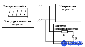


test electrodes U– sinusoidal voltage 0 – 10 V
Ri - internal resistance of the generator
The total impedance of the electrode cell is measured using the volt-ammeter method according to the formula:
Z = Uz / I
where Uz – the voltage drop across the electrode cell,
I – alternating sinusoidal current (A).
The permissible error limit of the measuring device is +/- 10 %.
The internal resistance of the measuring current generator must be greater than the total impedance of the electrode cell by at least a factor of 100.
The total impedance of each electrode is measured at the lower and upper boundary frequencies of the instrument. For an ECG electrode the lower limit is 0.05 Hz and the upper limit is 75 Hz. For EEG electrodes, respectively, 0.15 Hz and 75 Hz. The permissible error of the set frequency is +/- 5 %.
Z = Zp + Zp
at f = 150 Hz Zp >> Zp,
at f = 1 kHz Zp << Zp.
The voltage drop across the electrode cell is measured using an instrument whose error is +/- 10%, and whose total input resistance is 10 times greater than the resistance of the electrode cell at any of the frequencies at which the measurement is performed. The resistance value of each electrode is taken to be equal to half the total impedance of the electrode cell.
The electrode contact substance shall be tested as follows. The electrode contact substance is applied to white cotton fabric, which is protected from drying out, and held for 20 hours. The fabric is then rinsed with warm water and air-dried. A visual analysis of the fabric is then carried out, comparing it with fabric not exposed to the electrode contact substance. If the tested fabric shows no discoloration, the test results are positive.
Testing of the suction electrode with bulb for leak-tightness and measurement of the vacuum air pressure is carried out using the device shown in diagram 5.
Diagram 5.
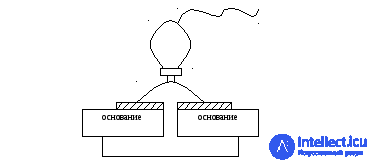




adhesive layer sealing vacuum gauge test
sheet electrode
δ = (P1 – P2) / P1 * 100%
Main parameters of the vacuum gauge:
measured vacuum pressure range 0 – 60 kPa;
permissible error 15 – 60 kPa +/- 5%;
the volume of the measuring chamber must not exceed 0.2 of the external volume of the suction electrode.
+The leak-tightness of the suction electrode is assessed through relative measurements of the vacuum pressure according to the formula, where P1 – the vacuum pressure measured 5 seconds after the electrode funnel is applied to the sealing sheet and compression of the bulb is stopped; P2 – the vacuum pressure measured 10 minutes after the electrode funnel is applied to the sealing sheet and compression of the bulb is stopped. If the direction and degree of compression of the bulb are not specified in the operating manual, the measurements are performed in several convenient directions evenly distributed over the surface until the walls of the bulb close. The result is taken as the arithmetic mean of not less than three measurements in each direction.
Measurement of bulb compression is performed according to diagram 6.
Diagram 6.
The part of the needle electrodes inserted into the tissue is immersed in a 10% citric acid solution at a temperature of 15 to 19 C. It is held in it for 5 hours and rinsed with distilled water. The needles are then boiled in distilled water for 24 hours. The electrodes are then removed from the water, dried and inspected: they must show no signs of corrosion.
Checking the sharpness of the needle tip of the needle electrode is carried out as follows. The needle electrode, fixed in a holder, must perform translational movements at a constant feed rate of 40 mm/min and pierce a polyethylene film 150 um thick, fixed in a frame. The maximum permissible piercing force after 24 punctures must correspond to the data given in the table:
|
d, mm |
Fmax, N |
|
0,3 |
0,6 |
|
0,4 |
0,7 |
|
0,5 |
0,8 |
|
0,6 |
0,9 |
|
0,7 |
1,0 |
|
0,8 |
1,1 |
|
0,9 |
1,2 |
|
1,0 |
1,3 |
|
1,1 |
1,4 |
The needle tip is tested for burrs by piercing cotton wool with the needle. After the puncture, there must be no cotton fibers on the needle tip.
The flexibility of a skin-neutral EMG electrode shall be checked by winding the electrode around a cylinder with a diameter of 30 mm or less. The electrode meets the requirements if continuous contact between the current-collecting surface of the electrode and the surface of the cylinder is maintained, as determined visually.
+Vibration resistance testing is carried out on a vibration test bench for 10 minutes. The electrodes are attached to the vibration bench table without any shock absorber.

Comments