
Lecture
Variable high-frequency, high-voltage currents were first obtained in 1891 by the Serb Nikola Tesla using a transformer he had invented. A year later, the French researcher J. A. d' Arsonval proposed using these currents for therapeutic purposes. This treatment was named darsonvalization. However, this term combines two independent therapeutic methods — local and general darsonvalization.
Local darsonvalization. The method consists of therapeutically affecting specific areas of the patient's body with a pulsed, variable electric current of high frequency and voltage at low current strength.
Currently, local darsonvalization uses an alternating current with a frequency of 110 kHz, modulated into a series of bell-shaped oscillations (pulses) following at a frequency of 50 Hz, at a voltage applied to the electrode of 25-30 kV. The pulse duration is 100 μs.
High-frequency current, passing through the rarefied air inside the electrode and its glass wall, forms a corona discharge in the layer of air between the body surface and the electrode wall. It can be «silent» with a small air gap and turn into a spark as the gap increases. When high-frequency current passes through the small capacitance formed by the glass and the electrode wall, the current is attenuated to a level that does not cause painful sensations.
Mechanism of therapeutic action. The factors acting on the body during local darsonvalization are the alternating high-frequency current passing through the tissues and the electrical discharges occurring between the body surface and the glass electrode as it moves across it. In cavity-contact application, the body is exposed only to the current factor.
At the frequencies used in darsonvalization, the current acts in one direction for such a short time that semipermeable membranes do not accumulate ions in quantities sufficient to bring the cell into a state of excitation. At the same time, frequent reversals of current direction cause tissue ions to undergo oscillatory motion, generating heat. This heat is small, since the periods of oscillation (pulse duration), lasting 100 μs, alternate with pauses 100 times longer. The highest current density during exposure occurs in the tissue areas in contact with the electrode. It is here, specifically in the superficial tissues, that the greatest heat generation also occurs. In deeper tissues, due to the current spreading throughout the whole body, its density decreases significantly.
Corona, quiet and especially spark discharges, in fact, also have a thermal effect. However, due to the concentration of heat at several points, these discharges have a predominantly irritant effect on the superficial tissues and the receptors located in them. Under the influence of this irritation, which constantly moves across the exposure zone, as well as the heat generated within the tissues, the arterioles and capillaries of the exposed area dilate, blood circulation is enhanced, and visible hyperemia of the skin appears.
Dilation of blood vessels and increased blood flow through them occur not only when they are in a normal state, but also as a result of relaxation, under the influence of the currents, of spastically constricted vessels and a reduction of their elevated tone. At the same time, the cessation of vascular spasm and dilation of their lumen occur not only in the areas of skin exposed to the treatment, but also in internal organs segmentally connected with these areas. Thus, O. D. Grigorieva and N. D. Gorelik (1947) state that darsonvalization of the heart area promotes dilation of the coronary vessels, improved myocardial nutrition, and normalization of heart rhythm in tachycardia in patients with coronary heart disease of moderate severity.
Activation of blood circulation, including in the walls of the vessels themselves, improves their functional state, which, combined with the cessation of vascular spasm and ischemia, increases the activity of metabolic-trophic processes, especially in the skin with its appendages and subcutaneous tissues, which is widely used for disorders of skin trophism. Local darsonvalization has found wide application in cosmetic practice, in particular for improving the functional state of the skin, increasing its elasticity and turgor, and for preventing the development of wrinkles and hair loss.
As a result of extensive afferent impulses from the receptors of exposure to the central nervous system and its autonomic centers, paresthesias, pain, and itching are reduced or stopped.
The reactions listed above also underlie the anti-inflammatory effect of local darsonvalization in minor chronic inflammatory processes located in the skin, the mucous membrane, and in the tissues adjacent to them.
To perform local darsonvalization, a vacuum glass electrode is applied firmly to the treatment site or inserted into the cavity (for cavity procedures). The high voltage is then switched on and the current strength is smoothly increased until the patient feels very slight warmth during cavity procedures, or tingling during surface procedures. Then, for surface exposures, the vacuum electrode is moved with a smooth motion over the talc-powdered body surface to be treated. If a weak effect is required, along with using a low current strength, the vacuum electrode is moved without lifting it from the patient's body surface. If an irritant effect is indicated, along with using a high current strength, the vacuum electrode can be moved while lifting it, as far as possible, above the body surface (to produce a stronger spark discharge).
At the end of the procedure, the current is switched off first, and then the electrode is removed from the body surface. This order must be observed especially carefully during cavity procedures, so as not to cause the patient an unpleasant sensation. After the electrode is removed from the cavity, it should be thoroughly washed with warm water and soap, and then immersed in some disinfectant solution, where frequently used electrodes may remain until the next procedure. Vacuum electrodes must not be boiled. After a surface exposure with a vacuum electrode, the body surface is wiped with alcohol or a swab moistened with warm water.
Darsonvalization of the scalp is performed with a comb-shaped vacuum electrode after removing hairpins and other metal objects from the hair.
The duration of exposure to one area of the body can be from 3 to 10 minutes, with a course of treatment of 8—12 procedures, most often performed every other day.
In local darsonvalization, its effect does not confine itself to the site of electrode application alone, but extends to the whole body, so during the procedure no one should touch the patient. The patient himself should also not touch anyone, and should not touch metal objects, since sparks will jump at the point of contact.
Local darsonvalization is indicated for varicose veins of the legs and hemorrhoidal veins, anal fissures, the aftereffects of frostbite, long-term non-healing wounds, trophic ulcers, neurodermatitis accompanied by itching, auditory nerve neuritis, angina pectoris, and neuralgia.
General darsonvalization consists of therapeutically exposing the patient's entire body to a pulsed alternating electromagnetic field of high frequency and voltage. To perform it, the patient is placed inside a solenoid, through whose coils current is passed. Modern general darsonvalization devices use a current with a frequency of 140 kHz, with an oscillation series (pulse) duration of 20—30 μs at a repetition frequency of 100 Hz. As the current passes through the coils of the solenoid, it creates a high-frequency magnetic field inside it with a maximum induction of 1 — 2 mT. Owing to the capacitive coupling between the solenoid coils and the patient's body, a high-frequency electric field also acts on the patient. Thus, the body of a patient inside the solenoid is exposed to a high-frequency pulsed electromagnetic field. The patient does not experience any sensation of warmth or anything else.
When exposed to electromagnetic oscillations, eddy currents are induced in the patient's body, and it is these that act as the factor directly affecting the organism. The power of these currents is small. As a result of their action, a sedative effect and a reduction in blood pressure that had risen due to functional vasomotor disorders are observed.
Procedures lasting 10 — 20 min are usually performed every other day, with a course of treatment of 10-12. General darsonvalization is not performed in children.
Indications for general darsonvalization: hypertension stage I-II, functional disorders of the central nervous system, climacteric neuroses, insomnia.
Contraindications for local darsonvalization: febrile conditions, intolerance to the treatment, malignant neoplasms, bleeding, active pulmonary tuberculosis. Contraindications for general darsonvalization, in addition to those listed, include cardiovascular insufficiency, cerebral circulatory disorders, and hypertension stage III.
Very close to local darsonvalization in essence and methods of therapeutic application are ultratonal-frequency currents, proposed in the early 1960s by D. A. Sinitsky.
The essence of the method is that specific areas of the patient's body are treated therapeutically with a sinusoidal high-frequency current, delivered through a glass electrode filled with neon.
The method employs a continuous sinusoidal current with a frequency of 22 kHz and a voltage of 4.5—5 kV at a maximum power of up to 10 W. As with local darsonvalization, when ultratonal-frequency currents (UTF) are applied, a spark discharge occurs between the glass electrode and the patient's body. Under the influence of the discharge, a small amount of ozone is formed.
Mechanisms of therapeutic action. The acting factors in the application of ultratonal-frequency currents are the high-frequency alternating sinusoidal current and the spark discharge, i.e., the same factors as in local darsonvalization. However, they differ in their parameters and have a different effect on the body. Due to their continuity, and consequently the greater amount of current acting per unit of time, ultratonal-frequency currents cause greater heat generation in the tissues — during exposure, patients feel moderate warmth. The considerably lower voltage at the electrode practically eliminates the irritant effect of the current when performing the procedures. Under the influence of heat and the mild stimulating effect of the spark discharge in the tissues subjected to direct action, and to a greater degree in those adjacent to the electrode, UTF enhances local blood circulation, increases the activity of metabolic processes, reduces congestion and pain, improves the functional state of the neurovascular system, and exerts an antispasmodic effect. The presence of these components provides an anti-inflammatory effect.
UTF exposure is performed with glass electrodes of the same shape and in the same way as with local darsonvalization. The intensity of the exposure is adjusted until the patient feels moderate warmth, while attention is paid to the glow of the gas in the electrode. As the power increases, the brightness of the glow also increases.
Treatments are performed for 5—20 min, daily or every other day, with a course of treatment of up to 20 procedures.
UTF is indicated mainly for local inflammatory processes in cases where it is possible to ensure contact of the electrode with the tissues involved in the pathological process: in urological diseases of children, diseases of the skin and mucous membranes, and in dental practice. These currents are used for chronic salpingo-oophoritis with infantilism, and for seborrheic alopecia.
Contraindications for the use of ultratonal-frequency currents are the same as for local darsonvalization.
Ultra-high-frequency therapy is the therapeutic application of an effect on specific areas of the body of the patient by a variable continuous or pulsed electric field of ultra-high frequency (UHF field).
Interest in ultra-high-frequency electromagnetic oscillations began to emerge in connection with the development of ultra-short-wave broadcasting, when their effect on operating personnel was noticed. For therapeutic purposes, the UHF field was first applied in 1929 by E. Schliephake in Germany. Since then, this distinctive type of treatment has developed rapidly and become widespread in many countries. It served as the basis for the development of treatment with even higher frequencies.
Ultra-high frequencies include electromagnetic oscillations with frequencies of 30 —300 MHz, corresponding to wavelengths from 10 to 1 m (ultra-short waves).
In most countries, UHF therapy uses devices operating at a frequency of 27.12 MHz (wavelength 11 m). Devices previously manufactured in our country operate at a frequency of 40.68 MHz (wavelength 7.38 m). Newly developed UHF therapy devices have a frequency of 27.12 MHz. This frequency is preferred because, both in our country and abroad, a greater tolerance is allowed for deviations of the oscillation frequency from the approved value during the operation of the devices, which considerably simplifies and reduces the cost of their production and operation in accordance with current standards.
Another general characteristic of UHF exposure is the power of electromagnetic oscillations delivered by the device. Owing to improvements in equipment and better matching with the load, power of up to 300 W is currently used for local or regional exposures. If we speak of the power absorbed by the patient's body, these values should be reduced by approximately half.
In terms of its physical properties, energy-absorption mechanism, and effect on the body, the UHF therapy method has no equal among other physical factors. This is explained primarily by the fact that the main and only factor acting on the body in this method is the alternating electric field. According to modern concepts, an electric field is a special form of matter through which interaction between electrically charged particles takes place. Consequently, if some part of the body is placed in an electric field, for example between two oppositely charged plates, it will affect the electrically charged particles of the body (ions). This influence consists in the fact that the ions move toward the oppositely charged plates, forming a conduction current. The dipole particles of the body change position under the influence of the field forces, orienting their charges toward the oppositely charged plates. Dielectrics that do not have a structural dipole temporarily acquire one — they become polarized.
When the direction of the electric field changes, the processes listed above occur in the reverse direction. Thus, with each reversal of the field direction, the direction of the processes changes.
Under conditions of UHF exposure, when the direction of the electric field changes 27 or 41 million times per second, the polarization and relaxation-type ionic oscillation processes mentioned above are accompanied by significant generation of intratissue heat. Its amount increases with increasing frequency of the alternating field, and at the same frequency is determined by the properties of the tissues, in particular by their capacity for polarization, which depends on the nature of the substance, characterized by its dielectric permittivity and electrical conductivity.
Owing to the very high frequency, the capacitive resistance of the tissues decreases significantly, and they become readily permeable to the energy of high-frequency oscillations. Air acquires roughly the same capacitive conductivity, so the UHF electric field freely passes through the air gap between the capacitor plate and the body, through the skin with its subcutaneous fat layer, fatty connective-tissue layers, and penetrates inside the joints, through bone into the bone marrow and into other tissues inaccessible to other types of energy. This is an important advantage — a specific feature of the UHF therapy method. With the capacitor technique, as with no other method, a through effect on all layers of tissue is achieved. However, the maximum amount of energy is absorbed in the subcutaneous fat layer.
The body reacts to the UHF field as a single whole, but the nervous system is the most sensitive to its effect, having a lower excitation threshold and, in the course of evolution, having adapted to perform a connecting role between the external environment and the organism.
The nature and severity of the reactions of the nervous system and the whole body to the UHF field depend on the initial state of the body and its individual characteristics. In a pathological state, changes in body functions under the influence of UHF field exposure are more pronounced than in a normal state.
In response to a low-thermal dose of the UHF field, the nervous system, like other systems of the body, responds with excitation. This is evidenced by changes in nerve excitability and conductivity under the influence of UHF field exposure, and by changes in the behavior of experimental animals, which is a direct and, at the same time, a clear reflection of nervous system activity.
With exposure to large doses, or with prolonged exposure to small doses, a brief phase of excitation is observed, followed by inhibition.
UHF exposure in small doses accelerates the regeneration of damaged nerves, while large doses inhibit it.
The human vascular system is sensitive to the action of UHF. Studies on isolated organs reveal a clear relationship between vascular response and the intensity of exposure. At low intensity of exposure. At low intensity, dilation of arterioles and capillaries occurs, along with acceleration of blood flow. At high doses, constriction of capillaries and arteries occurs, with slowing of capillary and venous blood flow.
Technique of performing the treatments. Capacitor plates are most often made in the form of round metal discs insulated with plastic or glass shells. Such capacitor plates are fixed to the patient's body using electrode holders attached to the housing of the device. In addition to flat capacitor plates of various diameters, special capacitor electrodes are also made; for example, for vaginal treatments, they are made in the form of a metal rod in glass or plastic insulation. For treatment of the armpit area in hidradenitis, the capacitor electrode has the shape of a prism with a rounded edge. For treating furuncles, capacitor electrodes with a concave surface are used. Flexible capacitor plates of various sizes are also used. They consist of metal mesh or foil pressed into a rubber shell. Such plates are fixed by tying them with an elastic bandage or straps. To create the necessary gap between the capacitor plate and the patient's body, felt pads are placed in between.
UHF field exposure is administered by positioning well-insulated capacitor plates at a certain distance from the surface of the body area being treated. The distance between the body surface and the capacitor plate - the gap), as well as between the two plates, is of decisive importance for the distribution of the electric field between the plates and for the topography of energy absorption in the body area being treated. A uniform field is formed between two capacitor plates if the distance between them is less than their diameter. However, even in this case the field density decreases at the edges of the plates. (edge effect).
When a body area is placed between the electrodes, the uniformity of the electric field is disrupted and its greatest density forms directly at the plates. Therefore, if the capacitor plates are placed against the body without a gap or with a very small gap, the greatest energy absorption and heating will occur in the superficial tissues. At depth it will be insignificant; but if the capacitor plates are placed at a distance of several centimeters from the body surface, then in this case energy absorption occurs more evenly in the superficial and more deeply located tissues. Consequently, for exposure to the UHF field on deeply located tissues it is necessary to set a gap of several centimeters. In this case, however, it must be kept in mind that with an increase in the gap the dissipation of energy into the surrounding space increases and the total amount of field energy absorbed by the patient’s body decreases. To carry out exposures with large gaps, apparatuses of at least medium power must be used.
The versatility of the therapeutic action of the UHF field determines broad indications for its use. First of all, the use of the UHF field is indicated for inflammatory processes of any localization, including the brain and spinal cord, the endocrine glands, and other regulatory systems. The intensity of exposure should be determined by the stage of the inflammatory process. In its initial stages, the stage of infiltration, i.e. the «acute» stages, exposures causing a sensation of mild warmth are used. Such exposures often halt the inflammatory process and prevent suppuration. This is especially clearly seen in furunculosis and traumatic injuries with disruption of tissue integrity.
In a developed purulent process, the UHF field can be used only if there is drainage of the pus. When the acuteness of the inflammatory process is not sharply pronounced, exposures with a moderately pronounced sensation of warmth are used. In chronic, sluggish inflammatory processes, exposures with a well pronounced sensation of warmth are used.
The UHF field is widely used for various circulatory disorders.
Pathology of the peripheral nervous system is also an indication for the use of the UHF field. These are — injuries of peripheral nerves and plexuses, painful phenomena — neuralgia, causalgia, phantom pain, pain in neuritis, polyneuritis.
The UHF field is widely used for diseases of the respiratory organs: rhinitis, sinusitis, acute and chronic pneumonia, pulmonary-cardiac insufficiency not exceeding stage II, bronchial asthma.
The UHF field is used for trophic ulcers, long non-healing wounds, frostbite, furunculosis.
Contraindications: febrile states, tendency to bleeding and hemorrhage, purulent processes without drainage of pus, malignant neoplasms, systemic blood diseases, circulatory insufficiency of stage III, pregnancy, when the exposure is localized on the lower abdomen and pelvic area.
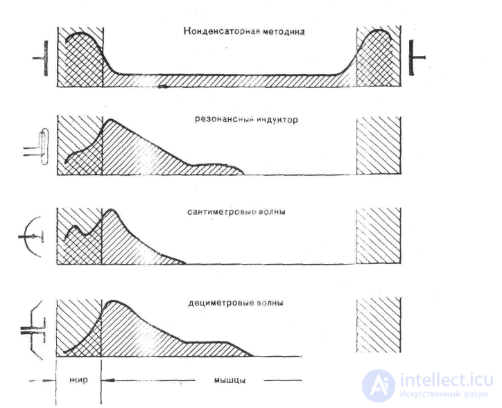
Fig. 1. Graphic representation of the ratio of the amount of electromagnetic field energy of the UHF and SHF (microwave) ranges absorbed by tissues
Centimeter-wave, microwave therapy – the therapeutic use of exposure of certain areas of the patient’s body to electromagnetic oscillations of ultra-high frequency. A frequency of 2375 MHz has been allocated for centimeter-wave therapy. This corresponds to a wavelength of 12 cm. This is due to the very high frequency, approaching the frequencies of light waves of the IR range. Waves of this range cannot be transmitted over wires. Coaxial cables are used for this purpose. Unlike UHF therapy, plates or circuits are not used to deliver centimeter waves to the patient’s body, but rather an emitter with a reflector, resembling a lamp with a reflector. When microwave radiation is directed at one area of the body, the energy of the oscillations is partly absorbed and partly reflected by the surface of the skin owing to the large difference between the dielectric permittivity of air and the permittivity of the skin with the subcutaneous fat layer; the reflection is large and can reach up to 70% . In addition, the amount of absorption and reflection can vary widely from case to case. The energy of microwave oscillations, penetrating through the skin, is absorbed to the greatest extent by tissues with the highest water content, whose molecules possess polarization properties, whose relaxation frequencies are close to the frequency of the acting oscillations. Accordingly, the depth of penetration of SMV (centimeter waves) into tissues with a high water content (muscle, skin, biological fluids) is 1.7 cm. In tissues that weakly absorb microwaves (fat, bone, etc.), the depth of penetration is 11.2 cm. On average, owing to the complex composition of tissues, the depth of penetration of SMV from the body surface is 3- 5 cm.
The result of SMV energy absorption, associated with the oscillation of polar water molecules, is the generation of a significant amount of intratissue heat. The largest share of heat from the absorbed energy falls on the muscle layer, although the skin and the subcutaneous fat layer are also heated well.
Owing to the significant difference in the dielectric permittivities of fatty and muscle tissue, reflection of the oscillations occurs at their interface, just as at the boundary between air and skin. With different ratios of tissue layer thickness, especially with a well-developed subcutaneous fat layer, if its thickness is a multiple of the wavelength, standing waves may arise, leading to overheating of points or zones in the tissues and even to burns, which is one of the drawbacks of the centimeter range and requires caution when carrying out procedures.
SMV is a factor with a highly diverse and intensive effect on many organs and systems of the body. This indicates that it can be used for therapeutic purposes in many pathological conditions, mainly in subacute and chronic inflammatory diseases, as well as in dystrophic processes.
Apparatus.
Portable apparatuses for SMV exposure include the «Luch-2» and its upgraded versions «Luch-2M» and «Luch-3». These apparatuses are designed for exposures on small, limited areas of the body using the contact technique. Their radiation frequency is 2375 MHz (wavelength 12.6 cm). The output power is adjustable in seven steps from 2.5 to 20 W. The apparatus is made to protection class I against electric shock. It is supplied with three emitters with hand-held holders. The emitters are cylindrical waveguides excited by the radiation of a metal pin. The emitters have diameters of 1.5, 2.5 and 3.5 cm. Caps made of high-frequency dielectric are placed on the radiating ceramic surface, which are disinfected by the wet method. The set includes vaginal and rectal emitters. They are made in the form of ceramic rods. The vaginal emitter has a metal coating at its end and creates a microwave field concentrated at the end, while the rectal one creates it along its entire length. Caps that allow processing by boiling are placed on the ceramic surfaces of the emitters. The set includes one large cylindrical emitter with a diameter of 11.5 cm. It has no ceramic filling but is used in contact mode, like the others.
The «Luch-58» apparatus is mobile, designed for remote exposure to larger areas of the body than the «Luch-2». Its maximum power is 150 W. It is adjustable from 16 W in steps of 35 W. The apparatus is supplied with three cylindrical waveguide-type emitters with diameters of 9, 11 and 14 cm and one rectangular emitter measuring 30x9x9 cm. A coaxial cable from the apparatus is inserted into and secured in openings on their lateral surface. The central conductor of the cable, in the form of a metal pin, is the exciter of the oscillations. The opening of the cylindrical and rectangular emitters facing the patient is covered with a plate of high-frequency dielectric.
To protect personnel from the effect of scattered radiation, which occurs during remote exposure, the «Luch-58» and «Luch-11» apparatuses must be operated in separate closed rooms or in a shared physiotherapy room, but with mandatory shielding of the cubicle with special protective fabric. For this purpose, instead of the usual material dividing the cubicles, the mentioned fabric is secured with rings to the metal tubes of the cubicle frame in such a way that there are no gaps. At the entrance, one strip should overlap the other by 15—20 cm. There should also be no gaps between the floor and the fabric. If the cubicle is located in a corner of the room, the load-bearing walls do not need to be covered with fabric.
To protect the patient’s eyes during exposure to the head, protective goggles ORZ-5 are used.
Technique of administering the exposure.
Beforehand, all metal objects are removed from the exposure zone. If metal objects are present within the tissues at a depth of less than 2 cm, exposure should not be carried out on that area. Then the apparatus and emitter are selected according to the size and configuration of the area to be exposed. For small areas, ceramic emitters are used, which are applied directly to the body without exerting pressure on it (so as not to cause impairment of blood circulation). The large non-ceramic emitter from the «Luch-2» and «Luch-3» apparatuses is attached with a rubber bandage so that the working surface lies against the body. In remote techniques, the emitter is fixed in a holder so that its working surface is positioned opposite the area to be exposed, at a distance of 5—6 cm from it. During the procedure, the patient’s sensations must be monitored, preventing the appearance of a burning sensation. If there are complaints of burning, the power must be reduced.
The main criterion for selecting the intensity of exposure (dosage), as with other methods of high-frequency electrotherapy, is the patient’s sensations. In this connection, a distinction is made between low-thermal, thermal, and strongly thermal intensities of exposure. Because with contact techniques there is no reflection of energy from the skin surface, the power absorbed by the patient can be judged from the meter readings on the apparatus. With the remote technique, because of the great variability in the amount of reflected energy, the absorbed power cannot be judged from the meter readings.
Low-thermal and thermal intensities are used more often. The exposure time is prescribed from 4 to 15 min per field. The total duration of exposures to several areas should not exceed 30 min. Exposures are carried out daily or every other day. The total number of them per course of treatment is 8—15.
Indications: Subacute and chronic inflammations, dystrophic diseases of the musculoskeletal system, with the exception of the hip joint. Ligament sprains, neurological manifestations of spinal osteochondrosis, chronic inflammatory diseases of the respiratory organs — chronic bronchitis, protracted acute and chronic pneumonia, inflammatory and dystrophic diseases of various parts of the eyes, chronic inflammatory diseases of the pelvic organs.
Contraindications: tissue edema. Presence of metallic foreign bodies in superficial tissues. Exposure through damp clothing. Exposure in the zone of growing bones in children, pregnancy, active pulmonary tuberculosis, systemic blood diseases, ischemic heart disease above stage two.
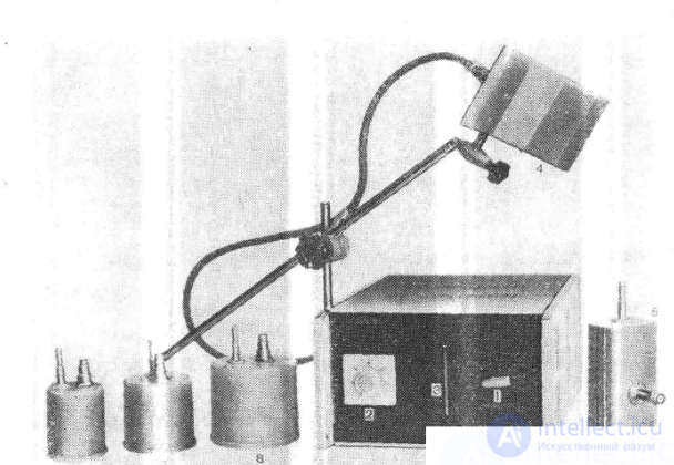
Fig. General view of the microwave therapy apparatus SMV-150-1 -Luch-11». 1 — power switch and mains voltage switch-on; 2 — timer with high-frequency switch-on; 3 — gas-discharge tube, the glow of which indicates the power level; 4 — lightweight emitter; 5 — rectangular emitter; 6, 7, 8 — cylindrical emitters.
developed by VNIIMP, modernized and manufactured by the Moscow EMA plant. The small mass and dimensions of the apparatus allow it to be used for procedures at the patient’s bedside at home or in clinical settings. For use in pediatric medical practice, the apparatus has a reduced-power mode.
Main technical data of the apparatus: generator frequency 40.68 MHz+2%; output power is adjustable in two steps — first step 15 W, second step 30 W; powered from an AC mains supply with a frequency of 50 Hz, voltage 220 V +5%, —15%; maximum power consumption from the mains — 160 VA; the apparatus is made to protection class 01 against electric shock; overall dimensions of the apparatus housing 425X275X230 mm; mass (with accessory set) not more than 12.5 kg.
The basic electrical circuit diagram of the UHF-30 apparatus is shown in Fig. III—42. The self-excited generator is built according to a push-pull circuit using a double-beam tetrode GU-19 (L1). The self-oscillator circuit is two-circuit. The anode circuit is formed by inductor 7, the output capacitances of the GU-19 tubes, and the semi-variable capacitor6, with the help of which the factory adjustment of the self-oscillator frequency is carried out.
The grid circuit is formed by inductor 8 and the input capacitances of tubeL1. Feedback is provided through the tube's pass-through capacitances, in parallel with which are connected capacitors5, 7. Resistor 1 of the automatic bias is connectedto the point of zero high-frequency potential of inductor 5. The filament is blocked at high frequency by capacitor9, and the screen grid — by capacitor8.
By means of inductive coupling through a loop formed by inductor 3 and turn6, the generator’s anode circuit is connected to the output circuit (the patient circuit). Turn6 has a grounded electrostatic shield, which significantly reduces the capacitive coupling between the anode and output circuits. Combined with the balanced push-pull generator circuit, this makes it possible to sharply reduce the apparatus’s radiation of even harmonics.
Inductors 4 and 5, with capacitor4, form a low-pass filter designed to filter out harmonics.
The output circuit includes inductors 1 and 2 and a variable capacitor 1. The capacitor is used to tune the circuit into resonance with the generator frequency during the procedure.
Power is supplied to the generator tube anodes from a rectifier built according to a full-wave circuit using rectifier stacks D2, D3, with three filter capacitors10—12 connected in parallel. The anode supply voltage from the rectifier output is fed to the midpoint of anode-circuit inductor 7 through chokeDr.
The screen grid of the GU-19 tube is powered from the same rectifier through dropping resistor 2.
Switching the apparatus to the reduced-power mode is done using switch B2, which switches dropping resistor6 into the rectifier circuit.
The rectifier and the filament circuit of the generator tube are powered from the mains transformer Tr. The primary winding of the transformer has taps connected to switchV3 «Compensator». This switch is used to set the rated supply voltage of the apparatus. The supply voltage can be monitored using meterIP. For this purpose, it is connected, by means of pushbutton switchV1 «Voltage Control», to the filament winding of the transformer through semiconductor diodeD1 and resistor 7. The resistor is selected so that, at the rated filament voltage, the meter’s needle is in the middle of the red sector on its scale.
When switch button V1 is not pressed, meterIP is connected in parallel with resistor3. In this case, its reading is proportional to the sum of the constant components of the anode current and the screen-grid current of the generator tube. Also included in the cathode-current circuit is incandescent lampL2, shunted by resistor4. The tuning of the output circuit into resonance with the generator frequency can be judged from the maximum deflection of the meter’s needle and the greatest brightness of the lamp’s glow.
Design of the apparatus. The apparatus (Fig. III—43) is mounted in a rectangular metal housing with a removable back wall. Brackets 1 are fixed on the right side wall, in which hinged electrode holders 2 are mounted. The design of the hinges ensures reliable automatic fixation of the holders in all possible positions. Output sockets for connecting the electrode leads are located above the brackets.
On the two-tone front panel are located: on the left — meter 3, above it the indicator window 4 of the signal lamp, below it knob 5 «Power»; on the right — knob 6 «Tuning» and knob 7 «Compensator»; in the middle — button 8 «Voltage Control».
For ease of carrying, the apparatus is equipped with a folding handle 9 (shown in the raised position).
The parts and circuit elements of the apparatus are mounted on a chassis that slides into the housing and is secured with four screws through holes in its base. A view of the chassis is shown in Fig. III—44. The generator section is separated from the output circuit by a vertical partition 1, which has spring contacts 2 at the top, providing good electrical connection with the housing cover. The horizontal chassis panel has similar contacts for connection with the right side wall of the housing.
The generator tube is secured with a clamping ring and connected to the anode circuit (inductor 4, capacitor 5) by flexible wires in porcelain insulators.
The meter located in the same compartment is separated by shield 6. Signal lamp 7 is mounted above the meter.
Coupling turn 8 is made of flexible coaxial cable, whose braid has a break to provide magnetic coupling of the turn with the anode circuit.
The output circuit — inductors 9 and variable capacitor 10 — is made as a single unit.
Brought out to the rear wall of the chassis are: fuse holders 11, appliance inlet 13 for connecting the mains cord, which plugs directly into the mains filter shield, and protective grounding terminal 14.
A view of the chassis from below is shown in Fig. III—45. The power transformer 1 is mounted in the center; next to it are rectifier stacks 2 and filter capacitors 3 connected in parallel.
Located under the panel of the generator tube are grid-circuit inductor 4, output-power adjustment resistor 5, and dropping resistor 6 in the screen-grid supply circuit.
Mounted on the rear wall of the chassis is shield 7 of the mains filter; on the front — switch 8 of the mains-voltage-deviation compensator, button 9, and power switch 10.
In addition to 3 pairs of round electrodes with capacitor-plate diameters of 36, 80 and '113 mm, the apparatus set includes a resonant inductor EVT-1 (sometimes called an eddy-current applicator) and a tuning indicator — a neon lamp in a holder made of insulating material.
The resonant inductor is used to expose the patient’s body tissues to the UHF magnetic field. Shown disassembled in Fig. III—46, the inductor is a circuit tuned to the generator frequency, consisting of inductor 1 and capacitor 2. The inductor has a special shape that ensures minimal exposure to the electric field. The end turns are set back from the end plane facing the patient, which reduces the capacitive coupling of the coil ends, which have the highest electric potential, with the patient’s body tissues.
The capacitor and inductor are mounted on base 3, onto which protective cap 4 is screwed. The base and cap are made of high-frequency dielectric. The inductor is connected to supply wires 5 by means of connectors 6. Pins 7, with which the wires terminate, are inserted into the output sockets of the apparatus.
The inductor is secured in the electrode holder by screw 8.
When carrying out procedures using the resonant inductor, it is positioned so that the end of the cap either directly touches the body surface or is at a distance of no more than 0.5 cm from it. The second, free electrode holder is moved aside in this case.
Operating the apparatus during procedures. After setting the «Compensator» knob and the power switch knob «Power» to the off position, the apparatus housing should be grounded and the mains cord plug inserted into the wall socket.
Before the procedure, the patient should assume a comfortable position that he or she can maintain without strain until the end of the procedure. Watches, rings, earrings, and other metal objects located in the exposure area must be removed. The capacitor electrodes or the inductor are positioned as needed relative to the patient by means of the electrode holder. When carrying out procedures on young children, it is recommended to place felt pads under the electrodes and secure the electrodes with a rubber bandage. This will prevent detuning of the circuit due to the child’s inevitable movements.
After installing the electrodes, the compensator knob is switched to position «1». This causes the signal lamp to light up. After pressing the meter’s switching button, the knob is turned until the meter’s needle settles within the red sector of its scale. After waiting 1/2—2 min, the «Power» knob is switched to position «15 W» or «30 W» and the output circuit is tuned into resonance. The tuning is checked using the neon-lamp indicator. The lamp is brought close to the electrodes, and, by turning the «Tuning» knob, its maximum glow is achieved. The tuning can also be checked by the maximum deflection of the meter’s needle (with the switch button not pressed).
At the end of the procedure, the power switch knob is switched to the off position. If no more procedures will be carried out, the mains-voltage compensator knob is also switched to the off position, and the mains cord plug is removed from the wall socket.
The portable UHF-66 apparatus for UHF therapy was developed by the Lviv EMA Design and Technology Bureau and is manufactured by the Lviv REMA plant. The apparatus differs significantly from its predecessor — the UHF-4 apparatus (see the 4th edition of the book). It employs an improved radio-interference protection circuit, an eased thermal regime for the generator tubes, extended output-power adjustment limits, an enlarged set of electrodes, etc. Main technical data of the apparatus: generator frequency — 40.68 MHz+2%; maximum output power 70 W; powered from an AC mains supply with a frequency of 50 Hz and a voltage of 220 V +10%; power consumption from the mains not more than 500 VA; the apparatus is made to protection class 01 against electric shock; overall dimensions 547X320X315 mm; mass with electrode holders not more than 30 kg. The apparatus consists of the following main units: generator, output circuit, power supply unit.
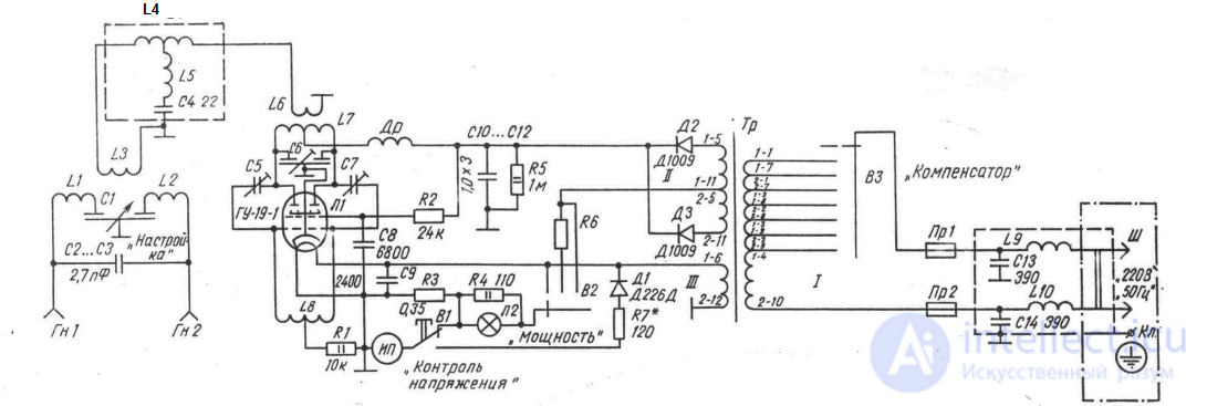
Fig. 1. Basic electrical circuit diagram of the UHF-30 apparatus.
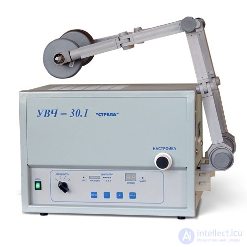
Fig. III— 43. General view of the UHF-30 apparatus.
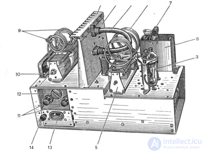
Fig. III— 44. Top view of the chassis of the UHF-30 apparatus.
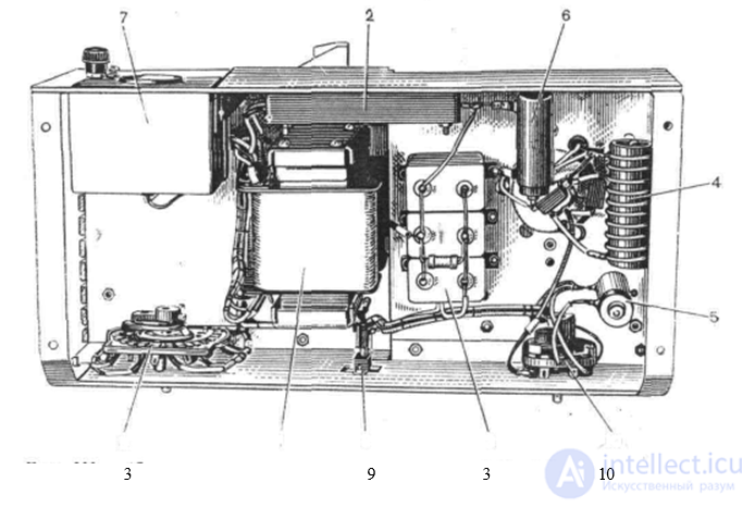
Fig. III—45. Bottom view of the chassis of the UHF-30 apparatus-
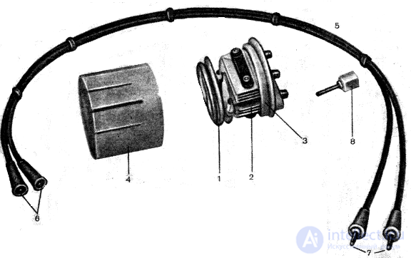
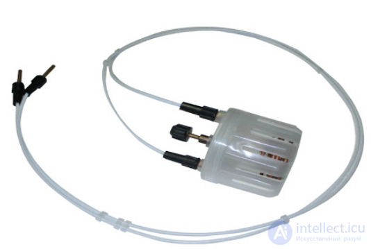
Fig. Ill— 46. Resonant inductor EVT-1.

Comments