
Lecture

3
Basic:
1 Electrodes
2 Connecting wires
3 Input device
4 Amplifier
5 Recorders
6 Power supply unit
Additional:
7 Calibration signal source
8 Ohmmeter
9 Analyzers, stimulator
Electrodes for picking up biopotentials from the body surface are conductive (metal) round and rectangular plates of small area, from 0,3-30 cm2. The electrodes are secured to the body with rubber straps, rubber suction cups, or a special head cap. Strip electrodes are used, in the form of gastric tubes and cardiac catheters, as well as needle electrodes inserted into the tissue under study (muscles, brain). To improve recording quality and reduce the effect of external interference, a low electrode-skin resistance must be ensured. Electrochemical processes occur on the surface of the electrode in contact with the electrolyte, giving rise to electrode potentials. The difference between these potentials can reach 100 mV, considerably exceeding the potentials being recorded. Large values and instability of the electrode potential difference can lead to significant interference and errors when recording biopotentials. Silver chloride electrodes have a small and sufficiently stable electrode potential difference.
The input device provides for the creation of a specific lead system connected to the amplifier input. This system may include connections to the electrodes and resistors for obtaining an artificial reference point relative to which biopotentials are measured. The number of electrodes placed on the patient simultaneously usually exceeds the number of channels of the instrument. For this reason, the input device has switches that allow any pair of electrodes to be connected to any channel as selected. Program-controlled switching is used, in which a single switch connects a specific pair of electrodes to several channels according to a predetermined program. A calibration signal from a well-stabilized source is fed into the input device, making it possible to evaluate the magnitude of the biopotentials being measured. The calibration signal has one or several fixed values.
In a number of cases it is important to know the inter-electrode resistance. For this purpose an ohmmeter is installed in the instrument, to which any pair of electrodes can be connected by a separate switch on the input device.
The input device may contain interference-suppression elements. These are filters to protect against high-frequency fields and a common-mode interference suppressor. When the amplifiers contain filters tuned to the mains interference frequency, a voltage with a frequency of 50 Hz can be fed into the input device for periodic adjustment of the filters. Biopotential amplifiers must amplify the biopotentials being picked up without significant distortion. Depending on the purpose of the instrument, one or several amplification channels are used, which are identical amplifiers. Depending on the purpose of the instrument, the gain is 10000(ECG)-200000(EEG). Such gain is achieved by using several amplification stages. To exclude interfering biopotentials from other organs or to isolate a particular part of the spectrum of the potentials being recorded, the amplifier may have adjustment of the upper and lower passband. If the biopotentials have a pronounced fundamental oscillation frequency, a selective amplifier is used, which amplifies the voltage in a narrow frequency band. The inter-electrode resistance for skin-surface electrodes is tens of thousands of Ohm. And when using needle electrodes, several MOhm.
One of the most important characteristics of an instrument used for recording biopotentials is its noise immunity. Interference in biopotential recording can be divided into internal and external.
Internal interference includes the amplifier's thermal noise, caused by the chaotic motion of electrons in resistors and by nonstationary processes in electron tubes and transistors, and mains-frequency hum, the sources of which can be ripple in the voltages supplying the amplifier or pickup from the alternating magnetic field produced by the power transformer.
Measures for combating internal interference include selecting low-noise components, thorough filtering of supply voltages, shielding, and improving the design of the instrument.
External interference can be subdivided into interference from biopotentials of tissues and organs not related to the process under study, interference caused by electrochemical processes at the electrodes, and interference produced by external electric, magnetic, and electromagnetic fields.
From the amplifier output, the amplified biopotentials are fed to the recorder. With the recorder, the biopotentials are represented as a curve recorded by one method or another, which can then be subjected to analysis. Ink and thermal recording are the most widely used. The main part of the recorder is the vibrator – by means of which an alternating voltage is converted into oscillatory motion of a rotor, on whose axis a writing device is mounted.
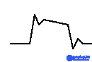
The vibrator consists of a strong permanent magnet, to whose poles pole tips 3 are attached. Between the pole tips is coil 1, through which the current from the transistors or tubes of the amplifier's output stage flows. Through the pole tips and rotor an alternating current F flows, produced by the coil, together with the constant current of the magnet F0. The fluxes F and F0, adding together, strengthen the field under two diagonally opposite ends of the pole tip and, subtracting, weaken the field under the other ends. As a result, the rotor turns, overcoming the force of the return spring. When ink recording is used, a plate is mounted on the rotor axis, carrying a thin tube-pen connected to an inkwell. The ink reduces friction between the tube and the paper. To further reduce friction, in some designs an alternating current with a frequency of about 300 Hz is superimposed on the working current in the vibrator coil. When pen recorders are used, an optimal pen pressure on the paper must be ensured. Incorrect pen adjustment can be detected from the recording of a calibration pulse. Excessive pressure produces a recording indicating excessive damping of the recorder's mechanical system. The signal has the form:

With insufficient pen pressure, at the end of the leading and trailing edges an oscillation occurs with an amplitude of more than 10% of the pulse amplitude.
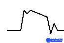
With normal damping, the calibration pulse should have a shape in which the oscillations at the end of the leading and trailing edges amount to about 10% of the pulse amplitude.
To facilitate analysis of the recorded curve, analyzers are used, which may be built into the instrument. Integrators and frequency-analysis devices are most often used. With an integrator, the area lying between the curve under study and the zero line is evaluated, that is, the total bioelectric activity over a given time interval. A frequency-analysis device is a set of narrow-band filters covering the spectrum of the process under study. A stimulator can also be a major part of an instrument for recording bioelectric activity.
1.Sensitivity - this is the ratio of the amount of deflection in millimeters on the recording to the standard voltage applied to the input. The maximum sensitivity of the instrument can range from 1mm/mV (EEG)- 20mm/mV (ECG).
2. The range of measured voltages is determined by the sensitivity, noise level, and nonlinear distortion of the instrument. The minimum deflection on the recording must not be less than 0.5 mm. The maximum deflection must not exceed the limits of the recording width.
3. The amplitude-frequency response of the instrument is determined, in the lower-frequency range, by the parameters of the amplifier, and in the upper range by the parameters of the recorder. This characteristic is changed by feeding sinusoidal signals of equal amplitude and adjustable frequency into the input of the instrument.
4. The range for measuring time intervals is determined by the speed at which the chart tape is fed.
5. The cross-talk coefficient between channels and the synchronism of recording across different channels are determined by feeding a standardized signal into the input of one channel while the others are short-circuited. Deviations from the zero line of the channels with a short-circuited input must not exceed a few percent of the maximum recording amplitude.
+6. Asynchronism of recording is evaluated by comparing the deviations, in millimeters, on the recording in different channels when a DC voltage step is applied to them simultaneously.

Comments