
Lecture
Ultrasonic vibrations in acoustics are understood as vibrations whose frequency lies above the upper limit of audibility of the human ear, i.e. more than 20 kHz. In addition to ordinary sound vibrations, which usually mean longitudinal waves propagating in a medium, bending and shear vibrations, as well as transverse and surface vibrations, are classified as ultrasonic if their frequency exceeds 20 kHz. At present it has become possible to obtain vibrations with a frequency of 1*1010 Hz. The range of ultrasonic vibrations spans roughly 16 octaves. The small wavelength of ultrasonic vibrations in solids has led to the widespread use of ultrasound. Owing to their short wavelength, ultrasonic waves allow excellent focusing and the production of a directed beam. It is therefore possible to speak of ultrasonic rays and to build sound-optical systems on their basis. Relatively simple methods also make it possible to obtain ultrasonic vibrations of comparatively high intensity.
In 1880 the Curies discovered that when certain crystals are stretched or compressed in particular directions, electric charges appear on their surface. Experiments showed that the charge arising from deformation is proportional to the compression or tension of the crystal. The sign of the charge depends on the type of deformation. It reverses when going from compression to tension. The piezoelectric effect was found in crystals of tourmaline, quartz, sodium chlorate, tartaric acid, cane sugar, and Rochelle salt.
From the standpoint of physics and biophysics, when ultrasound interacts with biological media a number of mechanisms of action on body tissues can be distinguished. Thermal mechanisms occur in cases where absorption of acoustic energy leads to a local rise in the temperature of the medium. Here the main contribution to acoustic absorption comes from such scattering-loss mechanisms as molecular relaxation of internal friction and the relative motion of particles of the medium. The parameters of interaction associated with thermal mechanisms are the intensity and duration of exposure.
Cavitation, understood as the process of growth and oscillation of gas bubbles in an acoustic wave field, usually occurs when high-power ultrasound is used in continuous-emission mode. It can also be observed when using diagnostic ultrasound with a small number of cycles per pulse. When studying cavitation it is necessary to know such parameters as the maximum negative pressure and pulse duration, since it is during the rarefaction phase that gas diffuses from solution into the air bubble, causing the latter to grow.
The non-thermal mechanisms of action of ultrasonic vibrations include stationary ones: radiation pressure, the mixing of absorbing ultrasonic liquids due to the occurrence of acoustic streaming, and shear stresses in structures located within acoustic streams in a liquid.
According to data from the American Institute of Ultrasound in Medicine, ultrasonic irradiation has no noticeable biological effect on mammalian tissue at intensities below 100 mW/cm2. At higher intensity levels, clearly expressed biological effects are absent if the product of intensity and exposure time does not exceed 50 J/cm2. Typically the power of continuous-wave ultrasonic Doppler instruments lies within the range of 20 – 800 mW/cm2, the power of pulse-echo scanners is 7*10-2 – 680 mW/cm2, however the radiated acoustic energy flux density of pulse-echo scanners is sometimes as high as 2800 W/cm2. When examining deep-lying structures of the body, low frequencies are used: for the heart – 2,25 – 5 MHz, for gynecology – 3,5 – 5 MHz. For examining shallow structures, higher frequencies are used, so echography of the eye is performed at a frequency of 10 – 15 MHz.
By their principle of operation, ultrasonic instruments are divided into two groups:
Pulse-echo – used for determining analytical structures, visualization and measurement;
Doppler – make it possible to obtain the kinematic characteristics of rapidly occurring processes: blood flow in vessels, contraction of the heart.
+However, this division is conventional. There are systems that make it possible to simultaneously study both analytical and functional parameters.
Three methods of ultrasonic diagnostics have become the most widespread in clinical practice:
one-dimensional studies – echography;
two-dimensional studies – sonography;
Dopplerography.
Two variants are distinguished: the A – method and the M – method. The amplitude of the signal reflected on the screen characterizes the magnitude of reflection, and the delay time relative to the start characterizes the depth of the inhomogeneity, i.e. the distance from the body surface to the tissue that reflected the signal. Thus the one-dimensional method provides information about the distance between tissue layers along the path of the ultrasonic pulse. The A – method is used in the diagnosis of diseases of the brain and heart, and in neurosurgery. Echoencephalography is used to determine the size of the brain ventricles and the position of the midline structures. In cardiology, echocardiography is used to assess the structure of the heart, using the M – method. In the M – method, the transducer remains in a fixed position while the amplitude of the echo signal changes during recording. If the echogram is shifted by a small amount with each successive probing pulse, an image in the form of a curve is obtained – the M – echogram.
Ultrasonic scanning makes it possible to obtain a two-dimensional image – the B – method. The essence of the method consists in moving the ultrasonic beam over the surface of the body during the examination. This ensures the registration of signals one-dimensionally, or sequentially, from many points of the object. The resulting series of signals is used to form an image. In ultrasonic scanning, the brightness of each point is directly proportional to the intensity of the echo signal. A strong echo signal produces a bright light spot on the screen, while a weak one produces various shades of gray up to black. The most important element of an ultrasonic scanner is the intermediate digital processing unit. In it the ultrasonic image is converted into digital form and is accumulated as it arrives from the transducer. The gray-scale gradation range reaches 64 levels. The intermediate digital memory makes it possible to freeze an image of the moving organ.
Dopplerography is based on the Doppler principle, i.e. the frequency of the echo signal reflected from a moving object differs from the frequency of the emitted signal. The source of ultrasonic waves is an ultrasonic transducer; it is stationary and forms a narrow beam of waves. If the organ or object being observed moves, then the frequency of the ultrasonic waves returning to the transducer differs from the frequency of the primary waves. If the object moves toward the stationary sensor, it encounters more ultrasonic waves during the same period of time.
There are two types of Doppler examinations:
continuous-wave;
pulsed.
In the first case, the generation of ultrasonic waves is carried out continuously by one piezoelectric element, while the reflected waves are registered by another. In the electronic unit of the instrument, the two frequencies of the ultrasonic vibrations are compared. The shift in the frequencies of these vibrations is used to judge the activity of movement of analytical structures. Analysis of the frequency shift can be performed acoustically or with the aid of recorders. This method is used effectively in studying blood flow velocities. A drawback of this method is that the change in frequency of the reflected signal occurs not only because of the movement of blood in the vessels, but also because of any moving structures encountered along the path of the ultrasonic wave.
Pulsed Dopplerography makes it possible to measure velocity within a specified region of the sample volume. The dimensions of this volume are a few millimeters in diameter. In some devices, blood flow velocity can be determined in several sample volumes. The results of such examinations can be presented in three ways:
as quantitative indicators of blood flow velocity;
as curves;
as sound signals.
The audio output makes it possible to differentiate homogeneous laminar blood flow by ear. When recorded on paper, laminar blood flow is characterized by a thin homogeneous curve, while turbulent flow is characterized by a wide, non-homogeneous one.
+Dopplerography is used to study the shape, contours and lumens of blood vessels. This makes it possible to detect narrowing and thrombosis of vessels, disturbances of blood flow, and the state of blood circulation.
Combined examination methods are also used, the so-called duplex sonography. In this case both an image of the vessels and a recording of the blood-flow curve are obtained.
Classification of emitters
By type of action:
Emitters for external action.
Emitters for intracavitary action.
Emitters for external and intracavitary action.
Depending on the type of acoustic coupling with the tissue surface:
Acoustic coupling is provided by direct contact of the working surface of the emitter with the tissue.
Acoustic coupling is provided through an intermediate layer of water or medicinal agents between the working surface of the emitter and the tissue.
Depending on the position of the emitter:
Emitters designed for moving the working surface relative to the tissue.
Emitters with a stationary working surface.
Depending on the shape of the working surface:
with a flat working surface;
with a cylindrical working surface.
Depending on the field of application:
A – obstetrics;
G – gynecology;
D – dermatology;
K – cosmetology;
L – laryngology;
O – ophthalmology;
P – proctology;
S – stomatology;
U – urology;
F – general physiology.
By maintenance system:
repairable;
non-repairable.
Designation of emitters.
It consists of the word «emitter» and its code. The code consists of the letters IUT, the numerical value of the frequency at which high-frequency electrical signals are converted into ultrasonic ones, in MHz, the numerical value of the diameter of the cylindrical working surface, in mm, the numerical value of the nominal area, in cm2, the model's serial number, and a conventional designation depending on the field of application.
IUT 0,88 – 2,07 S
IUT 0,88 – 13 – 2,08 U
Technical requirements for emitters.
Emitters must ensure operability at a frequency whose nominal value is selected from the series 0,88 1,76 2,64 5,28 MHz, while the relative deviation of the frequency of the applied high-frequency electrical oscillations must not exceed 0,03%. The nominal value of the effective area of the emitter is selected from the series 0,1 0,2 0,4 0,5 1,0 2,0 4,0 6,0 8,0 10,0 cm2. The relative deviation must not exceed 10%. The diameters of the cylindrical working surface are selected from the series 3 5 7 9 11 13 16 20 mm. The deviation from the nominal value must not exceed 0,3 mm.
Emitters must ensure emission of ultrasonic vibrations with a maximum effective intensity of not less than 1,01 W/cm2.
Requirements for ergonomic and structural characteristics:
The length of the connecting cable must be 1,5 - 1,7 m.
Emitters must bear markings indicating the permissible depth of their immersion in water.
The surfaces must be free of flow marks, cracks, voids, or scratches.
The outer surfaces of the emitters and any fixtures mounted on them must be resistant to disinfection with a 3% solution of hydrogen peroxide with the addition of 0,5% detergent, or with other disinfecting solutions.
Reliability requirements:
Must remain operable after operating for one minute under load, when supplied with high-frequency oscillations corresponding to the emission of ultrasonic vibrations in water with an effective intensity of not less than 0,4 W/cm2.
Must be operable after operating for three cycles in a mode of 15 minutes of emission of ultrasonic vibrations with an effective intensity of not less than 0,4 W/cm2, and 10 minutes without emission.
Safety requirements:
+
The temperature of the working surface of the emitter after operation must not exceed 42 C at an initial water temperature of 25+/-1 C.
The radius of curvature of the working parts of the emitter must not be less than 0,3 mm.
The working parts of the emitters must show no damage.
GOST 25052-87 applies to apparatus for ultrasonic therapy that generate ultrasonic vibrations at frequencies of 0,88 MHz, 1,76 MHz, 2,64 MHz, 5,28 MHz for the purpose of acting on human tissue in the treatment of diseases in medical institutions. This standard does not apply to ultrasonic apparatus for reflexotherapy and aerosol therapy, or to the ultrasonic components of apparatus intended for combined exposure to ultrasound and other forms of energy.
Apparatus for ultrasonic therapy are classified:
1) by the number of frequencies generated and by the number of patients serviced simultaneously:
- single-frequency apparatus for servicing one patient;
- dual-frequency apparatus for servicing one patient;
- dual-frequency apparatus for servicing two patients.
2) by field of application:
A – obstetrics;
G – gynecology;
D – dermatology;
K – cosmetology;
L – laryngology;
O – ophthalmology;
P – proctology;
S – stomatology;
U – urology;
F – general physiology.
Designations of apparatus for ultrasonic therapy.
The designation of the apparatus must consist of the word "apparatus" and the code of the apparatus. The code of the apparatus consists of the letters UZT, a conventional designation of the frequency or frequencies, the model's serial number, and a letter designation of the type of apparatus. The conventional designation of the frequency or frequencies must, for apparatus of the first type, consist of a digit corresponding to the conventional designation of their frequency, where 1 = 0,88 MHz, 2 = 1,76 MHz, 3 = 2,64 MHz, 6 = 5,28 MHz. For apparatus of the second and third types, the conventional designation of the frequency consists of two digits; for apparatus of the second type the digits are arranged in ascending order of their values, while for apparatus of the third type – in descending order.
Apparatus UZT – 1.02 S (type 1; 0,88 MHz)
Apparatus UZT – 13.02 S (type 2; 0,88 MHz; 2,64 MHz)
Apparatus UZT – 31.02 S (type 3; 2,64 MHz; 0,88 MHz)
Apparatus must ensure the generation of ultrasonic vibrations with an effective intensity whose nominal value is selected from the series 0,05 0,1 and so on in steps of 0,1 up to 1 W/cm2. The relative deviation of the maximum value of the effective intensity of ultrasonic vibrations must be no more than +/- 35% of the maximum value.
The names of the values of pulse parameters when operating in pulsed mode must be as follows: the pulse repetition frequency equals the frequency of the mains supply; the nominal value of pulse duration may be 1 ms, 2 ms, 4 ms or 10 ms; the deviation of pulse duration from that stated in the data sheet must be no more than +/- 20%; the deviation of the rise and fall time must be no more than +/- 5%; the non-uniformity of the pulse top must be no more than +/- 10%; the lower limit for setting the procedure duration must be no more than 3 minutes, the upper limit – not less than 15 minutes; the timer error – +/- 30 seconds; after the procedure ends, the duration of the sound signal must be not less than 5 seconds.
To carry out verification of the metrological characteristics of the apparatus, the following instruments must be used:
An AC wattmeter (220 V nominal), whose upper measurement range limit is not less than 100 W, accuracy class not lower than the second.
An AC voltmeter, whose upper limit is not less than 250 V, accuracy class not lower than 1,5.
A high-frequency voltmeter, whose upper limit is 1 – 100 V, accuracy class not lower than 1,5; frequencies up to 6 MHz.
A test tank, whose internal dimensions are 500x260x230 mm, with an ultrasonic vibration attenuation coefficient of not less than 30 dB.
An oscilloscope, whose bandwidth is not less than 20 MHz, input resistance 1,1 MOhm, accuracy class 2.
An electronic-counting frequency meter, whose upper limit is not less than 6 MHz, accuracy +/- 1 Hz.
Characteristics to be verified:
- frequency of the ultrasonic vibrations generated by the apparatus;
- intensity of vibrations;
- ability of the apparatus to operate within a supply voltage range of 198-242 V;
- verification of the apparatus's operation with emitters not included in the apparatus's kit;
- verification of the settable procedure durations;
- verification of the duration of the sound signal;
- verification of resistance to environmental factors;
- verification of resistance to mechanical effects;
- verification of durability and mean time between failures.
Verification of the pulse repetition frequency is carried out using a frequency meter.
Graphs
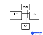
Verification of the procedure duration is carried out by setting the maximum and minimum procedure time, with the time measured using a stopwatch.
+Verification of the device's ability to operate within a given range of supply voltages is carried out using a Latr (variac) (fig.)
The following instrumentation is used:
An electronic-counting frequency meter operating in the range 10 Hz – 1 MHz.
A cathode-ray oscilloscope with a bandwidth of 0 – 1 MHz, an input resistance of up to 1 MOhm, and a measurement error no worse than 10%.
A dual-beam oscilloscope with a bandwidth of up to 200 kHz, an input resistance no worse than 0,5 MOhm, and an amplitude measurement error of +/-10%.
A signal generator with a frequency range of 0,01 Hz – 100 kHz, a frequency-setting error of 1x10⁻⁶, and an output voltage of not less than 1 V.
An AC voltmeter, rated for a voltage of 20 mV – 100 V, frequency 20 Hz – 1 GHz.
A total harmonic distortion meter, designed to operate with an input voltage of 100 mV – 100 V, whose voltmeter frequency range is 20 Hz – 200 kHz, voltage measurement error 4%.
A milliammeter, whose frequency range is 40 Hz – 40 kHz, current measurement 0,03 – 1000 mA.
Performing the verification:
1) External inspection.
2) Testing – the controls are checked, the possibility of setting mechanical and electrical zero.
3) Determination of metrological parameters:
- determination of the frequency error produced by the frequency meter, and at low repetition frequencies by the same frequency meter in period-measurement mode. In this case the error is determined as a percentage
δ = (fn + fa) / fa * 100%
where fn – fnominal – nominal value of the frequency,
fa – factual – actual value of the frequency.
The error must be checked at not less than three points of the range – at the two extremes and one intermediate point.
- determination of the error in setting the pulse duration produced by the frequency meter. It must be determined at all fixed duration values and at not less than three points of the range.
4) Determination of the duration of the pulse rise and fall time, produced using an oscilloscope. The reading is taken from the 0,1 level to the 0,9 level of the signal amplitude.
5) The relative value of the droop of the flat top of the pulse is determined by measuring the absolute values of the parameters in units of length on the oscilloscope screen and is calculated using the formula:
δdr = (hdr / hp) * 100%
+where hdr – top droop,
hp – pulse droop.

Comments