
Lecture
Structurally, an ultrasound transducer (probe) consists of a scanning head, a cable and a connector.
1 - the acoustic lens, designed to shape the geometry of the acoustic beam. The lens is made of a special plastic, is in direct contact with the gel and the patient's body, and can be of various colours (often grey, blue or red).
2 - the matching layers, designed for efficient penetration of acoustic waves. They are a combination of various polymer materials.
3 - the piezocrystal array, designed to emit ultrasound waves. This is made possible by the piezoelectric effect.
The nature of the crystals of the piezoelectric elements allows them to generate high-frequency sound under the action of electrical voltage. Conversely, when placed in a field of high-frequency sound vibrations, a piezocrystal generates electrical energy. By including such crystals in an electrical circuit and processing, in a certain way, the signals received from them, we can obtain an image on the ultrasound machine's screen.
4 - the damper (backing) made of a solid material, designed to eliminate excessive vibrations in order to shorten the pulse length and increase resolution.
5 - the plastic housing with a flexible end section
6 - the coupling - a rubber sleeve to prevent the cable from kinking and being damaged where it exits the probe housing.
Watch the video on the structure of an ultrasound probe, where we not only explain but also show a probe in cross-section!
Given such a complex structure, a probe can develop the most varied problems: defects of the lens, housing, cable or connector, and even faults in the internal electronics, but thanks to our experience and our own developments in this field we can restore an ultrasound probe with damage of any complexity.
Subscribe to our newsletter, where you will receive interesting articles about ultrasound, ultrasound probes and other up-to-date information from the medical field.
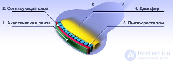
The nature of the crystals of the piezoelectric elements allows them to generate high-frequency sound under the action of electrical voltage. Conversely, when placed in a field of high-frequency sound vibrations, a piezocrystal generates electrical energy. By including such crystals in an electrical circuit and processing, in a certain way, the signals received from them, we can see an image on the ultrasound machine's screen.
Between the probe's crystal array and the patient's body there are a number of matching materials for better penetration and additional focusing of the ultrasound beam. These are the probe's own matching layers, the acoustic lens and the coupling acoustic gel.
It should be remembered that only gel from the list recommended by the manufacturer should be used, since gels differ in their physical parameters. Using the “wrong” gel will lead to overheating of the piezocrystal array, the matching layers and the lens, as well as to increased load on the electronic units that generate high voltage and amplify the received signal.
Thus, the seeming lack of justification and the savings from using a cheaper gel will lead to the probe breaking down and to costly repair of the machine itself, and in some cases even to electrical injury to the patient or physician, since high electrical voltage is applied to the probe head.
If you nevertheless have a problem with a probe, don't be in a hurry to write it off:
Despite all its complexity, repair of ultrasound probes is possible in practically any case.
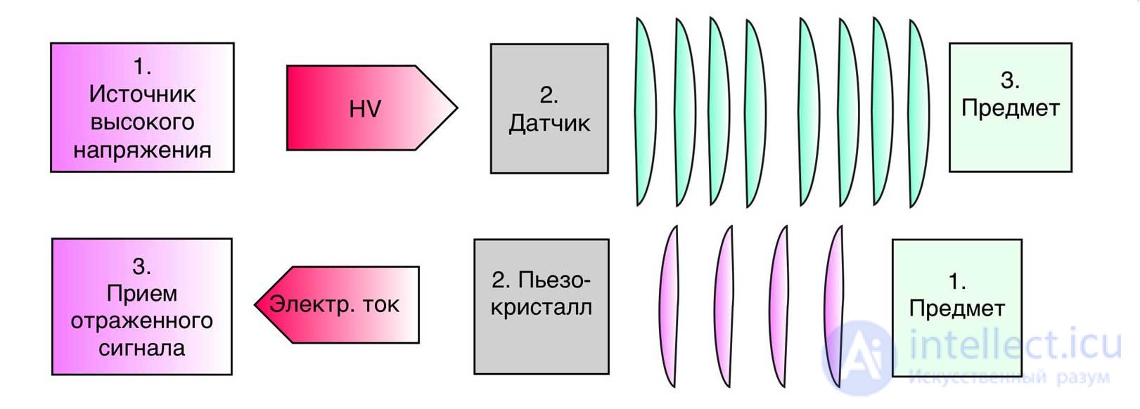
A short pulse is sent into the tissue through the ultrasound piezoelectric transducer.
It propagates and is reflected from objects located at different depths. The speed of ultrasound propagation in tissue is known, so the distance to the object that reflected the given echo signal can be determined.
The amplitude of the received signal is coded on the screen using shades of grey. The human eye is most sensitive precisely to shades of grey. This is how the amplitude of the received signal is coded into brightness on the ultrasound scanner's monitor.
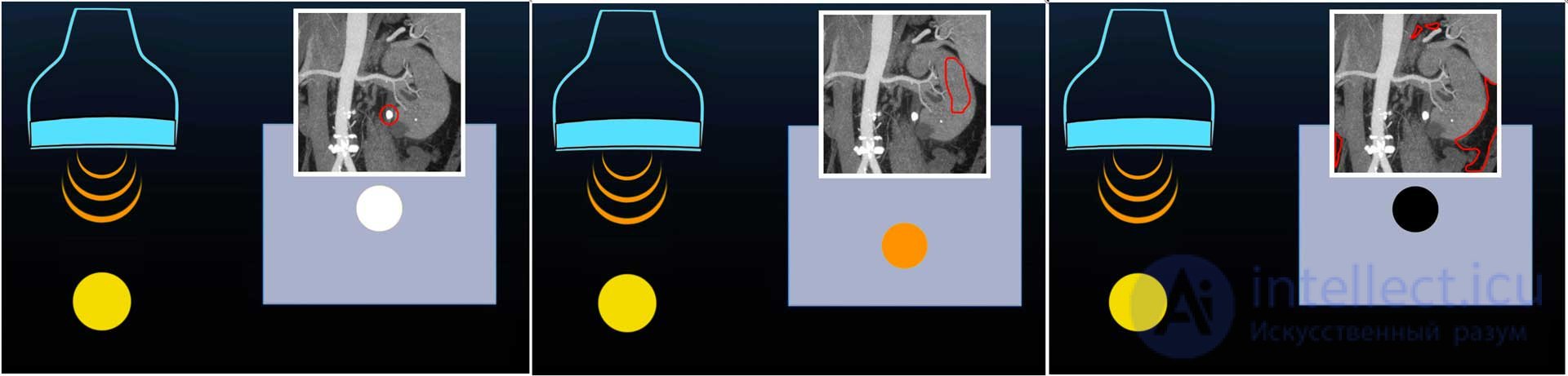
In this respect, the operation of the ultrasound probe from the user's point of view amounts to the following:
solid objects look brighter, almost white, while cavities, on the contrary, look black.
This happens because the amplitude of the signal reflected from bone is high. If the beam is instead directed into a cavity (a void), the ultrasound beam will travel very deep, will be strongly attenuated, and the amplitude of the received reflected signal will be close to zero. Biological tissues, which are of greatest interest to the physician, are displayed on the machine's screen in intermediate shades of grey.
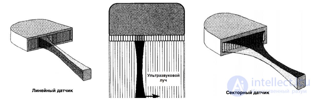
In linear and convex probes the piezocrystals emit in groups, one after another, until all the crystals from the beginning of the piezocrystal array to the end have fired. One frame on the display is refreshed once all the groups have sent and received the ultrasound signal in turn.
In sector phased-array probes, all the crystals emit almost simultaneously. Small electronic signal delays are deliberately introduced for each crystal in order to steer the scanning beam. The image on the display is refreshed once the beam has scanned the entire sector of view.
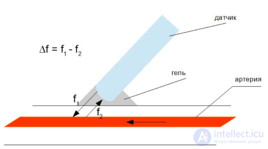
Let us consider one of the types of Doppler – the continuous-wave Doppler mode. The essence of the method lies in the application of the Doppler effect.
Sound changes its frequency when it is reflected from a moving object. Depending on the direction of the object's motion and its speed, this difference, or frequency shift, is called the Doppler shift. It will change over time.
In this mode, one half of the probe's crystals works on emitting ultrasound, while the other half works on receiving it. By comparing the received signal with the transmitted one, we obtain the Doppler frequency shift of the ultrasound.
From the value of the shift, the speed of motion of tissues or fluids in the body can be calculated. The Doppler shift often lies within the range of frequencies audible to humans (20Hz-20kHz), which is why it is output as sound, through the machine's speaker, as an additional source of information.
There are also other operating modes of the ultrasound scanner, in which the operation of the probe differs from those described above, both in software and in hardware terms.
For all types of probes, the main parameters and characteristics, description and areas of application are given. Let us consider the main (typical) faults and breakdowns of each type and the repair of ultrasound probes.
Each type of probe of a modern ultrasound machine has a number of characteristics:
Brochures, promotional materials and even manufacturers' and suppliers' websites do not always list all these parameters and characteristics. Some of them are not relevant for certain types of probes (you may also come across the term ultrasound transducer from the English "transducer" - probe). It is certainly important to pay attention to the frequency (frequencies) of the probe, but besides this it is always necessary to take into account the areas of application and the compatible operating modes, since frequency alone does not carry exhaustive information about a specific probe.
You may also come across the name abdominal probe (due to its main area of application)
The frequency of probes of this type usually ranges from 2 to 7.5 MHz, and in some machines the probe's operating frequencies may be even higher. Many probe models can work with so-called harmonics, which makes the imaging of higher quality in many types of examinations.
The penetration depth of probes of this type is about 25 cm, which is quite sufficient for all its areas of application. The dimensions of the displayed image of the organ being examined are a few centimetres wider than the probe itself, i.e. convex probes have a relatively wide field of view.
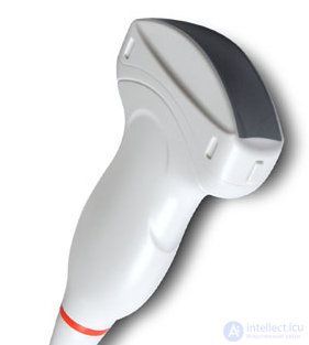
Ultrasound probes of this type are used to examine deeply located objects: abdominal examinations (general examinations of the abdominal cavity), hip joints, the reproductive system and others. That is, convex probes are used both in general practice, in obstetrics and gynaecology, and in other fields.
The convex probe is supplied with most modern ultrasound machines. It can, of course, be absent in some cases, but it is practically impossible to imagine a general-purpose, wide-profile ultrasound scanner without an abdominal convex probe.
Common faults of this type of ultrasound probe:
In its design, this probe is identical to a convex one; the only difference is that the microconvex probe is smaller in size.
It is used, as a rule, for the same examinations, but only in paediatrics.
In terms of technical parameters, the radius of curvature of the scanning module of a microconvex probe is greater, since the module itself is smaller in size.
The operating frequencies generally correspond to those of ordinary convex probes, but may be higher, since the microconvex type of probe does not require such high penetration capability.
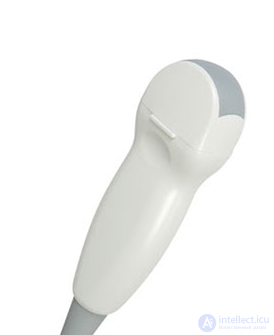
The frequency of this type of ultrasound probe ranges from 5 to 15 MHz. The scanning depth is no more than 11 cm. The main feature of a linear probe is the full proportionality of the object being examined to the position of the linear ultrasound probe, but the difficulty is that it is impossible to ensure that the ultrasound probe fully fits against the surfaces being examined. These probes are used for examining superficial structures, such as the mammary gland, the thyroid gland, small joints and muscles, and for examining vessels.
Common faults of this type of ultrasound probe:
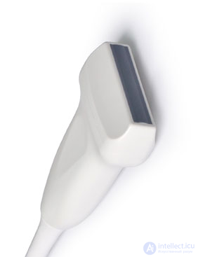
The frequency of this type of probe ranges from 1.5 to 5 MHz. It is used for situations where it is necessary to obtain a wide view of a small area. It is mainly used for viewing the heart and the intercostal spaces.
Common problems with sector probes:
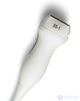
This type of probe is actively used in cardiology. With the help of a sector array it becomes possible to adjust the angle of the ultrasound beam in the scanning zone, which makes it possible to look behind the fontanelle, the ribs or the eyes.
The probe is able to work in PW and CW mode, because it has the ability to receive and transmit independently with different parts of the phased array.
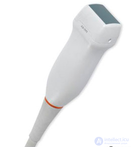
This type of probe is used for examinations of the pelvic organs: obstetrics, gynaecology, urology.
This group includes vaginal, transrectal and recto-vaginal ultrasound probes.
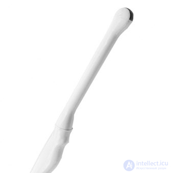
Biplane ultrasound probes have several transducer elements.
With their help it is possible to obtain images in longitudinal and transverse sections.
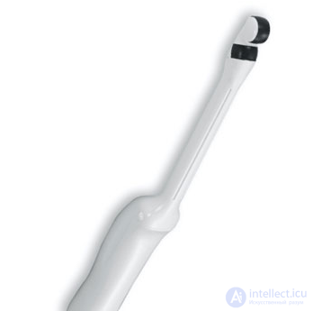
This type of probe is used to obtain three-dimensional images.
Such imaging is made possible thanks to a probe that rotates (swings from side to side) inside a dome.
The following problems are most often encountered with 3D/4D probes:
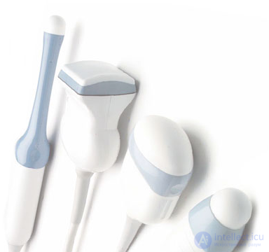
These probes can be divided into one-and-a-half-dimensional and two-dimensional.
One-and-a-half-dimensional matrix probes make it possible to obtain maximum resolution in the thickness (elevation) direction
Two-dimensional probes make it possible to obtain a volumetric image in real time and display a certain number of projections and slices on the screen.
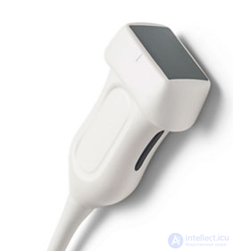
This type of probe involves separating the receiver and the transmitter.
It is used for examining the arteries and veins of the legs and neck.

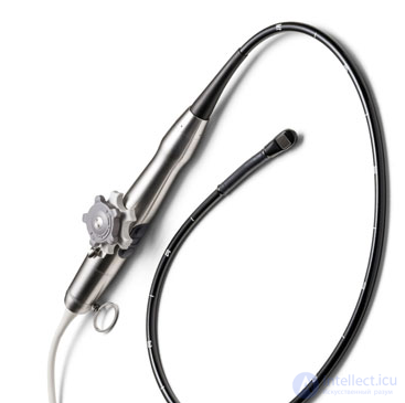
Transesophageal ultrasound probes.
This type of probe is used for transesophageal echocardiography. The fairly complex design of this probe is developed for specific examinations.
The operating frequency of this type of probe is from 2.5 to 10 MHz.
Main faults of these probes:
Cavitary ultrasound probes are used in obstetrics, gynaecology and urology.
Cavitary probes include:
As a rule, the difference between these types of probes is the angle (curvature) of the scanning module.
For transvaginal probes the curvature is 8-10mm, for transrectal probes - 10-14mm.
Manufacturers produce both 2D and 3D types of cavitary ultrasound probes.
With the help of a small radius it is possible to obtain a complete picture of the internal organs, although the area of the piezoelements in this type of ultrasound probe is quite small.
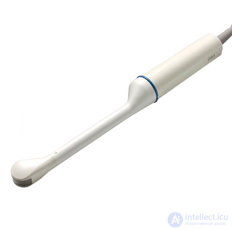
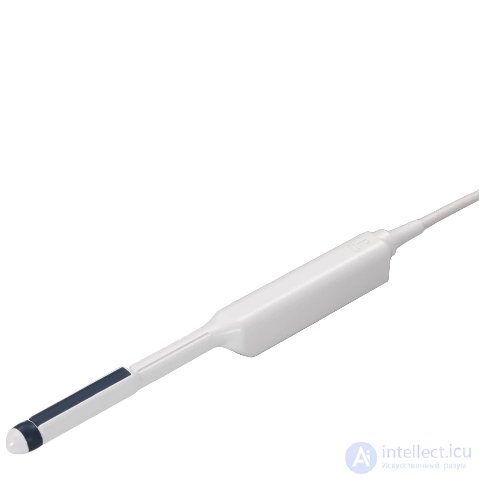
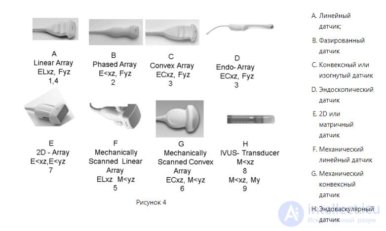
Fig. 3 and 4 make it possible to systematically organize image formats, to group them by types and models of probes, further taking into account the scanning variants, the choice of modes and specific planes.
To classify transducer formats, abbreviations describing certain relationships between the graphics and the transducer are often combined.
Definition by type of scanning process:
M — mechanical;
E — electronic;
F — fixed, no scanning.
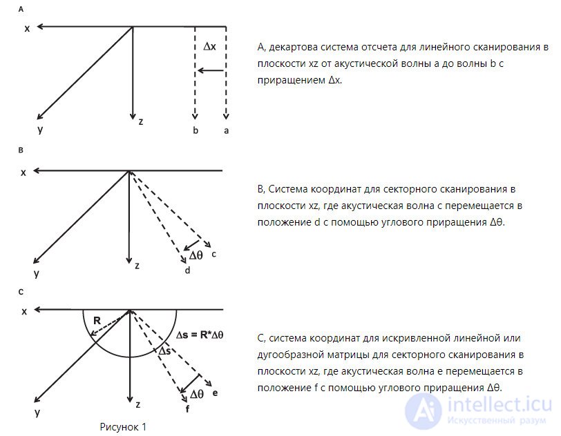
Scanning process by direction:
L — linear;
< — angular;
C — curved;
combinations of directions.
This contributes to precise determination of the plane being scanned. To obtain results in a two-dimensional format, the XZ plane is used.
Based on the descriptions given, all transducers can be associated with various types of scanning and planes.
Thus, in figure 4a one can see:
This makes it possible to shorten the final designations: the combinations ELxz and Fyz correspond to formats 1 and 4 in diagram 3.
The combined type — fig. 1 in fig. 3. The trapezoidal type is denoted by the number 4 in fig. 2. It represents a rectangular format having two partial sectors at the ends for a linear array in diagram 4a.
The phased-array type shown in fig. 4b is associated with the sector-type format 2, located in diagram 3, and with the preceding planes.
In fig. 3 and 4 one can review all the transducers and formats, and the types of probes — in diagram 5.
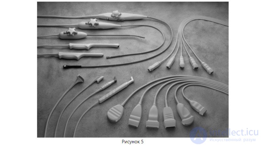
Family of probes:
Upper left square: the three upper probes are transesophageal; the two lower ones are endovaginal.
Upper right square: a microconvex probe in the centre and two phased-array probes on each side.
Lower right square, left to right: a convex probe, three linear probes, a curved linear probe, a phased-array probe.
Lower left square, left to right: two surgical probes and two intraoperative probes.
The curved/convex variant of probes is similar to the linear format. The difference is that the components are arranged on a curved surface rather than a linear one. This format is similar to a sector of a circle, or a slice of cake without the top, and is described in detail as the field of view (FOV). This determines its lateral angular arrangement. In the example given, the electronic variant of linear scanning E in the XZ plane and fixed focus F in the YZ region were used. In abbreviated form this looks like: ECxz and Fyz in format 3 in fig. 4b.
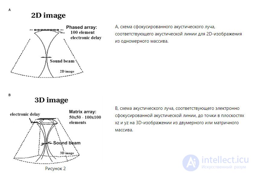
Three-dimensional imaging is becoming increasingly popular and relevant. For this reason it is important to know all the details and particulars. In the three-dimensional variant, it is not a plane but a volume that is scanned. This can be seen from the outline in fig. 2b. When using a two-dimensional or matrix-type array, scanning is angular in two directions and is electronic in nature. Such a scanning volume is represented by a pyramidal shape — in fig. 7, figure 3.
Electronic-type focusing is located in two planes with an angular scanning variant. The designation and image format is of the “E” type.
To obtain an alternative, cost-effective three-dimensional image, linear- and convex-type arrays are mechanically scanned in the region of the X axis in the YZ plane. In this variant, the arrays move inside acoustically transparent chambers filled with liquid. Thus, a linear-type array (A) rotates around the Z axis to create a series of images in the plane (in the form of format 1 or 4). As a result we obtain a mechanical-type scanning transducer of type F, illustrated in figure 4, as well as a volumetric image 5 in fig. 3.
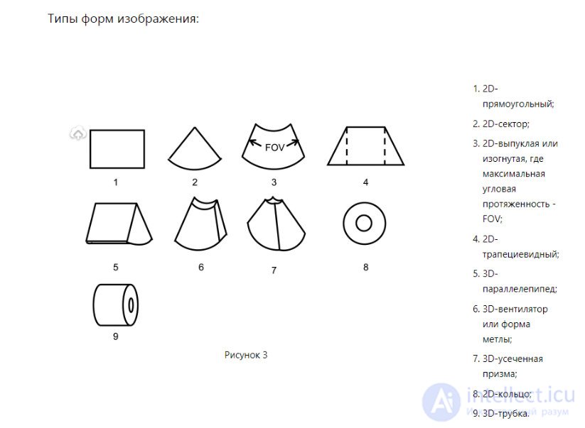
In exactly the same way, a curvilinear or convex-type array (C) is rotated around an axis to form several flat image shapes (3). As a result we obtain the mechanical variant of probe G, shown on chart 4, and volumetric image 6 — in fig. 3.
For a complete picture, the electronically controlled movement of a one-dimensional array (A, B, C) can be moved mechanically in a manual, free-hand three-dimensional mode. The resulting picture is assembled into a three-dimensional volume.
Note that the change in the image for this mode assumes a fixed interval value or spatial data for each type of plane in the spatial imaging format. This is achieved with the help of position sensors.
The results of examinations obtained using single-element transducers, used for the intraluminal or catheter approach (intravascular or intracardiac ultrasound), are shown in illustrations 8 and 9, fig. 3.
The probe shown in fig. 4n is able to perform mechanical scanning to obtain two- and three-dimensional results, as demonstrated in fig. 8-9, fig. 3.
For format 8 the probe (in fig. 4n) is moved at an angle over the entire area of the circle to obtain a picture in the shape of a doughnut. There is also a matrix variant of this endovascular ultrasound device. When the mechanical-type transducer is rotated and moved along the Y axis, an image is formed in a cylindrical volumetric variant, format 9 (fig.3)
All the transducer variants shown in fig. 4 are matched to different image formats, as in fig. 3, using the formats and designations in the scanning process of the given transducer (fig.4).

Comments