
Lecture
Biostimulators and devices for affecting biologically active points
Fluctuorization — the therapeutic application of alternating, partially rectified, or rectified low-voltage current with chaotically varying frequency (up to 2000 Hz) and amplitude. The use of these oscillations, primarily for dental practice, was proposed in 1960 by A. R. Rubin.
The method uses voltage oscillations with a noise spectrum, i.e., with aperiodic changes in the oscillation frequency ranging from 100 to 2000 Hz, voltage — from 0 to 100 V, and current density — up to 3 mA/cm2.
Commercially manufactured fluctuorization devices generate the following three types of voltage oscillations:
Mechanisms of therapeutic action. The differing physical properties determine the different effect of each type of oscillation. Symmetrical oscillations have the weakest excitatory effect, since changes in ion concentration at semipermeable membranes are to some extent smoothed out by identical changes in ion concentration occurring in the opposite direction when the current direction changes. The excitatory effect at any given moment is determined by the oscillation frequency, and consequently, by the duration and amplitude of the oscillation. At the same amplitude, the excitatory effect noticeably increases as the oscillation frequency decreases. Since the values of these parameters change randomly, moments of strong excitation also occur chaotically. Their intensity can be regulated only by the magnitude of the current. Under such conditions, on electrodes of equal area, the excitatory effect under each of them is the same. The effect under one of the electrodes is enhanced by a corresponding reduction of its size. The aperiodic occurrence of excitation peaks increases the irritating effect and reduces adaptation compared with the effect of periodic oscillations of the same amplitude. Therefore, in cases of pronounced inflammatory processes, this mode should be avoided because of the possibility of exacerbating the process. We have observed such phenomena when using interference currents with aperiodic beat sequences.
Partially rectified oscillations, with the same disorderliness in the timing of peak occurrence, produce a stronger excitatory effect under the electrode connected to the negative terminal of the device. All reactions to the action of these currents are more pronounced under the negative electrode. These reactions manifest, at suprathreshold current strength, as arrhythmic fibrillations of muscle fibers, which turn into irregular muscle twitching as the current strength increases further. In this case, blood circulation improves in the tissues under the electrode and the temperature rises somewhat. This increase, caused by the revival of blood circulation, persists for 40—60 minutes after exposure. Excitation of a large number of nerve and muscle fibers in the zone of current passage creates massive proprioceptive impulses to the central nervous system, leading to pain relief, as with other pulsed currents.
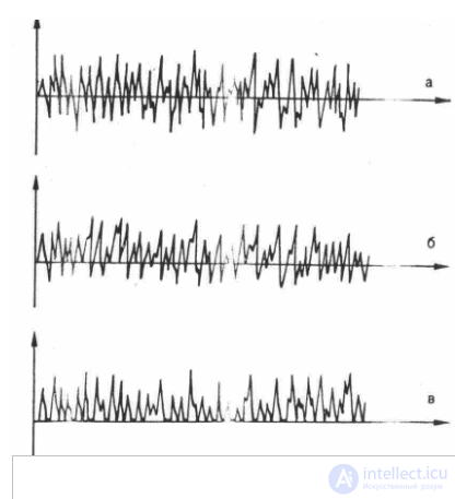
Fig. 1. Graphic representation of fluctuating currents.
a – alternating symmetrical current; b – alternating asymmetrical current, c – rectified current.
Improved blood and lymph circulation, activation of leukocyte phagocytic activity, and reduction of pain manifestations provide the anti-inflammatory effect of fluctuating currents
Rectified oscillations are essentially a constant pulsating current with pulsations that vary chaotically in frequency and amplitude. Therefore, in addition to the effects possessed by non-rectified and partially rectified oscillations, the application of rectified fluctuating currents also exhibits the effect of a constant component, resembling the influence of galvanic current. Overall, the effects of rectified fluctuating oscillations are close to those of diadynamic currents. The difference lies only in the fact that with rectified fluctuating oscillations, the excitation caused by the peak values of the current, and the sensations associated with it, are not rhythmic as with diadynamic currents, but chaotic, which makes their excitatory effect stronger. The constant direction of this form of current also allows it to be used for medicinal electrophoresis, in which the action of the current is enhanced by the corresponding medicinal substance.
Technique for performing the procedures. Fluctuorization, like exposure to other pulsed currents, is carried out through contact electrodes. Depending on the purpose of the exposure, one of them may be placed inside the tooth, on the gum, on the mucous membrane, or on the skin surface. The second electrode, usually larger — 8x10 cm, is most often placed on the cervical spine. The intensity of exposure is set according to the patient's sensation. Three degrees of intensity are distinguished. At a weak degree of intensity, a slight vibration and tingling are felt under the smaller electrode. This corresponds to a current density of up to 1 mA/cm2. The medium degree is characterized by weak twitching of the superficial muscles. This corresponds to a current density of 1—2 mA/cm2. At high intensity of exposure, pronounced twitching of the superficial and deep muscles is visible. It corresponds to a density above 2 mA/cm2.
The duration of exposure, depending on the specific conditions, ranges from 5 to 15 minutes, with a course of treatment consisting of 3-15 procedures, performed daily or every other day.
Indications: conditions after surgical treatment for acute purulent inflammatory processes, acute and chronic exacerbated arthritis of the temporomandibular joint, neuralgia, glossalgia, alveolitis, pain after tooth filling, and other similar conditions.
Contraindications: malignant neoplasms, bleeding, stage III hypertension, Meniere's syndrome.
In 1963, a device for treatment with these currents, the «Amplipulse», was developed. Thus, the method of amplipulse therapy consists in the therapeutic application of sinusoidal modulated currents to the body
The currents used in this method are alternating' sinusoidal, with a frequency in the range of 2—5 kHz, amplitude-modulated by low frequencies ranging from 10 to 150 Hz. As a result of the modulation, which consists of a periodic increase and decrease in the amplitude of the current oscillations at a frequency of 2—5 kHz, separate series of current oscillations are formed, so to speak — amplitude pulsations (fig. 1), resembling the beats that arise in tissues during the interference of two currents. However, there is a significant difference between pulsations and beats. It lies in the fact that beats transition into one another without any pauses, or even in the presence of small transitional current values, which gives the action of current beats on tissue a continuous character. This reduces their excitatory effect and promotes the tissues' habituation to them.
With the amplitude modulation carried out in amplipulse therapy devices, series of current oscillations at a frequency of 2—5 kHz are separated from each other by intervals with zero amplitude. The effect of such series of oscillations on tissue is intermittent in nature, which significantly increases their excitatory effect and reduces the body's habituation to them.
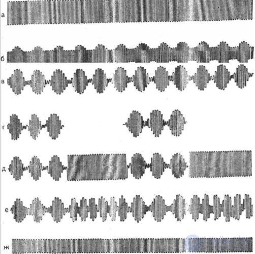
Fig. 1. Graphic representation of sinusoidal modulated currents generated by «Amplipulse» devices
First operating mode (continuous modulation), I RM (CM), a – unmodulated (zero modulation) oscillations – carrier frequency; b – incomplete, about 50% modulation depth; c – complete – 100% modulation depth; d – second operating mode (bursts-pauses), II RM (BP) – alternation of bursts of modulated current oscillations with pauses; e – third operating mode, alternation of bursts of modulated oscillations with bursts of unmodulated oscillations, III RM (BU); f – fourth operating mode (variable frequency), RM (VF) – alternation of current bursts with different modulation frequency; g – the same types of modulation in rectified mode.
In wide-spectrum devices of the «Amplipulse» type, the carrier frequency of 5000 Hz, modulated by a low frequency, is also subjected to three additional types of modulation, which together provide a set of currents for the four operating modes (RM) of the devices. In I RM, the 5000 Hz carrier frequency is modulated by a single frequency selected from the 10—150 Hz range (see fig. 1, b, c). This type is also called continuous modulation, «CM». In II RM (see fig. 1, d), bursts of sinusoidal current modulated at a certain frequency within 10—150 Hz alternate with pauses (bursts—pauses — «BP»). The duration of the current bursts and pauses can be adjusted discretely and separately within a range of 1 to 5—6 s. In III RM (see fig. 1, e), bursts of current modulated at a certain frequency within 10—150 Hz alternate (G with bursts of unmodulated current at a frequency of 5000 Hz (bursts—carrier — «BU»). The duration of the bursts can be adjusted discretely and separately within a range of 1 to 5—6 s. In IV RM (see fig. 13, f), an alternation of current bursts with different modulation frequencies is carried out. In one of the bursts, the modulation frequency is selected from the 10—150 Hz range, while in the second, the modulation frequency remains constant —150 Hz (alternating frequencies — «VF»).
In all the operating modes listed, the modulation depth can be changed from 0 to 100% (see fig. 1, a, b, c) and beyond. This makes it possible, at the same current strength, to change the intensity of the excitatory effect (fig. 14). At a modulation depth of 100%, the amplitude between series of oscillations reaches
zero value; at a modulation depth exceeding 100%, the intervals between series of oscillations with a zero amplitude value are widened, and the excitatory effect at the same amplitude becomes particularly pronounced.
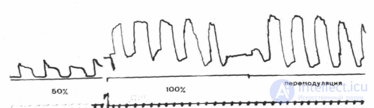
Fig. 2. Amplitude of gastrocnemius muscle contractions induced by SMT at an intensity of 11 mA at different modulation depths.
a – at a modulation depth of 5%, b — at a modulation depth of 100%, c— at a modulation depth exceeding 100% (overmodulation).
Mechanisms of therapeutic action. Sinusoidal modulated currents, being based on an alternating current of increased frequency — 5000 Hz, like interference currents, pass freely through the skin, almost without being absorbed in it. As a result, they do not have an irritating effect on the skin and do not cause the associated unpleasant sensations under the electrodes. Vascular reactions in the skin are also not excited.
Absorption of SMT energy occurs in the more deeply located tissues along the entire path of current passage.
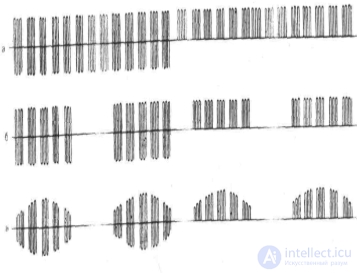
Fig. 3. Graphic representation of sinusoidal modulated currents
generated by devices of the «Stimul» type.
However, since the highest current density forms in tissues located closer to the electrodes (before the current has branched out through the entire mass of tissue), the most pronounced reactions occur in the muscle layer. Nerve and muscle fibers are the most sensitive to SMT. The nature of the sensations is determined by the parameters of the current, namely — the modulation frequency. It is selected so that the frequency of the current oscillation series acting on the nerves and muscle fibers is close to the frequency of nerve action potentials, i.e., the frequency of the natural stimuli that bring a muscle into a state of excitation in health and disease.
A frequency of 5000 Hz ensures free passage of the current through the skin, while modulation with frequencies of 10—150 Hz provides the excitatory effect of the current on nerve and muscle fibers.
At a low modulation frequency, the series of oscillations act like pulses of direct current, causing single contractions of muscle fibers. As the modulation frequency increases, the sensations take on the character of «coarse», «diffuse» vibration, and then «fine», but deeper, vibration. An increase in modulation depth, which effectively widens the intervals with zero or ineffective amplitude, leads, as revealed in our studies, to an intensification of the excitatory effect and vibration sensations, although the average current strength decreases in the process. At significant SMT intensity, tetanic muscle contractions are induced.
No direct data revealing the primary mechanisms of the excitatory action of SMT on excitable structures have been noted in the literature. However, it appears that the ion-membrane theory, which we referred to when examining the mechanism of the primary excitatory action of galvanic current, can also be applied here to explain this phenomenon. However, in this case, the alternating nature of the current and the action of a series of oscillations rather than a single pulse require additions. First of all, one may assume that the excitatory effect on cells with electrically excitable membranes (neuron, nerve and muscle fibers) is produced not by all the oscillations of the series, but only by those of them that have a sufficiently large amplitude. These oscillations, by causing a change in the ratio of ions at the cell membrane, lead to its depolarization and the spread of excitation through the cell. This process lasts thousandths of a second, i.e., a time commensurate with the duration of each oscillation. Then, as a result of the operation of the potassium-sodium pump, a process of repolarization follows again; after another thousandth of a second, the next current oscillation sustains the still-unfinished excitation of the cell. The remaining oscillations with maximum amplitude in the series act in the same way. During the pauses between series of oscillations, the cell's original state is restored. In this case, the greater the pause between series, the more fully the cell's original state is restored, and the more vigorous the reactions to the next series of oscillations.
On the other hand, the lower the modulation frequency, the longer the duration of the current oscillation series, and the stronger their excitatory effect. In this case, not only rapidly responding but also slowly responding excitable structures are involved in the excitation. As the modulation frequency increases and the duration of the oscillation series decreases, the excitatory effect of the current decreases. It is then realized predominantly by rapidly responding structures.
Since the biological, and consequently the therapeutic, effect of sinusoidal modulated currents is provided and determined by the character of the low-frequency modulation, these currents, despite having a carrier frequency of 5000 Hz, are more correctly classified among the methods of low-frequency electrotherapy.
The therapeutic effect of SMT is formed from the reactions of various organs and systems to the above-mentioned excitation of nerves (sensory and motor), receptors, muscle fibers, and, to a significant extent, proprioceptors.
First of all, the activation of blood circulation should be noted. It is achieved mainly reflexively and as a result of the direct action of the current on sensory and autonomic nerve fibers, as well as due to the reflex enhancement of blood supply to the muscle fibers excited by the current. Depending on the location of exposure, activation of blood circulation can be achieved in any organs and tissues. In particular, under the influence of SMT exposure to the collar zone in patients with hypertension with initial manifestations of cerebral vascular atherosclerosis, L. A. Komarova and V. V. Kiryanova (1977) noted normalization of cerebral vascular blood filling, and a decrease or normalization of the initially elevated or unstable vascular tone. As a result of a course of therapeutic SMT exposure, along with a decrease in elevated arterial blood pressure and a slowing of the heart rate, the blood filling and tone of the cerebral vessels were normalized.
According to L. L. Kunitsina, N. P. Leshchinskaya, et al. (1983), in patients with cerebral atherosclerosis, as well as in persons suffering from hypertension, already within 30 minutes after SMT exposure to the sinocarotid and collar zones, the initially elevated tone of the cerebral vessels decreased, an increase in pulse blood filling occurred, venous outflow improved, and a tendency toward a decrease in arterial blood pressure was noted.
P. P. Bagdasarov (1983), as a result of a course of therapeutic SMT exposure to the region of the cervical sympathetic ganglia and the paretic nerves of patients who had suffered a cerebrovascular stroke, noted a decrease in the elevated rheographic index, a reduction in the asymmetry of cerebral blood circulation, and improved venous outflow, alongside an improvement in the patients' general condition, a reduction in headaches, an increase in the strength and range of motion of the paretic limb muscles, and a decrease in elevated muscle tone.
A. V. Vorotyntseva, N. I. Strelkova (1977), in treating patients with parkinsonism as a result of SMT exposure to the cervical, upper and lower thoracic, and also upper lumbar segments of the spine with paravertebral electrode placement, observed improvement of cerebral circulation, stimulation of the sympathetic-adrenal system, increase in its reserve capacity, reduction of muscle hypertonus, |reduction of tremor.
E. M. Orekhova, Al-Saig Fathi (1983), in treating patients with hypertensive disease as a result of SMT exposure with orbital-occipital electrode placement, also observed improvement of arterial inflow and venous outflow according to REG data, a decrease in arterial pressure, cessation of headaches, and improvement in general well-being. Improvement of cerebral circulation with SMT exposure to the area of the carotid sinuses or the collar zone was also noted by Z. Z. Osmonbekova (1984), M. D. Sangailo, T. V. Krushina (1977), N. A. Stroganova, T. V. and other authors.
The cited studies demonstrate the favorable effect of SMT exposure on the state of the cardiovascular system and central hemodynamics both under normal conditions and in pathological states.
Studies by I. I. Dombrovskaya (1982) showed that SMT exposure to the most fatigued muscles of high-class female athletes after intense exertion promotes a faster reduction of arterial pressure elevated as a result of training, compared with athletes who did not receive such exposure.
After a course of SMT exposure, an increase in the capacity of aerobic and anaerobic energy processes and an improvement in the functional state of the heart were revealed, along with better recovery of heart rate and a higher working capacity of athletes.
The favorable effect of SMT exposure on central and peripheral hemodynamics in children with primary arterial hypertension, namely normalization of cardiac output values and of the ratio between cardiac output and specific peripheral resistance, is reported in the work of G. K. Ibraeva and O. O. Kupriyanova (1984). According to their data, the best hypotensive effect occurred with the hyperkinetic type of circulation.
Under the influence of SMT exposure, the circulation of internal organs is activated. Improvement of hepatic blood supply was noted in the works of E. B. Vygodner, T. K. Ruzova (1983), T. G. Slepushkina, L. G. Gokhar (1977), and of the kidneys — in the studies of V. V. Inozemtsev (1973).
Increased arterial inflow and venous outflow, i.e. activation of circulation, as well as increased lymph circulation [Khodzhakuliev A. M., 1976|, which are induced by SMT exposure, are, in our view, the main components ensuring the therapeutic effect of this factor in many other diseases.
Excitation and tension of muscle fibers, induced by the current, lead not only to an increase in blood flow to them, but also to activation of all the links ensuring the uptake of oxygen and nutrients delivered by the blood, i.e. all the links providing the energy supply of functioning muscle fibers. At the same time, the removal of metabolic products via venous outflow increases. In this process, tissue permeability also undergoes change under the influence of SMT exposure. This is evidenced by an increase in vascular permeability that had been reduced as a result of pathology in diabetic angiopathy [Samadova G. A., 1982], and normalization of altered permeability of other tissues and membranes, including the mucous membranes of cavities — pleural, synovial, abdominal [Perevoshchikov Yu. A., 1973; Khakhiashvili F. A., 1974].
SMT exposure also intensifies the course of the metabolic processes themselves. Thus, in experimental atherosclerosis, against a background of weakened oxidation-reduction processes, the activity of oxidative enzymes increases under the influence of SMT [Shalimov V. A., 1975].
Before carrying out the exposure, the patient must first of all be positioned so as to achieve maximum muscle relaxation. This is achieved primarily by having the patient lie on a couch with the headrest lowered. Only under conditions of muscle relaxation, which is not always achieved on the first attempt, can the areas of tenderness and pathological muscle tension be identified, i.e. the areas of the body that should be subjected to direct action of the current.
SMT exposure should be carried out under conditions of muscle relaxation, because its therapeutic effect is largely realized through the muscle fibers and proprioceptors.
Electrodes made of metal and other electrically conductive materials are used to carry out the exposure. This is necessary for uniform distribution of the current over the entire surface of the electrode. Pads made of hydrophilic material, moistened with saline solution and well wrung out, are placed under the electrodes. The size and shape of the electrodes are selected so that, as far as possible, they correspond to the contours and dimensions of the area of tissue located above the pathological process.
The exposure is carried out using, during the procedure, one or, successively, two types of modulation. The intensity of the exposure should be increased until the patient experiences well-defined sensations of vibration. As the sensation of the current diminishes during the procedure, its strength should be increased. The total duration of exposure at one localization can be 6-12min, and at three localizations — up to 30min. After the procedures, rest for 30 min is required.
Indications for use of the method:
Contraindications:
As an example of an apparatus for therapy with modulated sinusoidal currents, let us consider a transistor-based model — the «Amplipulse-4.»
Main technical data of the apparatus: sinusoidal oscillation frequency 5 kHz; modulating oscillation frequencies 30, 50, 70, 100, 150 Hz; discretely settable modulation depth of 0, 50, 75, 100% and a remodulation mode with pauses amounting to 20—40% of the period; the RMS value of the current in the output circuit is smoothly adjustable from zero to 80 mA at a load resistance of 250 Ohm and up to 30 mA at a load resistance of 1 kOhm; the apparatus provides 4 modes of operation (fig.4 ); the output current in all modes of operation can be delivered in rectified mode with positive or negative polarity; power supply from an AC mains with a frequency of 50 Hz, voltage 127 V+ 10% or 220 V + 10.%; power consumption from the mains not exceeding 40 VA; the apparatus is built to protection class II against electric shock; overall dimensions 408 X 179X393 mm; weight of the apparatus 7.5 kg (11.2 kg in a case with a set of electrodes).
The apparatus is a source of amplitude-modulated sinusoidal oscillations with a frequency of 5 kHz, used for therapeutic action on body tissues.
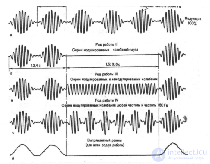
fig.4. Waveforms of the output current of the «Amplipulse-4» apparatus for various modes of operation.
The block diagram of the apparatus is shown below
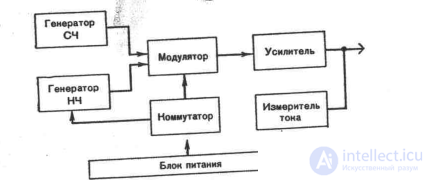
The medium-frequency generator produces sinusoidal oscillations with a frequency of 5 kHz. In the modulator, these oscillations undergo amplitude modulation by a voltage produced by the low-frequency generator. The modulated voltage is fed to the amplifier and then to the output circuit. The electronic commutator carries out 4 different modes of operation, representing an alternation of different types of current. The current meter makes it possible to monitor the RMS value of the current in the output circuit. The power supply unit provides all the units of the apparatus with the necessary voltages
The electrosleep apparatus «Elektroson-4T» is designed and manufactured by the Moscow EMA Plant.
Main technical data: maximum amplitude of pulse voltage 50 V (at a load of 5 kOhm); pulse duration 0.5 ms; pulse repetition frequency in subrange I — 5—30 Hz, in subrange II — 25—150 Hz; pulse shape close to rectangular; total duration of the leading and trailing edges not exceeding 0.1 ms; maximum value of the additional constant current component 0.5 mA (at a load of 5 kOhm); the pulse amplitude, as well as the additional constant component, are measured with a reduced error of not more than 15 A; the ripple factor in the circuit of the additional constant component does not exceed 1%; power supply from an AC mains with a frequency of 50 Hz and a voltage of 220 V ±10%; power consumed by the apparatus not exceeding 10 VA; with regard to protection against electric shock, the apparatus is built to protection class II; overall dimensions 255X180V X120 mm; weight (with a set of electrodes) not exceeding 3 kg.
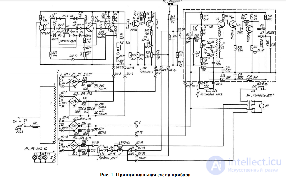
The schematic electrical diagram of the apparatus is shown in fig. II—35. The apparatus consists of three main units mounted on separate printed circuit boards: the generator and amplifier unit, the meter unit, and the power supply unit.
The pulse generator is a multivibrator built on transistors T1, T2. By means of switch B2 (the «Frequency» knob), the time-setting capacitors 1, 2—3 4 are switched, which changes the range of pulse repetition frequency control. In range I (the «Frequency» knob in position «30»), capacitors 3, 4 are switched in and the repetition frequency is adjusted within 5— 30 Hz. In range II (the «Frequency» knob in position «150»), capacitors 1, 2 are switched in and the repetition frequency is adjusted within 25— 150 Hz. Smooth adjustment of the repetition frequency within each range is provided by variable resistor 14, which changes the potential at the base of the transistors.
From the output of the multivibrator, rectangular pulses, after differentiation (the chain C5—R11, R3) are fed to the input of the limiter-shaper built on transistor T3. With the help of this stage, practically rectangular pulses with a duration of 0.5 ms are created from the negative peaks taken from the output of the differentiating chain. The rectangular pulses are amplified by a stage on transistor T4 and by the output amplifier on transistor T5.
From the collector load of the output amplifier — variable resistor 19 — the pulse voltage is fed through coupling capacitor 8 to the output jack «Patient». The shaft of resistor 19 is brought out to the control panel (the «Patient current» knob), which makes it possible to smoothly adjust the current through the patient. Zener diode D3 limits the maximum pulse amplitude to 50 V.
Resistor 27. is connected in the output current circuit. The voltage drop across this resistor, proportional to the amplitude of the current pulses, is fed to the meter unit. The meter is a peak detector, whose voltage amplitude-modulates the oscillations of the auto-oscillator. After amplification, the high-frequency oscillations are detected, and the constant component, proportional to the amplitude of the pulses in the patient circuit, is measured by a milliammeter.
The peak detector is built on diode D4 and capacitor 12. From the detector load — a divider on resistors 20, 21, 28 — the constant voltage is fed to the series-connected zener diodes D5, D6. The zener diodes are used as varicaps in the feedback circuit of the auto-oscillator built on transistor T6. The amplitude of the 100 kHz oscillations produced by the auto-oscillator is determined by the feedback voltage, which is created by the high-frequency transformer (LI—L2) and is fed, through a capacitive divider formed by zener diodes D5, D6, to the base circuit of transistor T6.
When the voltage at the output of the peak detector changes, the capacitance of zener diode D5 changes, and accordingly so does the feedback voltage of the generator. Owing to this, a close-to-linear relationship is established between the amplitude of the pulses in the patient circuit and the voltage of the high-frequency oscillations of the auto-oscillator. The high-frequency voltage is amplified by stages built on transistors T7, T8 and is detected (diodes D7, D8, capacitor 15). The load of the detector is the measuring instrument IP. With the help of variable resistor 17 the instrument is calibrated in terms of the pulse amplitude in the patient circuit (full-scale value —10 mA). Zeroing of the instrument is carried out with variable resistor 32, connected in the emitter circuit of the transistor of the high-frequency generator.
In addition to the pulse-voltage generator, the apparatus has an adjustable constant-current source for creating, in the output circuit, an additional constant component, which in a number of cases enhances the effectiveness of the pulsed current. The constant voltage is produced by means of a bridge rectifier on diodes D21—D24 with filter capacitors 22, 23. The rectifier is loaded onto variable resistor 39 (the «DPS Level» knob), from whose wiper the voltage passes through resistors 44, 41 and diode D29 to the output jack. The voltage drop across resistor 41 with button KN pressed («DPS Control») creates a current in the circuit of milliammeter IP.
The supply voltage for the transistors of the multivibrator and shaper is fed from a rectifier built on a bridge circuit with diodes D13 — D16 and filter capacitors 18, 19 and zener diodes D26, D27. The amplifier transistors are powered from a bridge rectifier with diodes D9 — D12, filter capacitor 17, zener diode D25, and the meter transistors — from a separate bridge rectifier with diodes D17 — D20 with filter capacitors 20, 21 and a zener diode
The apparatus is connected to the mains through power transformer Tr. In the mains lead a switch V1, is installed, and a fuse Pr. Indication of mains voltage is provided by incandescent lamps L1, L2, which illuminate the frequency scale on the control panel. Backlighting of the scale makes it possible to carry out the procedures in a darkened room, i.e. under conditions conducive to natural sleep.
Design of the apparatus. The apparatus (fig. II—36) is housed in a case made of impact-resistant polystyrene. On the sloped control panel are located knob 3 «30—150» of the pulse-repetition-frequency range switch, knob 2 «Frequency, Hz» for smooth adjustment of the pulse repetition frequency within the ranges, and knob 1 «Patient current» for adjusting the current in the output circuit. In the upper part of the case is instrument 5 for measuring the pulse amplitude and the additional constant current component, and knob 4 for zeroing the instrument.
In the upper right part of the apparatus there is a compartment with cover 6, containing: (see fig. II—37) knob 10 of the mains switch «Mains», knob » «Level» and button 9 «Control» for setting the value of the additional constant current component and switching the instrument for measuring it.
On the left side wall of the apparatus is the «Patient» jack for connecting the lead that joins the apparatus to the mask.
On the rear wall is an appliance inlet for connecting a detachable mains cord. The fuse holder is covered by a lid on the bottom of the case.
The apparatus with the cover removed is shown in fig. II—37. On the left side of the chassis are mounted milliammeter 6 and variable resistor 4 for zeroing the instrument. In the center are mounted transformer 7 and the meter unit in shield 5. On the right side of the chassis are panel 1 with the controls for the mains circuit and the additional constant component, printed circuit board 2 of the power supply unit, and printed circuit board 3 of the generator unit.
A special rubber mask (see fig. II—36) is used for applying the electrodes and carrying out electrosleep procedures. The mask, which is put on the patient's head, has two pairs of electrodes. One pair of electrodes is located opposite the orbits negative pole), the other —opposite the occipito-mastoid processes (positive pole).
The apparatus kit includes two masks (for adults and for children), a connecting lead, and a carrying case for the apparatus.
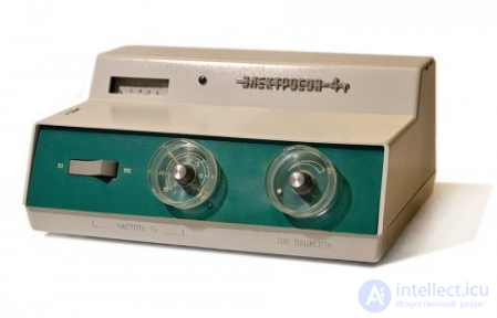
Fig. II—36. General view of the «Elektroson-4T» apparatus.
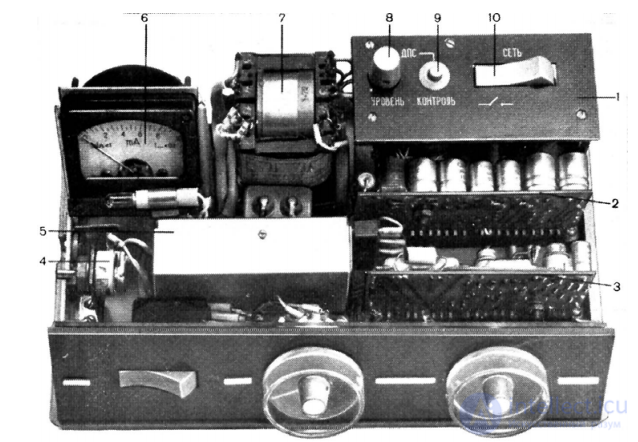
Fig. II —37. The «Elektroson-4T» apparatus with the cover removed
Operating the apparatus during procedures. Having set the «Patient current» and «Level» knobs to the extreme left position, the mains switch knob to the «Off» position, and the frequency control knobs to the specified position, the mains cord is connected to the apparatus and its plug is inserted into an outlet with a voltage of 220 V. The patient is then prepared for the procedure. The patient should be in bed in a position comfortable for sleep. Cotton wool pads moistened with saline solution are inserted into the recesses of the electrodes located in the mask, the mask is placed on the patient's head, and the plug of the electrode lead is connected to the «Patient» jack on the apparatus. The mains switch is then moved to the «Mains» position (at which the scale backlight lamps light up), and, using the zero-setting control, the instrument needle is brought to the zero mark of the scale. Pressing the «DPS Control» button, the required value of the additional constant current component is set using the «DPS Level» knob. Then, having set the specified pulse repetition frequency and smoothly turning the «Patient current» knob, the pulsed current value is increased to the threshold value, guided in doing so by the patient's sensations. At the end of the procedure, the «Patient current» and «Level» knobs are smoothly returned to the extreme left position, the mask is removed from the patient, and the apparatus is disconnected from the mains.

Comments