
Lecture
Artificial lung ventilation apparatus (ALV apparatus) — is medical equipment intended for the forced supply of a gas mixture (oxygen and compressed dried air) into the lungs in order to saturate the blood with oxygen and remove carbon dioxide from the lungs . The first model was developed in the late 1920s by physician Philip Drinker with the participation of pediatrician Charles McKhann for the treatment of poliomyelitis patients .
An ALV apparatus can be used both for invasive ventilation (via an intubation tube inserted into the patient's airway or via a tracheostomy) and for non-invasive artificial lung ventilation — via a mask.
An ALV apparatus can be either manual (Ambu bag) or mechanical. Compressed air and oxygen for the pneumatic supply of a mechanical apparatus can be fed either from the medical facility's central gas supply system or a compressed air cylinder (during transportation), or from an individual mini-compressor (a reality in the countries of the former USSR) and an oxygen concentrator. In this case the gas mixture must be warmed and humidified before being delivered to the patient.
Modern ALV apparatuses are extremely high-technology medical equipment. They provide respiratory support to the patient both by volume and by pressure.
At present, the most advanced technology for synchronizing an ALV apparatus with the patient is neurally-controlled lung ventilation technology, in which the signal traveling from the respiratory center of the medulla oblongata along the phrenic nerve to the diaphragm is captured by special high-sensitivity sensors located in the area of the transition of the esophagus into the stomach (the cardia region).
A high-frequency jet ALV apparatus can provide both high-frequency jet ALV proper and combined ventilation. In this case, pressure control is used to prevent lung barotrauma. A modern high-frequency jet ALV apparatus must have a built-in roller humidifier and a built-in gas mixture heating system to prevent severe complications of the airways. Provision for oxygen dosing and monitoring of carbon dioxide in the exhaled air is mandatory.
The simplest classification of ALV apparatuses
PPV (positive pressure ventilation), NPV (negative pressure ventilation), and generally, where does the wind blow from? In English, the words for breathing and wind sound almost the same, this is breeze and breathe. In both cases, air moves from a zone of high pressure to a zone of low pressure. Scientists who study breathing agreed to take atmospheric pressure as zero (0). If below atmospheric – negative, and if above – positive. When we breathe on our own, inhaling, we create negative pressure in the airways, and exhaling, – positive. If you didn't understand, do a few breathing exercises. The chest cavity expands, the air pressure in the airways becomes lower than atmospheric – inhalation occurs, and on exhalation – the opposite. Thus, spontaneous breathing – is NPV (negative pressure ventilation), since on inhalation the air pressure in the airways is below atmospheric. NPV ALV apparatuses exist. This is a large airtight chest with the patient's head sticking out of it. For inhalation to occur, the pressure inside the chest must drop below atmospheric, causing the chest to expand. Quite physiological, but rather cumbersome.
HFV (high frequency ventilation) – high-frequency ALV is used in nature by predators that cannot sweat, for example, dogs.
With this type of breathing, the volume of a single breath is smaller than the dead space. This type of breathing is called panting in English. Gas exchange occurs through continuous mixing of air. The lungs act as a radiator and evaporator, allowing a predator dressed in a fur coat not to die from heat shock. As the technical challenges associated with adequately humidifying and warming the breathing mixture of HFV (high-frequency ALV) apparatuses find their solutions, these remarkable machines are taking their rightful place in clinical practice.
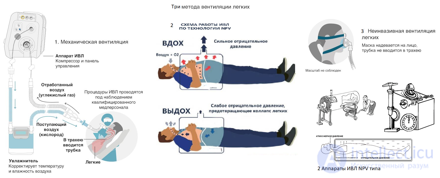
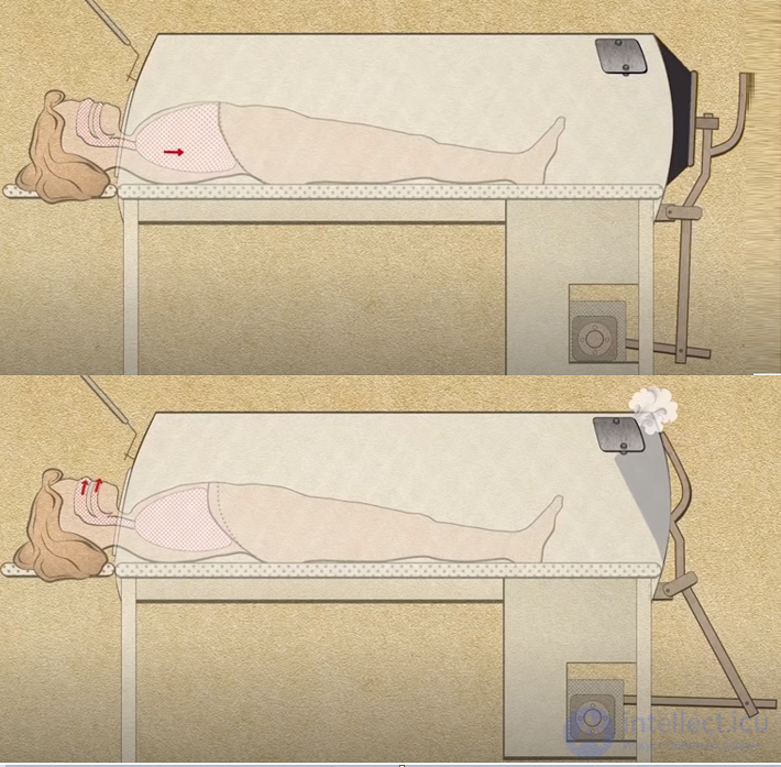
In the second half of the 19th – early 20th century, on the wave of scientific and technological progress, new methods and devices for ALV appeared. In particular, in 1907 the mobile Pulmotor respirator of the «gramophone» type was developed, which was used in mine rescue operations. However, scientists concluded that expiratory methods of ALV, based on actively blowing air into the airways, are not physiological and can lead to negative consequences: changes in lung mechanics, atrophy of the respiratory muscles, insufficient blood flow to the heart. As a result, a new type of device appeared – a negative pressure chamber, into which the patient was placed and from which air was periodically pumped out. The resulting vacuum exerted a suction effect on the chest, creating negative pressure in the airways and thereby ensuring breathing.
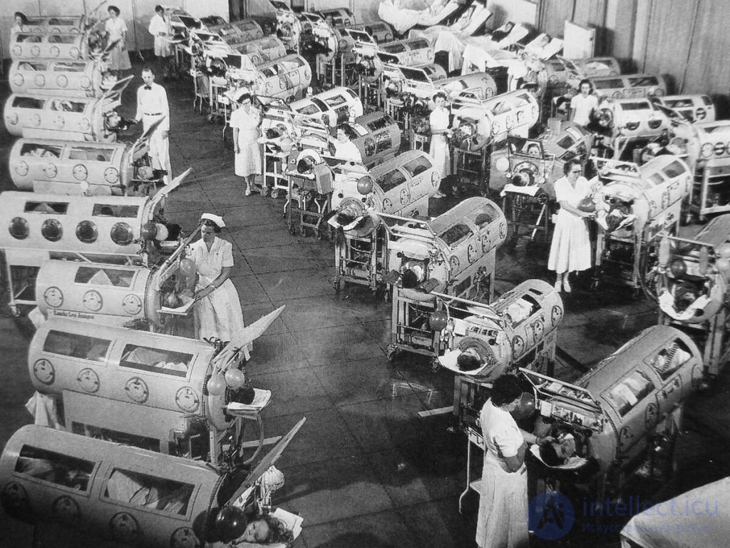
Patients affected by poliomyelitis in Engström apparatuses, 1953.
Pulmonary ventilation - is the ratio of the breathing volume on inhalation to the breathing volume on exhalation per minute. The average value of pulmonary ventilation depends on sex, age, weight and is 8 - 10 liters per minute for a person weighing 70 kg. This is the exchange of air between the atmosphere and the lungs.
1 Structural diagram of artificial lung ventilation apparatuses The diagram of any device (figure 1) contains the following main structural parts: a source of gas supplied to the patient (inspiration generator); a distribution device, determining the necessary directions of gas movement at different phases of the respiratory cycle; a mechanism for controlling the distribution device. Figure 1 – General structural diagram of ALV apparatuses
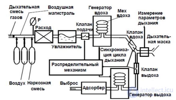
2 Main parameters and concepts in the operation of artificial lung ventilation apparatuses Today ALV apparatuses have extensive functionality and a wide range of capabilities, all of this is achieved through the development of software capabilities. Modern devices have many modes allowing precise selection of ventilation parameters to 13 avoid possible damage and provide the body with the required amount of air. Below are the main parameters, functions and capabilities of modern apparatuses. [3,4,5,6]
The method of controlling an ALV apparatus is named depending on which parameter we control (figure 2).
Volume controlled ventilation (VCV) – the control method consists in changing the tidal volume.
Flow controlled ventilation (FCV) – the control method consists in changing the flow.
Pressure controlled ventilation (PCV) – the control method consists in changing the pressure, the inspiration time.
Practical experience has led users and manufacturers of devices to the belief that it is inappropriate to separate the concepts of VCV and FCV. Volume
and flow are closely related to each other. Volume is the product of flow and time.
Since it is impossible to set breathing parameters with a single flow, in controlling «flow» the inspiration time is always set, and the volume results.
For the user's convenience, these two control options are combined into the concept of «volume-controlled inhalation» (VCV).
With VCV, the ALV apparatus, despite any obstructing and limiting changes in the respiratory system, delivers a set volume into the patient's lungs over a set time. With «volume control» there is a threat of a critical increase in pressure in the respiratory
system.
In the case of pressure-controlled ventilation (PCV), the ALV apparatus maintains the set pressure in the airways for the duration of the inspiration time and does not affect the tidal volume delivered to the patient. With PCV we risk delivering below-normal minute ventilation volume to the patient.
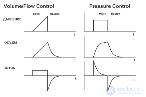
Figure 2 - Graphs of flow, pressure and volume with different methods of inhalation control, PCV and VCV
If the ALV apparatus controls pressure, the shape of the pressure curve remains unchanged. With changes in the respiratory system, the volume and flow graphs will change.
If the ALV apparatus controls volume, the shape of the volume and flow curves remains unchanged. With changes in the respiratory system, the pressure graph will change. The tidal volume is regulated either by the degree of compression of the bellows,
or by the amplitude of piston displacement, or indirectly through flow regulation.
If the ALV apparatus controls flow, the shape of the volume and flow curves remains unchanged. With changes in the respiratory system, the pressure graph will change. Flow control is carried out using devices
that regulate flow: from simple flow meters to complex electronically controlled inspiratory valves. By controlling flow, we indirectly control the tidal volume.
The main difference between PCV and VCV is that VCV immediately sets the flow characteristics (shape: rectangular or descending, and flow value), while with PCV the flow is calibrated, maintaining
constant pressure. Thus, when the parameters of the respiratory system change, the flow changes. Accordingly, the tidal volume changes.
Mechanisms for controlling the amount of gas delivered to the lungs during inhalation are usually divided into two groups. These are:
1. Volume-controlled ventilation, where the tidal volume is set directly, as in ALV apparatuses built on the basis of a breathing bellows, or as a function of inspiratory flow and time.
2. Pressure-controlled ventilation, which involves controlling the amount of gas entering the lungs during inhalation by limiting the inspiratory pressure.
Each of these methods has its own advantages and disadvantages. In modern ALV apparatuses there is a tendency to combine these mechanisms and create ventilation modes with so-called dual control, representing an attempt to combine the advantages of both ventilation control mechanisms.
The classic mode of volume-controlled ventilation is usually denoted by the English abbreviation VC or VCV (from Volume Controlled Ventilation). The structure of the respiratory cycle in volume-controlled ventilation is shown in Fig. 1. The relationship of the main ventilation parameters can be described using the following equation:
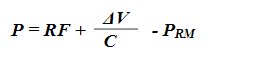
Where: P — pressure in the ventilation circuit. F — flow. AV — tidal volume. R — dynamic resistance. C — compliance.
Prm — pressure created by the effort of the patient's respiratory muscles.
The main difference of volume-controlled ventilation is that the flow characteristics during inhalation are rigidly set and do not depend on the patient's effort or respiratory mechanics indicators.
Tidal volume (Vt) — in volume-controlled ventilation is set directly. Numerically equal to the area bounded by the inspiratory flow curve (shaded region in Fig. 1). If it is possible to use PEEP, the initial value of the tidal volume is usually set at the rate of 6-8 ml per kilogram of the patient's ideal weight.
Inspiratory flow. In volume-controlled ventilation, the inspiratory flow created by the apparatus does not depend on respiratory mechanics indicators. In apparatuses built on the basis of a breathing bellows, the inspiratory flow is usually not regulated directly, but turns out to be a function of tidal volume, respiratory rate, and the ratio of inhalation to exhalation duration. With direct flow control, its peak value is set. The nature of the flow change over time can vary. Many ALV apparatuses provide the ability to choose one of several forms of inspiratory flow (constant, sinusoidal, and decelerating). In clinical practice, constant and decelerating flow forms are more often used. At an equal peak flow value, its average value, and consequently the damaging effect of stretching forces on the lung parenchyma, will be maximal with a constant flow form. In this regard, a decelerating form of inspiratory flow is preferable — when its maximum value occurs in the early phase of inhalation and gradually decreases as the patient's inspiratory demand decreases. Modern breathing apparatuses provide the ability for automatic flow control, when its magnitude and shape are calculated so as to deliver the tidal volume within the set time at the lowest possible pressure.
Peak flow is set taking into account two considerations. If the flow is too high, the tidal volume enters the most compliant areas of the lungs at high pressure, which can cause alveolar trauma. If the flow is too low, it will not be able to meet the patient's inspiratory demand, which will lead to desynchronization of their breathing with the ALV. The simplest rule — the peak flow should be approximately four times the minute ventilation volume (if the MV is 15 l/min, the patient needs a peak flow of about 60 l/min). This rule applies to a constant, i.e. rectangular, flow shape. With a decelerating shape, the peak flow is somewhat increased. A reduction in flow is required if the peak inspiratory pressure exceeds 35-40 cm H2O. An increase - with preserved spontaneous breathing, to meet the patient's inspiratory demand. In this situation, an increase in peak flow to 100 l/min or more may be required.
Inspiration duration (Ti) turns out to be a derivative of tidal volume (Vt) and inspiratory flow (F), and can be increased by means of an inspiratory pause.
Inspiratory pause (Tip) is the interval of time between the end of inhalation and the start of exhalation (opening of the expiratory valve).
In most cases, there is no need to use an inspiratory pause. It serves to differentiate peak pressure and plateau pressure when studying respiratory mechanics indicators. Usually, to achieve pressure equilibrium in the alveoli and the ventilation circuit, an inspiratory pause of at least 0.5 s is required.
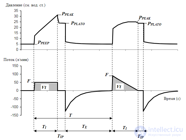
Characteristics of the respiratory cycle in volume-controlled ALV
Vt — tidal volume, corresponds to the area bounded by the curve reflecting changes in flow over time (shaded part).
F — maximum value of the inspiratory flow.
T — maximum duration of the respiratory cycle.
tip — duration of the inspiratory pause.
te — duration of exhalation.
ppeep — increased pressure at the end of exhalation (PEEP).
ppeak — peak inspiratory pressure.
pplato — plateau inspiratory pressure.
Peak inspiratory pressure (ppeak) is the maximum pressure during inhalation. In the absence of spontaneous breathing, it is a derivative of the inspiratory flow (F), tidal volume (VI), static compliance (C) and resistance (R) of the respiratory system.
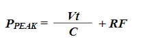
To ensure ventilation safety, the peak pressure should not exceed 35-40 cm H2O. The peak pressure during volume-controlled ALV can be reduced by lowering the peak flow, and by choosing a decelerating shape of the inspiratory flow curve, as can be seen from the data shown in Fig. 1.
Plateau pressure, or the pressure at the end of the inspiratory pause, corresponds to the alveolar pressure if the duration of the inspiratory pause is sufficient to reach equilibrium. Alveolar pressure is a derivative of the tidal volume (Vt) and the static compliance of the respiratory system (C).
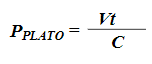
Ventilation parameters are selected so that the plateau pressure does not exceed 30 cm H2O. Otherwise, a reduction of the tidal volume is necessary. An important practical point when measuring plateau pressure is the exclusion of auto-PEEP. That is, the flow curve must reach zero by the end of exhalation.
Volume-controlled ALV can be successfully used both in patients with ventilation disorders and in patients with hypoxemic respiratory failure. The correct selection of parameters, even with partially preserved spontaneous breathing, allows ALV to be provided with minimal energy expenditure. In this case, the danger of hyperventilation and the development of pronounced respiratory alkalosis should always be taken into account. Volume-controlled ventilation does not provide for the possibility of partial respiratory support and is used only in patients not ready for transfer to spontaneous breathing.
Advantages of volume-controlled ventilation:
Disadvantages:
The ventilation mode with inspiratory pressure limitation is denoted in the English-language literature by the abbreviation (PLVoT Pressure Limited Ventilation), and occupies an intermediate position between volume ventilation and pressure-controlled ventilation. A significant drawback of volume-oriented ventilation is that guaranteeing the delivery of the set tidal volume is only possible provided the breathing circuit and the respiratory system as a whole are airtight. There is a significant group of patients in whom it is not possible to ensure this condition. These are children younger than 8 years old, in whom uncuffed endotracheal tubes are used to prevent subglottic laryngeal edema, patients with lung injury, bronchopleural fistulas, etc. Due to the lack of airtightness, the actual tidal volume always turns out to be less than the set value. The degree of leakage can change rapidly within wide limits depending on many factors - the patient's position, the amount of sputum, the effort of the respiratory muscles, respiratory mechanics indicators. Compensating for the leak requires a significant increase in the tidal volume, which is associated with the risk of hyperinflation and lung injury. Selecting ventilation parameters under these conditions becomes extremely difficult. The solution to this problem is the inspiratory pressure-limited ventilation mode. The structure of the respiratory cycle in this ventilation mode is shown in Fig. 2.
From a technical standpoint, pressure-limited ventilation on inspiration differs from classical volume ventilation by the inclusion in the breathing circuit of a valve that opens when the pressure exceeds a certain limit. This limit is called the maximum inspiratory pressure. All other settings - tidal volume, peak value and shape of the inspiratory flow, inspiratory time - are the same as in classical volume ventilation.
As long as the inspiratory pressure in the circuit has not reached the set value (Pmax), the structure of the breathing cycle is no different from ordinary volume ventilation. When the pressure in the circuit exceeds Pmax, the valve opens, and part of the inspiratory flow is vented off so that the pressure in the circuit does not exceed the Pmax value. Flow continues to be delivered into the ventilation circuit until the end of the inspiratory time Ti, which depends on the set tidal volume. Part of it reaches the airways, part is vented off. The resulting tidal volume turns out to be smaller than set. The inspiratory flow reaching the airways from the moment the maximum pressure is reached has a decelerating character.
Usually, when pressure-limited ventilation is initiated, the Pmax value is set approximately 3 cm H2O above the plateau pressure. The tidal volume is set 20% higher than the calculated value for the given patient. In case of significant leakage, the tidal volume may need to be increased to 2 liters or more.
An important point is that this ventilation mode does not guarantee delivery of the set tidal volume and minute ventilation, and continuous monitoring of the exhaled volume is required to prevent possible hypoventilation.
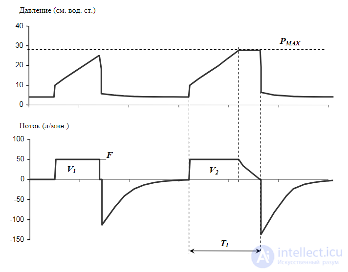
Structure of the breathing cycle during pressure-limited ventilation
Advantages of pressure-limited ventilation:
Disadvantages:
Pressure-controlled ventilation is usually denoted in English-language literature by the abbreviation PC or PCV (from Pressure Controlled Ventilation). To illustrate its principles it is convenient to use the following mechanical model. Imagine an apparatus for artificial lung ventilation built on the basis of a pneumatically driven bellows (a bellows in a flask). As long as the working pressure in the flask significantly exceeds the inspiratory pressure in the patient's airways, the amount of gas entering the lungs depends only on the final volume of the bellows, and this is a volume mode of ventilation. When a working pressure comparable to the inspiratory pressure is used, the nature of ventilation changes fundamentally (Fig. 3). Flow during inspiration is determined by the difference between the working pressure in the apparatus's flask and the pressure in the patient's airways. As the alveolar volume increases, the pressure in the airways rises, and the flow rate decreases. At the moment when pressure equilibrium is reached, the flow stops. Thus, the flow rate and the resulting tidal volume are controlled by the value of the working pressure in the flask. This pressure corresponds to the final inspiratory pressure in the patient's airways (Pi). The maximum flow rate and tidal volume are not limited. The flow always has a decelerating character and depends on the patient's inspiratory effort. The greater the pressure difference, the higher the flow rate and tidal volume.
In devices built on the basis of direct control of flow in the breathing circuit, this ventilation mode is implemented by introducing feedback. Using a system of sensors, the apparatus continuously monitors the pressure value and flow in the ventilation circuit. Through the interactive operation of the inspiratory valve servo drive, the flow changes in proportion to the difference between the set inspiratory pressure and the pressure in the ventilation circuit.
The maximum flow value is limited only by the technical capabilities of the apparatus and amounts to approximately 120-180 L/min. The greater the inspiratory effort applied by the patient, the higher the pressure gradient, and accordingly the flow and tidal volume. The pressure in the ventilation circuit is maintained for the set inspiratory time (Ti). The interval from the moment the inspiratory flow stops to the end of the inspiratory phase corresponds to the inspiratory pause (Tip). In cases where the inspiratory duration is insufficient to fully fill the lungs at the given pressure, the inspiratory flow does not reach zero. This is indicated by a break in the flow curve (marked with an arrow in Fig. 3). In the absence of circuit airtightness, in order to maintain the set pressure, the apparatus will sustain the flow throughout the entire inspiratory time. If the leak is large enough, the flow becomes constant in character. Thus, with pressure-controlled ventilation it is possible to provide artificial lung ventilation even in the presence of significant leakage. This makes pressure-controlled ventilation the method of choice in cases where it is impossible to achieve airtightness of the ventilation circuit (for example, in children and in patients with bronchial fistulas).
Ventilation is controlled using the following parameters: inspiratory pressure, inspiratory duration, respiratory rate.
Inspiratory pressure corresponds to the peak pressure, since the latter is easier to measure. Usually in adults the starting value of the inspiratory pressure is set at a level of 20 cm H2O, then adjusted so as to ensure delivery of a tidal volume calculated at 6-8 ml/kg. Starting from higher values and gradually decreasing. This approach promotes better opening of the airways and normalization of the ventilation-perfusion ratio in lung tissue. To prevent lung injury, the maximum value of inspiratory pressure should not exceed 35 cm H2O. A break in the inspiratory flow curve, as shown in Fig. 3, indicates that the maximum tidal volume at the given inspiratory pressure has not been reached. In such a case the volume can be increased by lengthening the inspiratory phase. With preserved spontaneous breathing, changing the inspiratory pressure allows the degree of respiratory support to be adjusted. As mentioned earlier, the work of breathing is the product of the tidal volume and the pressure gradient. In this situation, the degree of respiratory support, or the share of the work of delivering the tidal volume performed by the ventilator, will be proportional to the ratio of the set inspiratory pressure to the pressure generated by the patient's respiratory muscles. Under normal respiratory mechanics parameters, a 100% level of respiratory support corresponds to an inspiratory pressure of approximately 15 cm H2O.
Inspiratory duration in PCV mode is set directly. As a starting value in an adult it is set at approximately 1 second. It depends on the size of the lungs. Approximate values of the starting inspiratory duration and inspiratory pressure depending on the patient's ideal weight are presented in Table 2.
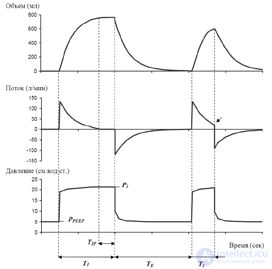
Structure of the breathing cycle during pressure-controlled ventilation
Pi — inspiratory pressure.
PEEP — elevated pressure at the end of expiration (PEEP).
Te — expiratory duration.
Tip — duration of the inspiratory pause.
In modern ventilators these values are stored in memory and set automatically when the patient's weight is entered. In PCV mode it is possible to choose between direct control of the inspiratory duration or changing it together with the respiratory rate while keeping the ratio of inspiratory to expiratory duration constant. The first mechanism allows minute ventilation to be adjusted while keeping the tidal volume characteristics unchanged. The second - to change the respiratory rate while keeping the mean airway pressure unchanged. Some devices allow the duration of the breathing cycle to be changed while keeping the expiratory duration constant, which may be necessary to prevent auto-PEEP.
Tidal volume is not set directly, but turns out to be a derivative of the inspiratory pressure, the inspiratory duration, respiratory mechanics parameters and the patient's respiratory effort. With a sharp increase in airway resistance, reaching the set inspiratory pressure does not guarantee delivery of the required volume. This can be a cause of hypoventilation and threatening hypoxia in cases of sputum accumulation, bronchospasm, or desynchronization with the patient's breathing. A necessary condition for the safety of pressure-controlled ventilation is continuous monitoring of tidal volume.
Inspiratory flow. Pressure-controlled ventilation mode does not provide for direct regulation of the inspiratory flow. Its maximum value is limited only by the design capabilities of the apparatus. Such a situation is not advantageous in all cases. If lung compliance is low, the tidal volume is delivered over too short a time. Most of the inspiration is taken up by the inspiratory pause, which does not always have a favorable effect on the conditions of tidal volume distribution, especially in cases with a heterogeneous nature of lung damage.
Table 2
|
Selection of ventilation parameters in patients without significant impairment of lung mechanics depending on ideal body weight
|
|||
|
Ideal body weight (kg)
|
Inspiratory pressure
|
Inspiratory duration
|
Respiratory rate
|
|
in children |
|||
|
2-5 |
15 |
0.6 |
35 |
|
6-8 |
15 |
0,6 |
25 |
|
9-11 |
15 |
0,6 |
20 |
|
12-20 |
15 |
1,0 |
20 |
|
21-26 |
15 |
1,0 |
15 |
|
27-29 |
15 |
1,5 |
15 |
|
in adults |
|||
|
30-39 |
15 |
1,0 |
14 |
|
40-59 |
15 |
1,0 |
12 |
|
60-89 |
15
|
1,0
|
10 |
|
90-100 |
18 |
1,5 |
10 |
|
above 100 |
20 |
1,5 |
10 |
Control of inspiratory flow parameters via the slope of the pressure curve
Pi — inspiratory pressure.
Ti — inspiratory time.
Tr — rise time of the inspiratory pressure.
To ensure optimal ventilation conditions, modern ventilators in pressure-controlled ventilation mode provide the possibility of indirect control of the inspiratory flow. This is achieved by changing the rate of rise of the inspiratory pressure (Fig. 4). The set pressure (Pi) is not reached immediately, but over a certain time (Tr), which can be expressed either directly in seconds, or as a percentage of the inspiratory duration (Ti).
A slowed rise of inspiratory pressure is used in pronounced disorders of lung mechanics with heterogeneous lung damage, in cases of absent spontaneous breathing. The tidal volume is then delivered at a lower starting flow value, over a longer time. This promotes better distribution of the tidal volume, and ventilation of less compliant areas of the lungs.
Reaching the set inspiratory pressure at the start of inspiration corresponds to a rectangular shape of the pressure curve, when the starting flow value is maximal, the tidal volume is delivered in a short time, and the flow decelerates quickly. A rectangular shape of the pressure curve is preferable with a high inspiratory demand, bronchospastic conditions with a pronounced increase in the time constant of the respiratory system, when, to prevent auto-PEEP, it is necessary to quickly deliver the tidal volume and ensure a sufficient duration of expiration.
If the starting flow is too high, due to the inertia of the apparatus's systems, a peak exceeding the set inspiratory pressure value (Pi) can be detected at the initial section of the pressure curve.
Advantages of pressure-controlled ventilation:
Disadvantages:
Changeover of the phases of the breathing cycle
The mechanisms by which the changeover of the phases of the breathing cycle is carried out determine the difference between mandatory and assisted ventilation. Early models of ventilators had no capability for synchronization with the patient's spontaneous breathing. Artificial lung ventilation under such conditions required deep sedation and even muscle relaxation until the pathological process resolved. Transferring the patient to spontaneous breathing before their respiratory muscles atrophied was a serious problem. This made it necessary to solve a whole series of technical problems in order to enable interaction between the patient and the ventilator at the level at which one can speak of assisted lung ventilation and titrated respiratory support.
Mandatory ventilation
With mandatory ventilation, the changeover of the phases of the breathing cycle is carried out by time, in accordance with the set respiratory rate. The inspiratory duration, depending on the mode selected, can be set directly, determined as the ratio of inspiratory to expiratory duration (I:E), or be a function of the tidal volume and inspiratory flow. The respiratory rate is chosen so as to ensure minute ventilation at the level necessary to eliminate carbon dioxide and maintain blood pH within acceptable values (7.3-7.4). Mandatory ventilation is used in cases where spontaneous breathing is absent or suppressed. Under such conditions, preference is most often given to volume ventilation, since it guarantees delivery of the set tidal volume and allows direct measurement of respiratory mechanics parameters. The volume-controlled mandatory ventilation mode is usually denoted as CMV (from Continuous Mandatory Ventilation). Pressure-controlled mandatory ventilation is used in patients with significant impairment of respiratory mechanics, when it is not possible to ensure delivery of the required tidal volume within the permissible pressure range.
As spontaneous breathing recovers, the problem arises of ensuring synchronous operation of the apparatus with the patient's own breathing rhythm. The first step in solving it is synchronized mandatory ventilation.
The synchronized volume-controlled mandatory ventilation mode is most often called Assist Control (A/C) in English-language literature; translated literally into Russian this sounds like assisted mandatory ventilation. The analogous pressure-controlled mode is usually denoted by the general abbreviation PCV (Pressure Controlled Ventilation).
Synchronization of mandatory breaths with the patient's spontaneous inspiratory attempts is achieved by means of an inspiratory trigger. The possible mechanisms of its operation and their characteristics are listed in Table 3. In clinical practice, systems responding to a drop in pressure or flow in the ventilation circuit have become the most widespread. The apparatus's response time to a patient's inspiratory attempt does not differ significantly between the two cases. A pressure detector is technically simpler. Its disadvantages are:
Response to extraneous pressure fluctuations, which can lead to false triggering up to auto-cycling,
A sharp decrease in sensitivity in the presence of a leak, which makes it difficult to use a pressure detector as an inspiratory trigger in the absence of ventilation circuit airtightness.
Choosing the sensitivity level requires taking the following factors into account. Too high a sensitivity can be a cause of hyperventilation due to reaction to artifacts. With too low a sensitivity, the energy cost of breathing increases and desynchronization is possible. Usually at the start of artificial lung ventilation the trigger sensitivity is set at the level of -2 cm H2O, then adjusted individually so as to ensure optimal ventilation conditions.
A flow trigger makes it possible to avoid the above-listed problems to a certain extent. It is significantly more resistant to auto-cycling, and retains sensitivity in the absence of ventilation circuit airtightness and with a leak of up to 30 L/min or more. A flow trigger requires setting a base flow. Its value must be no less than the sum of the leak flow and the trigger threshold. Thus, if the leak flow is 6 L/min, and the trigger sensitivity is 0.5 L/min, the base flow is set at a level of no less than 6.5 L/min. In addition, the presence of a base flow makes it possible to reduce the resistance of the ventilation circuit at the moment of inspiration initiation, which helps reduce the energy cost of breathing.
A flow trigger is significantly more complex technically, since it requires differentiating the leak flow from the flow created by the patient's inspiratory effort. A solution to this problem is registering flow at several points, in the inspiratory and expiratory parts of the ventilation circuit. This increases the complexity and cost of the system. Another option is placing the flow sensor beyond the Y-piece, between the circuit and the endotracheal tube connector. Such a solution allows the most accurate differentiation of the flow in the circuit and the flow entering the patient's airways, but is associated with the problem of sensor contamination by sputum and condensate.
The inspiratory trigger is the only "interactive" element in synchronized volume-controlled mandatory ventilation. With sufficient sensitivity, in response to an inspiratory attempt the patient receives a synchronized mandatory breath. If inspiratory attempts are absent, or the trigger sensitivity is too low, inspiration is initiated by time in accordance with the set respiratory rate. In synchronized mandatory ventilation mode, in the absence of spontaneous breathing or with the trigger sensitivity set to zero, the resulting respiratory rate will equal the set rate. If the trigger is activated, the respiratory rate will increase in accordance with the frequency of the patient's inspiratory attempts. The starting respiratory rate level in adults is set within the range of 12-16 per minute, calculated from a minute ventilation volume of 100 ml/kg. Subsequently the respiratory rate is adjusted based on analysis of acid-base status and blood gas indicators. With hypoventilation and respiratory acidosis, the respiratory rate is increased. In case of hyperventilation, deepening of sedation is required. Provided the peak flow value is adequate, synchronized volume-controlled mandatory ventilation mode allows full respiratory support to be provided, with the exception of the work of activating the apparatus's trigger. Pressure-controlled ventilation has a number of advantages in such a situation, since it allows synchronization of the inspiratory flow with the patient's respiratory efforts to be achieved, and makes it possible to adjust the degree of respiratory support. Therefore, as spontaneous breathing recovers, most clinicians give preference to the PCV mode.
Table 3 Characteristics of inspiratory attempt detection systems
|
Signal
|
Sensor Response time
|
Properties
|
|
Abdominal wall movements
|
Acceleration detector 53 + 13 ms
|
Reliability depends on correct positioning Difficult to use with paradoxical chest or abdominal wall movement Fixed sensitivity value
|
|
Thoracic impedance
|
Chest electrodes 70-200 ms
|
Reliability depends on electrode position Contact reliability (gel drying out) Long delay
|
|
Circuit pressure
|
Pressure detector 40-100 ms
|
Easy to use Auto-triggering, high energy cost of breathing Measurement accuracy depends on circuit compliance No tidal volume control
|
|
Flow
|
Differential pressure detector 25-50 ms pneumotachometer
|
Ease of use Tidal volume and leak control Auto-triggering, sensitivity to moisture and contamination
|
Impedance pneumograph for research applications
The block diagram of an impedance pneumograph using an 8080A microprocessor [104] is shown in Fig. 5.17. The device uses a current generator and allows selection of a two-, three-, or four-electrode recording scheme. Using a microcomputer makes it possible to set the magnitude, frequency, and safe voltage on the electrodes. The instrument measures the magnitude and phase shift of the detected signal relative to the reference signal. The strength and frequency of the supply current can be varied within 0.02-1 mA and 1—99 kHz, respectively. After amplification via an AM demodulator, the magnitude of the amplitude-modulated signal, proportional to the measured impedance, is determined. The phase shift is determined by feeding fast clock pulses through a counter over a period equal to the time difference between the zero-level crossings of the reference and detected signals. The resulting value is a linear function of the phase difference between the two signals.
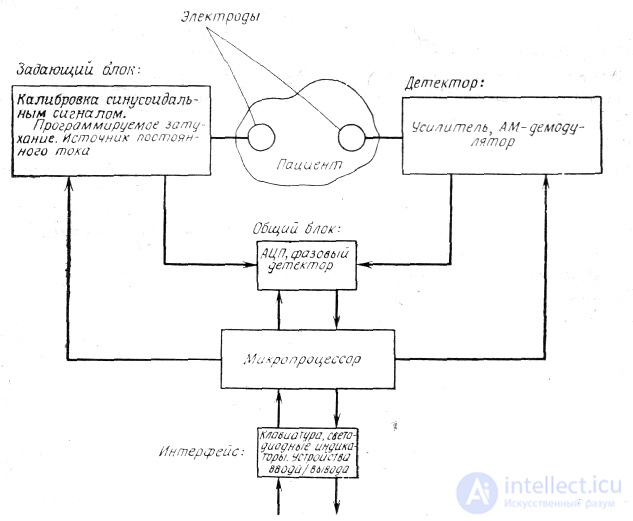
Fig. 5.17. Block diagram of an impedance pneumograph
The analog-to-digital converter provides the interface between the demodulator and the microprocessor. The operator sets which of the supply circuit parameters are to be displayed and which digital information is to be transmitted to the external input/output device. The microprocessor performs control functions as well as communication with external devices.
The microprocessor is a board measuring 3.5 x 4.5 inches (1 inch = 25.4 mm), having 512 bytes of UV-erasable programmable ROM, 128 bytes of RAM, separate 8-bit input/output ports, and all the necessary clocking and decode-control circuitry.
+Using a microprocessor provides versatility in solving various tasks and the ability to program repeat studies with good reproducibility. This is especially important when using methods based on impedance measurement, where electrode placement may change or different subjects are being studied. Developing the software for this device, writing the programs in machine code, took 2 man-months, and the cost of the hardware was about $2000.
The portable MEDDARS data acquisition and analysis system uses a General Instrument's CP-1600 microcomputer [62]. The clinical-diagnostic capabilities of this system allow laboratory studies of the respiratory system and cardiac catheterization. Controlled modules can be used to record biopotentials, pressure, and temperature readings. The microcomputer provides a non-fading display of alphanumeric characters, cursors, a scale grid, and the signal trace. It automatically checks each controlled module, stores logs, manages input/output, and performs a self-test of all important functions.
In [53], an Intel 8080 microprocessor with programmable ROM and RAM of 8 Kbytes each was used to assess lung function. The system receives information over four analog input channels, processes it, and subsequently displays it on screen as X—Y graphs or outputs it as a hard copy printout. Using an ordinary cassette tape, the processor's RAM is loaded with programs written in assembler or BASIC. The programmable ROM contains a system monitor and standard programs for reading and displaying data on the screen. The cursor control program makes it possible to select exactly those groups of data that are needed for processing. The system can process the results of standard lung function tests and measure airway aerodynamic resistance and lung compliance.
To facilitate the study of lung function, a conventional spirometer is coupled to a microprocessor [16]. Such a system is equipped with indicators to make it easier to enter the patient data, time of day, and ambient temperature from the keyboard. Based on the results of a forced inspiration and the maximum possible lung ventilation for the patient, the microcomputer calculates and prints out, with a temperature correction, 13 parameters.
For rapid field testing of lung function, a MOS Technology 6502 microcomputer on a KDM-1 board is used. A potentiometer installed in a water-filled spirometer generates electrical signals that are fed to the microcomputer. The microcomputer requests the necessary constants from the operator, stores the lung volume data, calculates and displays the following values: vital capacity, forced expiratory volume, mean forced expiratory flow, and peak expiratory flow.
Lung function data is processed using two Intel 8080 microprocessors [89]. The patient is asked to exhale as forcefully as possible into the spirometer bellows and then inhale that air back. The two 8080 microprocessors form a system for determining air volumetric flow in real time and, in addition, perform an abbreviated statistical analysis of the data. Based on the data obtained, the physician can draw a conclusion about the condition of the patient's lungs and establish the severity of a disease such as asthma.
One of the microprocessors handles the data input programs and their analysis, while the other performs the process-control functions necessary for normal operation and generates the graphical display in real time. The system uses 4 Kbytes of static,
•8 Kbytes of dynamic RAM and 12 Kbytes of erasable programmable ROM.
To measure lung tissue compliance, a 6502 microprocessor with 4 Kbytes of memory is used. A portion of air is introduced into the patient's airways over 250 ms
•at a rate of 400 ml/s. In doing so, the pressure and the airflow value in the airways are measured. Since lung compliance is inversely proportional to the pressure rise and directly proportional to the flow value, the microcomputer calculates the degree of lung tissue compliance from the data of a single air portion input over one breathing cycle.
To process data obtained using a body plethysmograph (a chamber in which the person is placed), an 8080 microcomputer is used [33]. The operator selects the examination procedure by pressing keys. The necessary program is then loaded and executed. After calibration, the operator is notified of obtaining such parameters as the magnitude and pressure of the airflow the patient is breathing, as well as the airflow entering and leaving the chamber. The programs are used to compensate for amplitude and phase signal distortion and to display the results in graphical or digital form.
For diagnosing, investigating the causes of, and preventing pulmonary edema in dogs, a MOS Technology 6502 microprocessor on a KM-1 board is used [122]. Using pressure and airflow rate sensors, the microcomputer records inspiration. Tidal volume is calculated by summing the signals arriving from the sensors at a frequency of 180 Hz. By multiplying each flow rate value by the pressure value and summing the resulting products, the total work of breathing is determined. In addition, the degree of lung compliance and the work expended on lung distension are determined.
Changes in the values of these parameters can reveal symptoms of a possible increase in the amount of interstitial fluid.
A simplified circuit for monitoring lung ventilation [60] is shown in Fig. 5.18. The input analog signals of this system are the values of tidal volume, flow rate, and pressure. In addition, a fourth logic signal is supplied, indicating to the microprocessor which phase — inspiration or expiration — the artificial respiration apparatus is in.
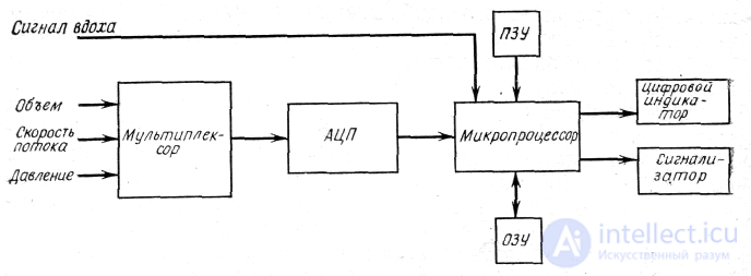
Fig. 5.18. Block diagram of a monitoring system for artificial lung ventilation.
The system uses a 4-bit central processor (Intel 4004), 80 words of RAM, and 512 words of ROM for storing various signal processing and display subroutines. The subroutines are used for:
The microprocessor provides broad system capabilities while reducing the amount of hardware. In addition, the system provides for further development, since its functions can be expanded by introducing new programs.
Automatic monitor for studying respiration in rodentst . To study the effect of cigarette smoke on the respiratory organs of rats, a microprocessor system was developed for recording and retrieving data on inspiratory capacity (IC), tidal volume (vt) and the respiration rate of rats before, during, and after exposure to cigarette smoke (Fig. 5.19). The values VV
and V are determined by integrating the respiration rate (V),
obtained using a pneumotachometer. The values of V and V are continuously recorded on a chart recorder. The system also detects small changes in vt and V, making it possible to quantitatively assess the effect on rats of smoke from experimental cigarettes of various brands. The calculation of tidal volume and respiratory period values and their display on the cathode-ray tube screen is performed by the microprocessor.
The output signals from the zero-crossing detector allow the volume integrator to be reset to its initial state at the end of each expiration. These same signals are used as the zero level for measuring vt- The zero-crossing detector sends a start-of-count signal to the computer for building histograms and triggers the respiration-rate counter to determine the number of breathing movements during the recording time.
+The computer's histogram-building operation is controlled by an Intel 8008-1 processor (ProLog model 8111). The trigger signal initiates analog-to-digital conversion of the data coming from the volume integrator. The final digital value of vt is entered into a memory array, where the tidal volume data needed for building the histograms are stored. The time intervals between two successive trigger signals are stored as a histogram of respiratory periods. Both histograms are displayed simultaneously on the screen of a Tektronix 603 CRT monitor. For the value of vt the histogram bin size can vary within 0.01—0.08 ml and have a maximum resolution of 256 bins at their smallest size. The bin size of the respiratory-period histogram varies within 0.01—0.08 s. The largest bin values for the first and second cases are 2.56 ml and 2.56 s, respectively. To build the histograms, the computer calculates average tidal volume values (its value over several breathing acts). The limiting error in volume recording is ±5% of its actual values, and in respiratory period recording it is less than 1%.
Let us demonstrate, using the example of an anesthesia system (Fig. 5.20) developed at Massachusetts General Hospital, how incorporating a microcomputer into an inhalation anesthetic delivery apparatus can expand the latter's capabilities*.
To control the gas flows and anesthetic concentration, the system uses a digital on-off switching principle, whereby the characteristics of the breathing circuit essentially remain unchanged. System reliability is increased due to the reduction in the number of removable units. The microprocessor also makes the system easy to modify.
The needle valves and rotameters of conventional anesthesia equipment are replaced in the system by digital valves. Each valve has eight orifices, which open and close on command from the microcomputer. The gas flow passing through the orifices is calibrated using sonic nozzles located in each of the orifices. The flow value is a function of the upstream pressure, the cross-sectional area of the orifices, and the temperature.
The gas flows passing through the orifices are divided in a 1:2 ratio. In other words, through each successive, larger-diameter orifice passes a gas flow twice that of the previous one at the same upstream pressure. After the desired gas flow rate is set on the display and control panel, the microcomputer measures the upstream pressure (using a pressure sensor) and opens the corresponding orifice; the two gases mix, forming a combined flow.
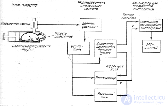
Fig. 5.02 Block diagram of a system for monitoring breathing in rats, consisting of three subsystems: a plethysmographic tube, an analog signal and display shaper, and a computer display for building histograms [25].
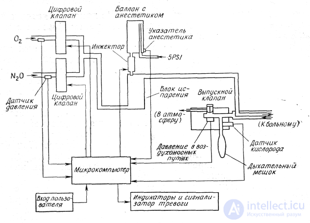
Fig. 5.20. Anesthetic delivery system.
The vaporizers used in conventional anesthesia machines are replaced by a digital injection system, similar to the fuel injection system used in some types of automobiles. To set the liquid parameters, the code printed on the anesthetic canister is first entered into the microcomputer, and then the desired anesthetic concentration in the total gas flow is set. The actual volume of anesthetic is determined using a thermistor placed in the injected stream. To fully vaporize the anesthetic after it is atomized by the injector nozzle, a copper coil is used. This eliminates the need for temperature compensation, since the vaporization process is not accompanied by a drop in the temperature of the remaining portion of the liquid anesthetic.
Control of the system under consideration is performed using an Intel 8080 microprocessor, which at the time of its development was the only device meeting the requirements imposed on the hardware and software [116]. Control includes operations such as reading signals from the sensors, calculating control actions based on operator commands and sensor signals, and controlling the effectors (control elements), while the communication functions consist of interpreting user commands received from the control panel, displaying the current control parameters and measured values, and issuing an alarm signal in the event of threatening conditions or conditions not corresponding to the set parameters.
The current monitoring readings and the values read from the sensors for airway pressure and oxygen concentration
The hardware of the anesthesia delivery system is built around an Intel 8080 microprocessor. The software was developed on the basis of the MIT MULTICS computing system in PL/M (a high-level language created for microcomputers by Intel). The total development cost was $150,000. The cost of manufacturing the next unit of the system is $15,000. In series production, the cost of the system will drop to a level comparable to that of conventional anesthesia equipment.
A compact anesthesia monitor and its control device were created by the authors of the work. Every 20 s, data is read from 32 channels coming from conventional physiological monitors and converted into digital form with an accuracy provided by 12 bits. The monitor is used to monitor the parameters of the respiratory system (oxygen concentration, carbon dioxide, halothane, gas flow, pressure, and the operating characteristics of the artificial respiration apparatus) and circulatory indices (ECG, arterial and venous pressure, internal and skin tempera
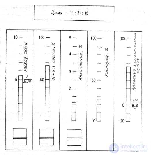
Fig. 5.21. Front panel of the anesthesia delivery system [116].
(Note the similarity of the gas-discharge indicators to conventional rotameters.)
ture, frontomastoidal plethysmogram). The monitor performs preliminary data processing, which includes determining the maximum and minimum of the inhaled gas flow, pressure, and gas concentration. The mean pressure is calculated from the central venous pressure values. In addition, based on data obtained from two or more input channels, corresponding parameters are calculated; for example, from the gas flow rate and pressure, the values of
-airway resistance and the work expended in overcoming it are determined.
In the event of unforeseen changes in the incoming signals, the monitor automatically detects the error and its type. Errors may be caused by the condition of the equipment (for example, sensor failure) or by a change in the patient's condition.
The microprocessor uses a 16-bit large-scale integration circuit (LSI-11). This type of microprocessor was chosen because it could be used together with a PDP-11 computer, which allowed editing and assembling. The presence of 8000 words of magnetic memory made it possible to build a more compact unit than would have been possible using a floppy disk. The use of a keyboard operating in the American Standard Code for Information Interchange (ASCII) provides for entering commands to perform calibration, after which the system notifies the user of all stages of the procedure.
The display provides feedback in cases requiring user intervention, and also outputs error messages. The custom-built display screen shows 16 three-digit numbers, updated every second. When the program detects an error, flashing lights are activated. A specially designed modem with a throughput of 1200 baud transmits the data collected over 4 hours for subsequent recording on cassette tape.
This system makes it possible to display all the information the anesthesiologist needs on the screen of a single digital display, provides a large volume of information, and facilitates calibration
•of the system, causes a light signal to appear on the display when there are sudden changes in parameters, and automatically records the data in memory.
The flexibility of the computer makes it easy to expand the monitoring system. For example, the design team is currently developing a model that can be used to predict the patient's most probable future condition and signal significant deviations from that condition.
To collect, format, and display physiological parameters, a Z80 microprocessor was used in [99]. Previously, anesthesiologists observed and recorded data every 5 min, or whenever the need arose. With the new system, the readings are automatically displayed on a TV screen. This allows the anesthesiologist to monitor their deviations and reconstruct past events.
The system receives the following data coming from the monitors: arterial pressure readings, heart rate, venous pressure, intracranial pressure, nasopharyngeal temperature, and end-tidal carbon dioxide concentration.
The Z80 microprocessor used in the system has 26 Kbytes of RAM and external memory on standard cassette tapes (Fig. 5.22). Data entered in a specific format is placed in an 8 Kbyte RAM, which is used to build the graphical image on the television monitor screen. Using a special controller, the Z80 microprocessor displays alphanumeric information on the same display. The cost of the hardware is $2500.
Clinical use of this system revealed the following advantages: the ability to detect events that would have gone completely unrecorded with traditional devices; for example, detection of brief pressure drops, the ability to store data obtained during an acute situation (when the anesthesiologist is fully occupied with emergency measures), and the ability to record responses to trial doses of hypotensive drugs so that the physician can determine their required therapeutic dose.
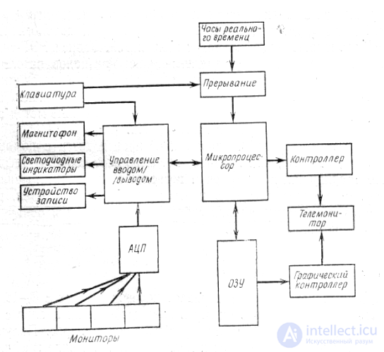
Fig. 5.22. Block diagram of the hardware of a system for monitoring the physiological parameters of a patient during surgery
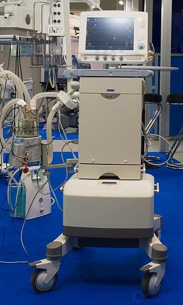
MAQUET SERVO artificial lung ventilation (ALV) apparatus
Classification of ALV apparatus
"Bird VIP" ventilator for newborns
"Oriental Radcliffe" model of an artificial respiration apparatus, mid-20th century
The classification of artificial lung ventilation apparatus is carried out in accordance with GOST 18856-81.
Division of ALV apparatus by the breadth of functional capabilities and patient age
Division of ALV apparatus by drive and control
Special-purpose ALV apparatus:
In patients who underwent artificial lung ventilation (ALV) for more than 96 hours, factors determining mortality and quality of life. Materials and methods. The study included patients who underwent long-term ALV. Mortality and quality of life were assessed in the patients. Results. Only 23 (65.7 %) of 35 patients were alive at the end of the first year after long-term ALV. The age of patients in the survivor and non-survivor groups was 45.3 ± 15.9 and 64.0 ± 13.5 years, respectively (p < 0.001). Mortality was significantly affected by patient age, the absence or presence of 4 or more comorbidities, severity of condition (assessed using the APACHE III scale), quality-of-life score on the IADLs scale (before hospitalization), and the presence of pressure ulcers that developed during treatment. One year after discharge from the hospital, 43.5 % of patients remained physically limited and required ongoing care. Survival after long-term ALV was 52.2 % (over 20 months). Conclusion. Thus, more than one-third of patients die within 1 year after long-term ALV, and about 70 % of survivors have functional impairments and require ongoing or partial care.

Comments