
Lecture
LITHOTRIPSY
Kidney stones can cause the patient enormous discomfort while they are passing through the urinary tract. Ultimately, these stones can lead to loss of function of the affected kidney. Surgery (dichotomy), may be used to remove stones, but this procedure carries all the risks, complications, discomfort and loss of working capacity inherent in most surgical interventions. In contrast, lithotripsy (stone crushing) is among the surgical procedures performed non-invasively, or with minimal invasive surgical intervention, and therefore it does not carry such risks and complications. This procedure consists of crushing the stone in vivo in such a way that it passes out through the urinary tract as small particles, the passage of which is not accompanied by serious discomfort and loss of working capacity (Bush, Branneb, 1988).
In percutaneous lithotripsy, a probe is inserted through a small incision to the site where the kidney stone is located, with the probe insertion process monitored by means of X-ray fluoroscopy. The crushing process itself is carried out either by means of a mechanical shock wave produced by a controlled electric discharge at the tip of the probe, or by means of an ultrasonic-wave-generating transducer mounted in the probe. The crushed stones are removed from the kidney in pieces using a special device on the probe. Some of them pass out on their own through the urinary tract.
Extracorporeal shock-wave lithotripsy is a fully non-invasive procedure that can be used to remove kidney stones. Fig. 15 shows the main structural elements of the devices used to perform such operations. A series of mechanical shock waves is generated at the focus of an elliptical reflector so that they concentrate at the conjugate focus a few centimeters from the reflector. Both the reflector and the patient are immersed in desalinated degassed water so that the patient can be moved until the stone falls into the point of concentration of the shock waves. Correct positioning of the patient is very important, so a two-coordinate X-ray apparatus is used for positioning, which also serves to track the process of stone destruction. A high-voltage pulse (about 20 kV) is applied to the spark gap, in which the discharge produces a shock wave. This wave propagates through the water to the conjugate focus. The patient is placed on a special movable platform, which makes it possible to change his position with high precision, while the operator monitors the location of the stone on the monitor of the two-coordinate X-ray apparatus. When the patient is in the required position, shock waves are generated in the spark gap by repeated discharge. Destroying a kidney stone 1—2 mm in diameter into small fragments that can pass painlessly through the urinary tract may require up to 2000 discharges.
After such treatment, most patients can return to normal life within 2 days. This is significantly less than is required for recovery after surgery to remove a stone. Therefore, although such a device is expensive and complex to operate, its advantages are obvious both from the standpoint of patients and from the standpoint of the effectiveness of medical institutions.
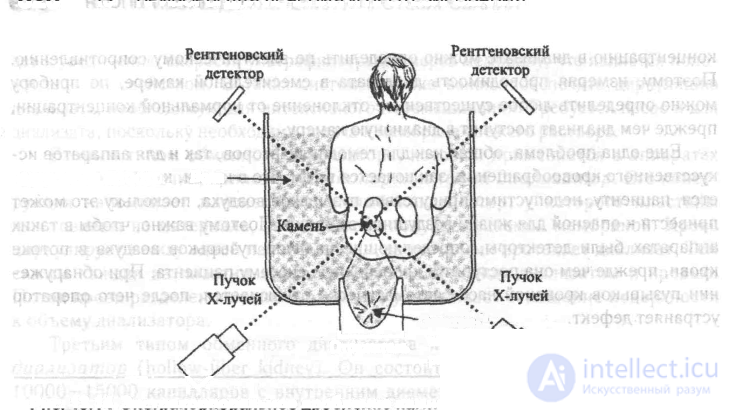
Fig. 15 Extracorporeal shock-wave lithotripsy.
A two-coordinate X-ray apparatus (X-rays) is used to make sure that the stone is at the focus of the elliptical reflector of the shock-wave generator.
Electronic "scalpel".
+The ESU-500-4 (ES-500M) electrosurgical unit is intended for cutting soft tissue, coagulating blood vessels and cutting soft tissue with simultaneous coagulation of small blood vessels by high-frequency current when performing surgical interventions in in-patient conditions.
The main technical characteristics of the ESU-500-4 unit are given in Table 1.
Table 1.
|
Name of characteristic |
Numeric values |
|
1. Operating mode of the device: cutting, coagulation, mixed |
|
|
2. Maximum power at optimal load in modes, W: cutting coagulation mixed |
420 130 200 |
|
3. Minimum power at optimal load in modes, not more than, W: cutting coagulation and mixed |
10 15 |
|
4. Optimal load, Ohm
|
300 |
|
5. Load range, Ohm
|
50-5000 |
|
6. Fundamental frequency, kHz |
1760±44 |
|
7. Radio pulse repetition frequency in modes, kHz coagulation mixed |
22±2 66±9 |
|
8. Duty cycle of radio pulses in modes: coagulation mixed |
3-0,5 2±0,4 |
|
9. Depth of amplitude modulation, % |
80-100 |
|
10. Number of output power adjustment steps |
23 |
Continuation of Table 1.
|
Name of characteristics |
Numeric values |
|
11. The device automatically switches off the HF current in case of a fault in the grounding circuit or the passive electrode |
|
|
12. Supply voltage of the device, V
|
220±10 |
|
13. Mains supply frequency, Hz
|
50±0,5 |
|
14. Power consumed by the device, not more than, kVA |
1,8 |
|
15. Time for the device to be ready for operation after being switched on, not more than, s |
30 |
|
16. Operating mode intermittent (repeated short-term): HF current on-time, not more than, min pause time, min |
2 2 |
|
17. Time the device may remain continuously connected to the mains supply, not more than, h |
8 |
|
18. Overall dimensions of the HF source unit, mm
19. Weight of the HF source unit, kg |
524x190x505
32 |
|
20. Method of sterilization of the electrodes – any known method
|
|
|
21. Method of sterilization of the electrode holder with cable – dry-heat method. In a hot-air oven with air temperature not more than, °C |
132 |
|
22. Sterilization time of the electrode holder with cable, not less than, h |
2 |
Content of precious metals:
gold-1,6841
silver-5,1626
Note: The indicated precious materials are contained in purchased electroradio components (ERC).
3.1. The complete set of the ESU-500-4 electrosurgical unit is given in Table 2.
Table 2.
|
Name |
Designation |
Qty |
|
1. HF source unit |
MB2.068.022 |
1 |
|
2. Foot switch |
MB4.255.005 |
1
|
|
3. Case with instruments in it: 1. Electrode holder 2. Cable 3. Passive electrode 4. Box with instruments in it: a) straight knife electrode b) curved knife electrode c) straight loop electrode d) curved loop electrode e) loop electrode Ø = 10 mm f) cup electrode Ø = 10 mm g) curved cup electrode h) ball electrode Ø=50 mm i) ball electrode Ø=3 mm |
MB6.876.173 MB5.139.030 TGS.644.049 09.130.00.00
MB8.865.064 AI 5013.110.00
AI 5013.111.00
AI 5013.112.00
AI 5013.113.00
AI 5013.114.00
AI 5013.115.00
AI 5013.116.00
AI 5013.117.00
AI 5013.118.00 |
1 2 1 1
1 2
2
1
2
1
1
1
1
1 |
|
5. Spare parts kit case containing: 1) electrode holder 2) incandescent lamp
3) fuse
4) fuse
5) data sheet 6) pair for the ESU-500-4 (ES-500M) unit |
MB6.873.030 MB5.139.030 SG-24-1,2 TU 16-535.259-75 VP1-1-5a OYu.480.003 TU VPZT-3-10a OYu.481.012. TU MB2.068.023 PS
|
1 2
8
10
1 1
1
|
4.1. The device is a high-frequency current source. HF voltage is applied to the active electrode mounted in the electrode holder, and is delivered to the tissues of the patient being operated on by means of the active and passive electrodes.
The electrosurgical cutting and coagulation effect is based on providing a sufficiently high degree of heating of biological tissue by a narrow stream of HF current at the point where the device's active electrode contacts the patient.
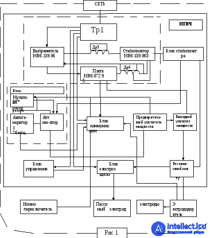
4.2. A simplified functional diagram of the device is shown in Fig. 1.
4.2.1. The self-oscillator generates sinusoidal oscillations at a frequency of 1,76 MHz, which are fed through an attenuator to the power amplifier.
4.2.2. The attenuator serves as the power level regulator in the HF source unit and simultaneously (in the «Coag», «Mixed» modes) as an amplitude modulator of the HF oscillations taken from the self-oscillator. The modulating voltage is supplied from the multivibrator.
4.3.3. The multivibrator generates rectangular pulses.
a) in the «Coag – mode, with a repetition rate of 22 kHz and a duty cycle of 3-0,5.
b) in the «Mixed» mode - with a repetition rate of 66 kHz and a duty cycle of 2.
4.2.4. The power amplifier is an externally excited HF current generator. The gain of the power amplifier at the optimal generator load is not less than 20 dB.
4.2.5. An HF signal is taken from the output of the power amplifier and is fed to the electrodes through a resonant circuit as well as the electrical protection unit of the HF source unit and the electrode holder.
The signal generated by the HF source unit is:
a) in the «CUT»-mode - continuous oscillations with a frequency of 1,76 MHz;
b) in the «Coag» and «Mixed»-modes - radio pulses with the parameters given in items 6-9 of Table 1.
4.2.6. Relay P1 of the HF source unit connects the output of the power amplifier to the electrode holders with the active electrodes.
4.2.7. The control and switching units make it possible to:
a) switch the device on and off from the mains supply;
b) switch the operating modes of the device;
c) connect the output of the HF source unit to one of the electrode holders, as selected;
d) manually set the required power level of the HF current supplied to the electrode holder.
4.2.8 For ease of use of the device, provision is made for switching on each of the modes – «Cut», «Coag», «Mixed»- with simultaneous application of HF voltage to the electrodes by means of the pedals of the foot switch (MB4.255.005); as well as connection of the HF source unit output to the given electrode holder and adjustment of the power level, not only from the front panel of the HF source unit, but also by means of buttons located on the handle of the electrode holder.
4.2.9. Along with what is specified in item 4.2.7, the switching unit of the device provides interlocking of the HF current switch-on (see item 11 of Table1 ).
4.2.10. The control unit makes it possible to carry out visual monitoring of the state of the device in the cases specified in items 4.2.7 (except 4.2.7c), 4.2.8 and 4.2.9.
4.2.11. The power supply unit generates, from the 220 V 50Hz mains voltage, the supply voltages for the self-oscillator circuits, the control and indication units, and the power amplifier.
4.2.12. To increase the efficiency of the HF source unit, the device has automatic regulation of the supply voltage magnitude of the output stages of the power amplifier.
4.2.13. To ensure the linearity of the load characteristic of the HF current generator over a wide range of loads (item 5 of Table 1), the device has automatic regulation of the amplitude of the HF voltage supplied from the attenuator output to the power amplifier input.
4.2.14. To implement what is specified in items 4.2.12 and 4.2.13, part of the HF power in the output device is used to generate two control signals, one of which is fed to the power supply unit, and the other to the attenuator.
4.2.15. The electrical protection unit isolates the passive electrode circuit from the device housing with respect to DC.
4.3. Design of the ESU-500-4 unit.
4.3.1. The external appearance of the device is shown in Fig.2 (front view) and Fig.3 (rear view).
4.3.2. The main indication controls, provided with corresponding labels, markings and a scale, are brought out to the front panel of the HF source unit.
4.3.3. The electrode holders, the passive electrode and the foot switch have cables and are connected to the HF source unit through corresponding connectors.
4.3.4. Connectors are installed on the rear panel for connecting two electrode holders and one passive elec-
+13

Comments