Lecture
This chapter will cover some of the components of the motion and drive systems that can be used in the construction of robots. Some circuits of similar components will be discussed in this chapter, other variants of the design of motion patterns and drive will be discussed in the following chapters. We will focus on the following structures: air muscles, nitinol wire, stepper motors, DC motors with gears, servomotors and solenoids.
Air muscles
Aerial muscle is a simple device proposed by JL McKibben in the 1950s. Like a biological prototype, the air muscle shrinks when activated. An interesting fact is that the air muscle is a fairly accurate copy of the biological muscle of the prototype, which allows researchers, by attaching these muscles to the skeleton points corresponding to the position of the “living” muscles, to simulate low-level biomechanical and innervation processes characteristic of biological muscle. In the published literature, such constructs are also called McKibben air muscles, MacKibben artificial pneumatic muscles, and “Rezinomyshimi”. I will use the name "air muscle".
Application
Air muscles are used in robotics, biomechanics, the creation of artificial limbs and industry. The main reason that experimenters and amateurs willingly use the air muscles is the simplicity of their design and ease of use in comparison with conventional pneumatic cylinders. The air muscles have a low weight, a “flexible” design and a high ratio of the force developed by them relative to their own weight (400: 1); they withstand longitudinal twisting, do not require parallel fastening of the ends, and can be bent by an external stop without disturbing the operation.
The principle of the air muscles
The air muscle consists of two main parts: the inner tensile soft rubber tube and the outer mesh cellular braid (sleeve), made of nylon (see. Fig. 4.1). The rubber tube is called the “internal bubble” and is enclosed inside the braided sleeve.
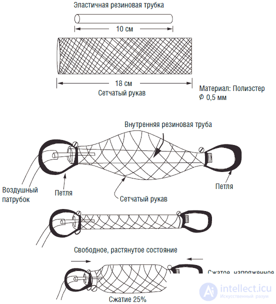
Fig. 4.1. The device and the work of the air muscles
Other components include an air tube at one end of the rubber tube and two loops at each end of the air muscle, allowing you to attach the muscle to the rest of the structure.
When pressure is applied to the internal bubble, it expands and presses from the inside onto the walls of the braided sleeve, which causes an increase in its diameter. The physical characteristics of the sleeve are such that its longitudinal contraction is proportional to the increase in its diameter, which causes the appearance of a contraction force in the air muscle.
It should be noted that for proper functioning of the muscles in a state of "rest", it must be stretched or loaded. Otherwise, the compression effect will not be pronounced. As a rule, such air muscle structures are able to contract up to 25% of their original length.
Nitinol wire
Nitinol is an alloy belonging to a class of materials with a "memory" of the form. Nitinol is usually produced in the form of wire. When heated, the material can be reduced to 10% of the original length. Such a contraction is capable of producing linear motion. In addition to the property of reduction, this alloy has the property of "memory".
The memory effect is a unique feature of this alloy. When heated to the temperature of the critical transition, the alloy automatically acquires the initially specified shape. The process of setting the original shape that the material “remembers” is called a thermal annealing procedure. The alloy is forced to the required form and subjected to an annealing process at temperatures above the critical. Such a process leads to a change in the crystal lattice of the alloy. After that, for any increase in the temperature level above the critical material, the material “remembers” the original shape given to it. A product made from such a material can be bent or twisted, but it will surely take its original shape with critical heating.
These unique properties are determined by the structure of the crystal lattice of the alloy. Return force can reach 1500 grams per square. see. It is unlikely that someone will use the material of such a large cross section. Even a rather thin wire is capable of producing a very large force. For example, a wire with a diameter of 6 mm creates a return force of 350 grams.
The volume of the nitinol wire, while reducing to the 10% level, remains constant. As it shrinks, its diameter increases proportionally, ensuring constancy of volume.
The simplest way to heat a nitinol wire is to pass an electric direct current through it (see Fig. 4.2). However, prolonged passing of direct current can lead to the destruction of the wire due to its uneven ohmic heating. Damage to the wire when heated and maintained in a heated state can be avoided by using a pulse-width direct current source.
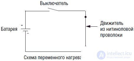
Fig. 4.2. Butterfly with nitinol wire
Some robot designers use nitinol wire in a motorless six-legged moving robot drive. The robot is indeed able to move, but it does so extremely slowly, since the cycle of heating and cooling the nitinol wire takes considerable time. The design of such a six-legged "crawling" robot is very light (it weighs a few ounces), but it has enough power to carry "its own" power source.
For six-legged “crawling” robots, the use of nitinol as a drive is hardly justified, but it finds many other interesting applications in the construction of robots. In order to learn more about the remarkable properties of this material, let's see how nitinol's ability to reduce is used in some commercial toys. In fig. 4.3 shows a mechanical butterfly, the wings of which are driven by a nitinol wire. As an interesting illustration of the principles of robotics, such a butterfly can be connected to a solar-powered power source.
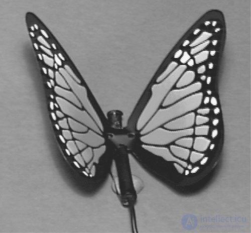
Fig. 4.3. Butterfly with nitinol wire
In fig. 4.4 shows a demonstration device - a moving ball. The nitinol drive makes about 20,000 cycles per day and is able to work for many years.
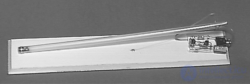
Fig. 4.4. Ball-Rocket Model
Nitinol wire loops can be used to create a spin. In fig. 4.5 depicts such a simple "thermal" propulsion. Each wheel has a groove in which is nitinol wire. For better thermal conductivity, the smaller wheel is made of brass. When a smaller wheel is placed in water, it begins to rotate. Such a thermal propulsion can work from the sun. If you focus the sun on a small wheel with a 3-inch magnifier, the device will start working.
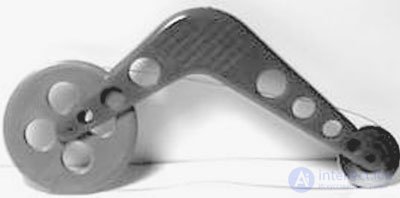
Fig. 4.5. Heat engine
Nitinol can also be used in push-button type mechanical switches, for example, as a drive for small air valves or in other mechanisms that require linear movements.
Solenoids
The solenoid is an electromechanical device (Fig. 4.6). The standard solenoid has a winding with a wire and an internal movable metal core. When voltage is applied, the magnetic field of the winding draws in or pushes the core. The core can be mechanically connected to the parts of the robot that require movement.
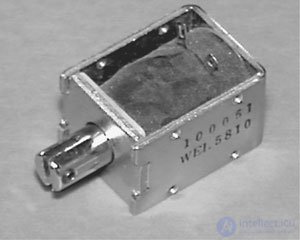
Fig. 4.6. Solenoid
Ring solenoids
The ring solenoid is different from the usual one (see. Fig. 4.7), that instead of a linear solenoid, it produces a rotational motion. Ring solenoid can be used in the design of a robot fish (see Ch. 13).
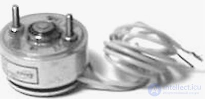
Fig. 4.7. Ring solenoid
Stepper motors
Stepper motors can be used for moving, moving, steering and positioning. Such devices are used as integrated components of many commercial and industrial computer-controlled systems. In home PCs, stepper motors can be found in drive drives and in printers.
The uniqueness of stepper motors is that they can be controlled using digital devices. Such engines can carry out turns on precisely set angle. This property makes stepper motors ideal for linear and circular positioning tasks. The widespread use of stepper motors in industry causes a wide range of models in shape, size and other properties (see fig. 4.8А).
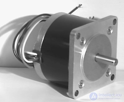
Fig. 4.8A. Stepper motor
When voltage is applied to a standard electric motor, its rotor begins to rotate continuously. The speed and phase of the rotor rotation are a function of voltage, engine load and time. Determining the exact phase (position) of the rotor in this case is impossible.
In contrast, the stepper motor is powered by a series of electrical pulses applied to the motor windings. Each pulse applied to the windings turns the rotor at a strictly defined angle. Such a turn is called a step, hence the engine received the name of the stepper.
There is no single step size for stepper motors; devices with different angles of rotation by one step (impulse) are produced. The nominal value of such a step depends on the nature of the application of the engine. The angles of rotation must be specified in the device specifications. You can find stepper motors with angles of rotation from fractions of a degree (for example, 0.72 °) to tens of degrees (for example, 22.5 °)
Stepper motor control circuit
In fig. 4.8B shows the control circuit of a stepper motor. Uses a unipolar six-pin motor. The U1 IC is a voltage-controlled 555 series timer, which, in the generation mode, produces rectangular clock pulses to pin 3. The U2 IC of the UCN5804 type is a stepper motor controller. Clock pulses arriving at pin 11 of the IC UCN5804 rotate the rotor of the stepping motor, with each pulse corresponding to one pitch. Increasing the frequency of clock pulses leads to an increase in the speed of rotation of the stepping motor.
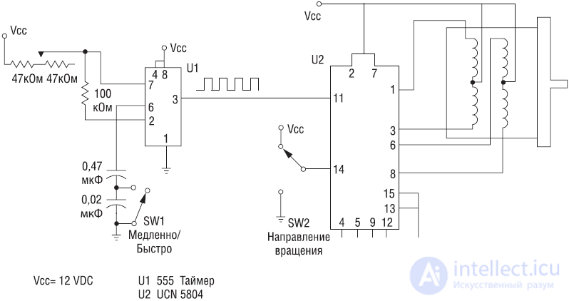
Fig. 4.8B. Stepper motor control circuit
In this simple scheme, the clock pulses are produced by the 555 timer. Such pulses can be generated using a microcontroller (see Chapter 6) or a photosensitive neuron (see Chapter 5). The SW1 switch changes the clock / pulse range slowly / quickly. Switch SW2 can change the direction of rotation of the motor rotor.
Stepper motors can be used to create a robot platform (see Chap. 10).
Servomotors
Servomotors are DC motors equipped with gearboxes and a position control feedback system. For amateur purposes, these motors are used to control the position of controls in radio-controlled models. The shaft of this motor can be rotated or held at angles of at least 90 ° from the middle position.
Due to the wide use of such devices in home-made designs, their manufactured range is quite diverse (see Fig. 4.9). There are large servos used in industry, but they are quite expensive for amateur use. In this book we will use small and inexpensive motors for amateur purposes.
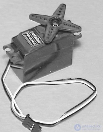
Fig. 4.9. Servomotor
The servomotor has three outputs. Two of them are supplied with a supply voltage from 4 to 6 V. A positioning signal is fed to the third output. The positioning signal is a chain of rectangular pulses with a duration of 1 to 2 ms. Accordingly, the pulse corresponding to the average position will be equal to 1.5 ms. The pulses are fed with a frequency of about 50 per second (50 Hz), i.e. the time between pulses is of the order of 20 ms. Such an “average” impulse will cause the motor shaft to turn to the middle position ± 45 degrees.
The rotation of the servo motor shaft is limited to 90 degrees (± 45 degrees from the middle position). A pulse with a length of 1 ms will cause the motor shaft to turn left until it stops (see fig. 4.10), while a pulse of 2 ms will cause a similar turn to the right. By varying the length of the pulses within 1–2 ms, it is possible to achieve rotation of the motor shaft at any angle within the specified interval.
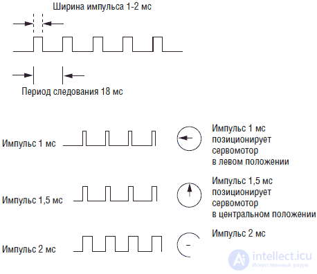
Fig. 4.10. Control pulses for servomotor
It may seem that the generation of such pulses is a rather complicated task. In fact, it is not. To control the PIC servo motor, the 16F84 microcontroller uses only a few simple commands. Such a PIC can control eight servomotors simultaneously. Another convenient method for controlling servos is the use of R / C systems. An alternative to this is to create your own control scheme.
Making such a scheme is not as difficult as it may seem at first. In fig. 4.11 shows the use of a dual timer type 556 to control the servo motor. Circuit 556 has two independent timers. For a better understanding of the operation of the circuit, look at the circuit shown in Fig. 4.12, where two separate 5555 series timers are used. The first timer is in the generation mode and generates negative rectangular pulses with a duration of 1 ms with a frequency of 55 Hz. This timer is connected to the second 555 series timer included in the one-shot circuit.
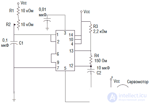
Fig. 4.11. Servomotor control using IC 556
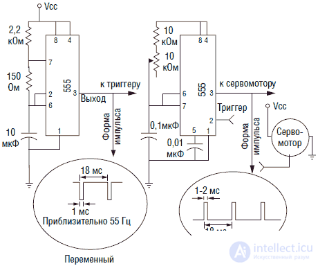
Fig. 4.12. Servomotor control using IC 555
When a negative pulse appears at pin 1, the one-shot generates a positive pulse at pin 5. The width of the output positive pulse can be changed using a 10 kΩ potentiometer. Depending on the type of servomotor used, it may be necessary to select the resistance values R1 and R2 in Figure 4.11. Remember that the servomotor may have internal angle stops, and do not apply excessive force if the motor is “stuck”.
Practical work with servomotors showed that turning the motor shaft to the extreme allowable positions requires pulses of less than 1 ms long or more than 2 ms.
As you gain experience with servomotors, you may want to use them at large angles of rotation (within 180 °), which will require expanding the range of control pulse times.
However, before taking such steps, you have to understand that when the control signal is supplied outside the range of angles of rotation of the servomotor, the motor shaft, reaching the extreme position, will be rested against the internal limiter, trying, nevertheless, to turn at a given angle.
For example, you have a servomotor that requires pulses of 2.8 ms in length to rotate to the extreme right. If the servomotor rotates normally, then everything is fine. Suppose you replace it with another motor, the control range of which is limited to a pulse length of 2.5 ms. If you continue to apply a pulse with a length of 2.8 ms, the servomotor will try to turn a greater angle than it physically can. As the rotor rests against the limiter, an additional current will flow through the motor, which the motor itself can burn.
The problem usually occurs when replacing the servomotor. Very often, a replaced motor has a slightly different control pulse range. It is necessary to take as a rule: if the range of applied pulses leaves the zone of 1–2 ms, it is necessary to check the servomotor in extreme positions for sticking.
Servomotors are used in the walking robot described in ch. 11. To control servomotors used PIC microcontroller. Applications of servomotors and PIC microcontrollers are described in ch. 6
DC motors
DC motors for amateur design can be used to move and move robots' structures (see Figure 4.13). Most of these engines are characterized by high rotor speed and low torque. The designs of robots, on the contrary, require high torque at low speeds. Gearboxes can be used for this (see fig. 4.14). The gearbox is characterized by a gear ratio, i.e. the ratio of the rotational speeds at the input and output. For example: an engine with a rotational speed of 8000 rpm is connected to a gearbox having a gear ratio of 1000: 1. What will be the speed at the output of the gear? 8000 rpm: 1000 = 8 rpm Accordingly, the torque will increase. It can be expected that the torque will increase to the same extent that the speed has decreased. Practically, since the efficiency of any device is always less than 100%, the torque will be slightly lower due to losses.
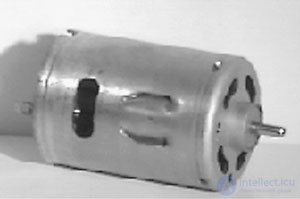
Fig. 4.13. DC motor
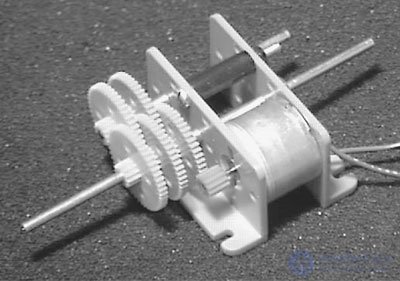
Fig. 4.14. Dc motor with gear
Some DC motors are structurally combined with a gearbox and are called motors with a gear head (see. Fig. 4.15).
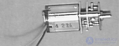
Fig. 4.15. Dc motor with gearbox head
Bridge DC motor control circuit
When designing a robot, it is desirable to have a simple control circuit for switching it on and off. In addition, the required reverse direction of rotation of the engine. The bridge control scheme satisfies these requirements.
It should be understood that the term "DC motor" also refers to motors equipped with gearboxes or having a gear head.
Мостовая схема состоит из четырех транзисторов (некоторые используют МОП полевые транзисторы. Я использую биполярные Дарлингтоновские NPN транзисторы). В некоторых схемах используются транзисторы PNP и NPN проводимости. В любом случае транзисторы используются в ключевом режиме (см. рис. 4.16А). Когда ключи SW1 и SW4 закрыты, двигатель вращается в одном направлении. Когда закрыты ключи SW2 и SW3, двигатель вращается в противоположном направлении.
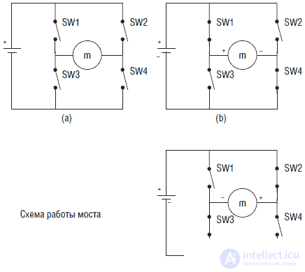
Fig. 4.16. Мостовая схема на переключателях
При правильной коммутации ключей мы можем изменить направление тока, протекающего через двигатель, на противоположное, что вызовет изменение направления вращения вала двигателя. Транзисторная схема моста, управляющего двигателем, показана на рис. 4.17. Подобная схема использована в гл. 5 в схеме сенсора робота-тестера.
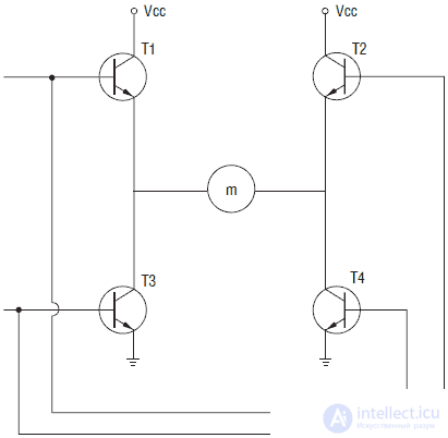
Fig. 4.17. Мостовая схема на транзисторах
Pulse Width Modulation (PWM)
Мостовая схема обеспечивает включение-выключение двигателя постоянного тока и управляет направлением его вращения. К этим функциям может быть добавлена функция управления частотой вращения двигателя с использованием широтно-импульсной модуляции (ШИМ). Форма ШИМ сигнала приведена на рис. 4.18. Высокий уровень сигнала ШИМ соответствует включению двигателя, низкий уровень его выключает. Поскольку частота импульсов ШИМ очень велика, то напряжение на двигателе может быть определено как среднее значение длины импульса к периоду следования (скважность импульса). Чем больше длина импульса, тем больше среднее напряжение. Среднее напряжение лежит в пределах от нуля до напряжения питания, и, таким образом, ШИМ эффективно управляет скоростью вращения двигателя.
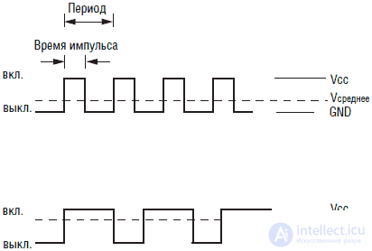
Fig. 4.18. Широтно-импульсная модуляция (ШИМ) для управления мостовой схемой
Двигатель является индуктивной нагрузкой. В моменты включения/выключения возникающее переходное напряжение, генерируемое обмотками двигателя, может повредить полупроводниковые части моста. Для гашения этого напряжения используются защитные диоды, включенные параллельно транзисторам, как показано на рис. 4.19.
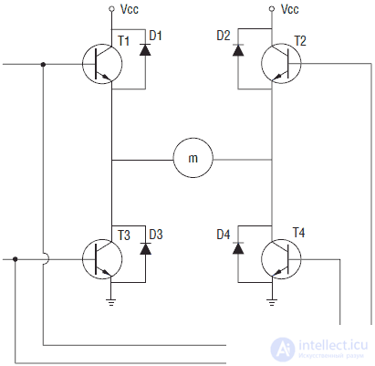
Fig. 4.19. Транзисторная мостовая схема с защитными диодами
Защитный диод гасит обратное переходное напряжение на землю, что эффективно защищает переход транзистора, к которому подключен диод. Защитные диоды должны быть рассчитаны на нормальный ток, потребляемый двигателем.

Comments