Lecture
The idea of creating such a robot was originally put forward by Richard Weit from North York, Toronto. Richard built a robot looking for a source of light enclosed in a transparent sphere (ball). Then, more recently, Dave Storakuyu from Calgary, Canada, so to speak, “raised this ball” and built a series of mobile robots — solar orbs searching for sources of light.
Two curious qualities possessed by such robots can be noted (see Fig. 12.1). The first of these is the way to travel. The gearbox is placed inside the ball. One of the ends of the gear shaft is tightly attached to the inner side of the surface of the transparent sphere. The rigid mounting of the shaft of the gearbox prevents its rotation, which forces the gearbox itself to rotate. The gearbox has a fairly large weight, which moves the center of gravity of the sphere forward. For this reason, the sphere itself is rolling forward.
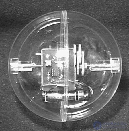
Fig. 12.1 Robot - Solar Ball
At rest, the center of gravity of the gearbox is at the bottom dead center (the bottom position of the gearbox), and the ball is at rest, i.e. it resists rolling. When you turn on the gear, it begins to rotate inside the ball. This rotation moves the center of gravity of the ball forward, and the ball thus rolls in the forward direction.
The second quality relates to the method of powering the gearbox design. Initially, the solar robots had an onboard power source, which made it possible to supply power to the gearbox in an intermittent mode (this was described in more detail in Chapter 3). The on-board power supply consists of a solar cell battery, a main capacitor and a trigger or low-frequency generating circuit. When illuminated by the luminous flux, the solar battery starts charging the main capacitor. When the capacitor voltage reaches a threshold value, the triggering circuit passes the accumulated charge through a high-efficiency motor connected to the gearbox, which causes the robot to move slightly forward.
This robot design uses a similar gearbox design, but two AA elements are used to power it. The disadvantage of batteries is the need to replace them after use. However, their advantage is that the power to the robot circuit is constantly supplied, which allows us to easily study its behavior (mainly phototropism), movement and movement.
In the original design of the robot to study these effects required a method of slow motion. Depending on the light level, each charge of the capacitor takes several minutes. When the charge flows through the engine, the robot rolls forward slightly. For example, 10 hours of movement of the original model of a solar robot is compressed in a few minutes when studying this design.
This robot does not require electronic control circuits for the on-board power source, however, it also needs a light switch. The scheme shown in Fig. 12.2, controls the supply voltage from the battery to the gear motor. The scheme determines the level of illumination, "visible" by the robot. If the level of illumination is high enough, then the scheme includes the engine. The threshold of the light level can be adjusted using a variable resistor V1.
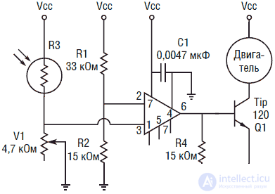
Fig. 12.2. Electrical circuit diagram of the solar globe
Gearbox design
Before we begin to manufacture the robot, let's look at the design of the gearbox (see. Fig. 12.3). The physical dimensions of the gearbox are smaller than usual and are easier to mount inside the sphere. The gear ratio of the gearbox is 1000: 1. The greater the gear ratio, the slower the robot will move.
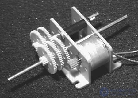
Fig. 12.3. Gearbox with a ratio of 100: 1
In the prototype used gear with a gear ratio of 1000: 1. You can use any other gear that fits in a transparent sphere with an inner diameter of 140 mm. Choose a gear with a large gear ratio, which will reduce the speed (7 rpm).
Robot design
The first thing you need to pay attention to the device. It must be transparent and of sufficient size to accommodate the gearbox and electrical circuits. In the prototype was used a spherical body with a diameter of 140 mm. The half-spliced transparent spheres are sold in many stores that specialize in consumer goods. Such areas are used by amateurs to place various “weekend” handicrafts in them. If you are unable to purchase such a sphere in a local store, you can order it in Images SI (see the list of construction details at the end of the chapter). The plastic case is fragile. Do not make your robot climb or descend the stairs, the hull may break, which will cause the structure to become unusable.
Separate the two halves of the case. First you need to accurately determine the geometric center of each hemisphere. At these points, the ends of the gear shaft will join. Determining the position of a center point may seem easier than it actually is. To find the center, I was forced to draw a circle around the perimeter of the hemisphere on paper, then draw a square around the circle with the sides touching the circle (see Fig. 12.4). Having a diagonal of the square, I found the geometric center of the circle. Then the hemisphere was placed on a circle pattern. If you hold your head directly in front of the sphere, you can visually identify the center and mark it on the sphere with a marker. I tried this method once or twice, but the results were unsatisfactory. In the end, I stuck the paper on plywood with a thickness of 1.5 mm and drilled a small hole in the marked center. Then I took a small pin 63 mm long and fixed it in the hole, making sure that it was perpendicular to the plane. Take the hemisphere by the rim and align its diameter with the circle drawn. The end of the pin will indicate the position of the center with great precision. Mark the center position first on one hemisphere, and then on the second.
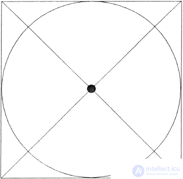
Fig. 12.4. Drawing for finding the center of the circle
The next step will be the manufacture of the locking device of the retainer inside the sphere, which will prevent the free rotation of the gear shaft inside the sphere. Since the shaft is fixed, this leads to the rotation of the gear itself inside the sphere. In this case, the center of gravity moves, and the robot moves forward. At the same time, the design of the detent shaft of the gearbox should provide, if necessary, the connector and connection of the halves of the sphere. The system I use is illustrated in fig. 12.5 and 12.6. For this purpose, I used the same type of transparent plastic from which the sphere was made, and you can make these parts from other materials, such as brass or wood.
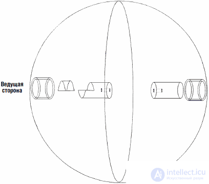
Fig. 12.5. Details of the drive of the transparent sphere
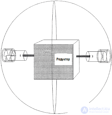
Fig. 12.6. The position of the gear inside the sphere
The first part is a small piece of tube with an outer diameter of 15 mm, an inner diameter of 12 mm and a length of 9.5 mm. This tube is glued to the center of the hemisphere at the point we noted earlier.
Half of the cut along the rod with a diameter of 12 mm and a length of 9.5 mm is glued inside the tube. This part can be glued into the tube before gluing the tube to the surface of the hemisphere.
Then cut a small piece of hard plastic core with a diameter of 12 mm. Saw it along the length of 9.5 mm and remove half. This can be done with a hacksaw or slot. First cut the gap to a depth of 9.5 mm, and then make a horizontal cut to remove one half. Check that the rod enters the entire depth of the tube 15 mm and is securely connected to the inner surface of the hemisphere. If this does not occur, file a semicircular end of the rod. At the other end of the rod, drill a hole in the center corresponding to the diameter of the gearbox shaft.
Note In the original version of the design, I made the fastening of the gearbox shaft to the hemisphere in the same way. Only when the construction was completed, I realized that this is not necessary. Split joint on the one hand was enough.
The mounting design to the second hemisphere is easier to manufacture. Glue a small piece of tube with an outer diameter of 15 mm and an inner diameter of 12 mm to the center of the hemisphere, using the marked mark. Cut a small piece of a rod with a diameter of 12 mm. Make sure that the rod is easily inserted into the 15 mm tube. If not, take a small piece of sandpaper of medium grain. Wrap the sandpaper 12 mm from the end of the rod. Strip the end of the rod by rotating it in an emery paper ring. Continue cleaning the rod until it is easy to enter from the tube opening. Then drill a hole in the other end of the rod corresponding to the diameter of the gearbox shaft.
It is necessary that the gearbox is located exactly in the center of the sphere. Insert the end of the gearbox shaft into the hole in the plastic rod. Insert the rod into the tube attached to the inner surface of the hemisphere of our ball.
Obtain the center position of the gearbox and note the depth at which the gearbox shaft enters the plastic rod. Remove the gearbox from the hole in the rod. Cook a small amount of epoxy glue. Apply epoxy glue to the shaft of the gearbox and insert it into the hole of the rod. Wait for the glue to dry before proceeding.
As soon as the glue dries, we must glue the second plastic rod on the opposite side. Insert the glued rod into the hemisphere. Insert another plastic rod into the opposite end of the shaft. Connect half the sphere for the first time. Notice the depth to which the gearbox shaft enters the plastic rod and add 3 mm to compensate for possible errors. Glue and let the glue dry. When splicing the second end of the gearbox shaft, make sure that the half of the sphere is properly closed.
Electrical circuit
The electrical circuit is an electronic switch controlled by the intensity of the light flux. When the average ambient light level is low (a threshold value adjustment is possible), the circuit turns off the power supply to the gear motor. The sensitivity threshold of the circuit is controlled by the variable resistor V1.
In the manufacture of the scheme is nothing complicated. If you do not want to purchase or manufacture a PCB, the circuit can be assembled and mounted on a breadboard.
Work scheme
The circuit contains an operational amplifier of a CMOS structure used as a voltage comparator. The comparator compares the values of the two input voltages. One of the voltages is called the reference voltage and is denoted Vop. This value is compared to the input voltage, denoted Vin. When the value of Vin. exceeds or falls below Vcn., the state of the comparator output changes.
Two input voltages are applied to pins 2 and 3 of the IC. Pin 2 (inverted input) is connected to a reference voltage source, formed by a voltage divider on resistors R1 and R2 and is approximately 1.5 V.
The photoresistor R3 forms, together with the variable resistor V1, another voltage divider, which is connected to the non-inverted input of the op-amp.
In this scheme of switching on the OU there is no feedback resistor between the OU output (pin 6) and one of its inputs, which allows the OU to operate in the maximum gain mode (open loop).
A CdS photoresistor is used as the light sensor. The photoresistor changes its resistance in proportion to the amount of luminous flux incident on its surface. CdS photoresistor has the greatest resistance in total darkness. With increasing light intensity, its resistance decreases. In this circuit, the CdS photoresistor is included in the voltage divider circuit. The change in the resistance of the CdS photoresistor leads to a change in the voltage drop across the variable resistor V1 connected to pin 3 of the op amp. As the illumination flux increases, the resistance of the CdS photoresistor decreases, and the voltage drop across the variable resistor V1 increases accordingly. Increasing the voltage drop means increasing the voltage at pin 3. With the help of a variable resistor, you can set the level of the comparator triggering for different values of illumination.
Making the scheme is not a big deal. You can install on a breadboard with point-to-point soldering. You can use a printed circuit board from a set or make it yourself. The circuit board drawing is shown in Fig. 12.7. The location of parts on the printed circuit board - Fig. 12.8.
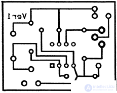
Fig. 12.7. PCB drawing
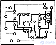
Fig. 12.8. The location of the parts on the PCB
After the circuit is assembled, it is necessary to adjust with the help of a variable resistor V1 the desired level of illumination at which the circuit is turned on. Using crocodile clips, temporarily connect the circuit with the gear motor. The power supply of the circuit and the engine is provided by means of two AA elements, and the battery compartment for these elements is glued to the gearbox at the time of final assembly. Ensure that the battery compartment allows easy insertion and replacement of elements.
When setting the threshold level of illumination, use low enough levels. Otherwise, while the robot is moving across the floor, it will stop each time, falling into the shadow if the threshold value of the light level is too high.
Final assembly
After adjusting the threshold for the light level, you can proceed to final assembly. Glue the battery compartment for the AA elements to the gearbox housing, carefully making sure that the glue does not get on the gears of the gearbox. Then glue the board with the scheme, also making sure that glue drops do not get into the gear mechanism. Connect power supply. At this point, the gearbox may begin to rotate. To properly assemble, move the mechanism to a darker room to turn off the circuit. Place the structure inside the sphere.
Now bring the robot to the light. Gearbox should turn on. Place the robot on the floor surface. The robot must move forward or in the direction of the light source. If the robot moves in the opposite direction, stop it, remove the gearbox and the electronics board and swap the wires to the engine.
Movement
When I began to observe the "behavior" of the robot, I was extremely surprised. Initially, I thought that the robot would easily fall into the “traps”. It turned out that it is not. When the robot reaches the corner and stops there, the rotation of the gearbox inside starts to swing it up and to the side, moving its weight to the “upper dead center” and thus pushing the robot out of the corner.
Design improvement
In the original version, I planned to use the steering mechanism so that the robot follows the light source. However, it turned out that the small steering gear does not have enough weight to quickly turn the robot in some direction. In the process of a long movement, other factors (relief, presence of obstacles, etc.) strongly influence the direction of movement. For this reason, I abandoned the steering mechanism. Nevertheless, the improvement of the design can be carried out in this direction.
Introduction of an additional mode of behavior
The robot is initially at rest, but at a certain level of illumination it enters the “active” phase. We can introduce another behavioral level (power supply) by adding some components (two solar panels and two control diodes) and an additional comparator circuit. The second comparator will turn off the engine at a sufficiently high level of ambient light, including the mode of charging AA elements from the solar battery. In this case, NiCd batteries should be used as AA cells.
In fig. 12.9 the scheme of behavior of the robot is shown. When the light level is low, the robot is turned off, or we can say that it is in a “rest” state. As the level of illumination increases, it reaches a point when the engine turns on and the robot enters the “search” mode. With a further significant increase in the level of illumination, at some value, the second comparator will turn off the engine, and the NiCd batteries will be charged from the solar battery, providing a “power” mode.
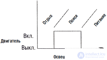
Fig. 12.9. The organization of behavior on "levels"
If you decide to build such a system of "power", then you need to make sure that the current consumed by the comparators does not exceed the current produced by the solar battery. Otherwise, charging NiCd batteries will be impossible.
List of parts for the manufacture of the robot-solar globe
• (1) 140 mm transparent plastic sphere (see above text of this chapter).
• (1) Gearbox (see above text of this chapter)
• (1) Solid plastic core 150 mm long with a diameter of 12 mm
• (1) Plastic tube 75 mm long, inner diameter 12 mm, outer - 15 mm
Electronic components
• (1) 5V op amps CMOS structures ALD 1702 or equivalent
• (1) 33 kΩ resistor, 0.25 W
• (1) CdS Photoresistor
• (1) 4.7 kΩ Trimmer Resistor
• (2) 15 kΩ resistor
• (1) Capacitor 0.0047 uF
• (1) TiP 120 NPN Darlington Transistor
• (1) Development board

Comments
To leave a comment
Robotics
Terms: Robotics