Lecture
To ensure the functioning of the robots need power - most robots use electricity for this. To provide mobile robots with autonomous power supply, there are two sources: electric batteries and photovoltaic cells. In the near future, a third source, fuel cells, will appear to power the robots.
Photoelectric elements
Photovoltaic cells, commonly known as solar cells, generate electrical energy when exposed to sunlight. Standard solar cells are extremely low-power: with a potential difference of about 0.7 V, they give a current of a few milliamps. To obtain an acceptable power level, the cells are connected together in solar panels (batteries). In robotics, in order to provide direct power for robots, they use a series and parallel connection of solar cells.
In order to ensure the functioning of a solar-powered robot, its dimensions should be minimal while maintaining the required range of functions. Accordingly, light and high-strength materials and electronic circuits that consume little energy should be used.
The lighter the weight of the structure and the consumption of electrical energy, the more promising is the use of solar cells. However, low weight and economical power consumption are important in the manufacture of any robot. Such light, low-power robots are able to work longer with a given power supply capacity than their heavier and more energetic “voracious” fellows.
Solar cells can serve as a source of secondary power for the robot, recharging its batteries. Such a combined power supply reduces the power requirements of solar cells compared to directly powered by a solar cell robot. However, in this case, the robot will actively operate only part of the time, and for the rest, it will recharge its batteries.
We can also use solar cells in combination: as sources of direct and secondary power. We will try to make a device that is commonly called a solar engine. The functional diagram is very simple. Its main components are: a solar battery, a storage capacitor and a trigger circuit. The solar battery under the action of light begins to charge the high-capacity storage capacitor. The battery / capacitor system provides electricity for the rest of the circuit. As the capacitor charges, the voltage across it increases and at some point it begins to exceed the specified trigger threshold of the trigger circuit. As soon as the trigger is triggered, the capacitor begins to discharge through the main load. Then the cycle repeats. Devices such as a solar motor can be used in various robotic structures.
Building a solar engine
The solar engine is often used as an on-board power source used in BEAM robots, which are often called “living” robots (see the discussion on BEAM robots in Chapter 8). Solar engines got their distribution thanks to the work of Mark Tilden, who designed the first such engine. Another inventor was Dave Stokivov from Canada, who built his version of the solar engine to power the “dancing” robot. I liked these developments so much that I decided to make my own version of the solar engine. In the process, I was able to come up with a new version of the scheme, which increased its efficiency in comparison with the original version.
In fig. 3.1 shows the electrical circuit of the solar engine. Consider her work. The solar battery charges a 4700 microfarad capacitor. As the capacitor charges, the voltage on it increases. A single junction transistor enters the oscillation mode and sends a pulse that triggers the thyristor. When the thyristor is open, all the energy stored in the capacitor is discharged through a motor with high efficiency. During the discharge of the capacitor, the motor rotates. Then a stop occurs and the cycle repeats.
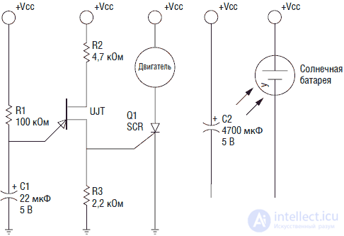
Fig. 3.1. Solar motor circuit
The scheme of the solar engine is simple and uncritical to the parts used. It can be assembled on a breadboard, the conclusions of the elements are connected by conductors. For those who want to assemble the engine on a printed circuit board - the drawing of the board is shown in fig. 3.2. A printed circuit board is included in the set to create a solar engine. In fig. 3.3 shows the layout of parts on the PCB. In fig. 3.4 posted photograph of the engine assembly.
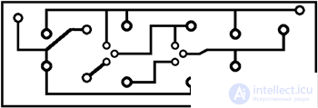
Fig. 3.2. PCB drawing
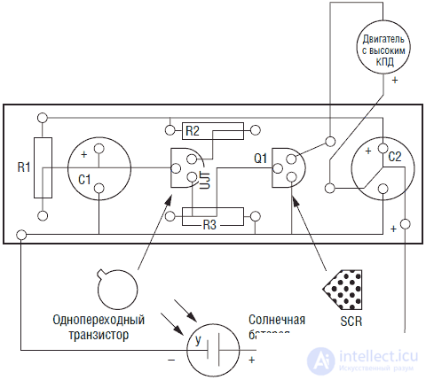
Fig. 3.3. Placing parts on the PCB
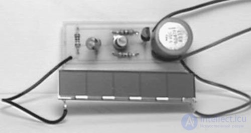
Fig. 3.4. Solar motor assembly
• transistor 2N2646 (1)
• thyristor 2N5060 (1)
• 22 μF electrolytic capacitor (1)
• 4700 uF electrolytic capacitor (1)
• DC motor
• solar cell element (2)
• printed circuit board
• 200 kΩ 0.25 W resistor
• 15 kΩ 0.25 W resistor
• 2.2 kΩ 0.25 W resistor
High efficiency engineNot all electric motors have high efficiency. For example, small DC motors from radio sets, as a rule, have low efficiency. To determine this, there is a simple procedure. Use your fingers to rotate the motor axis. If the rotor rotates smoothly and continues to rotate when you release the axle, then it may be a high-efficiency motor. If the rotor axis turns in spurts, and you feel resistance, then, most likely, the efficiency of such an engine is small.
Features of the design of the solar engineThe solar cells used in the device have high efficiency and high output voltage. For solar cells, typically, the output voltage is in the range of 0.5–0.7 V at different currents, which depend on the size of the element. The solar cell used in this scheme gives a passport voltage of about 2.5 V, but without a load it charges the capacitor to 4.3 V.
I am sure that some of those who want to build such a scheme are already thinking about the possibility of a faster charge of capacity through an increase in the number of solar cells. This thing should not be done. Additional elements will actually increase the charge current and, accordingly, reduce its time, but only in the first cycle. In order for the thyristor to close and start a new cycle, it is necessary that the current flowing through the thyristor should stop (or become very small). And if the solar battery will give a sufficiently large current, the thyristor will “stick” in the open state. Accordingly, all battery energy will be dissipated through an open thyristor at the connected load. The capacitor will not charge and the circuit will exit cyclical mode.
For proper operation, the details of the scheme are specially selected. The only component that allows variations within a wide range is a storage capacitor. Smaller capacitance values will lead to a faster charge-discharge cycle. Large values of capacitance or the use of several capacitors will lead to the accumulation of a larger amount of energy and, consequently, the accomplishment of more work, however, it should be remembered that when using such capacitances, the charge-discharge cycle can be much longer.
ApplicationThe solar motor circuit can find a lot of new and unexpected applications, for example, as an onboard energy source of a solar racing car, a power source for a relay, a buoy assembled on LEDs, a motor for moving a robot or, as shown in Fig. 3.5, the device turning the American flag.
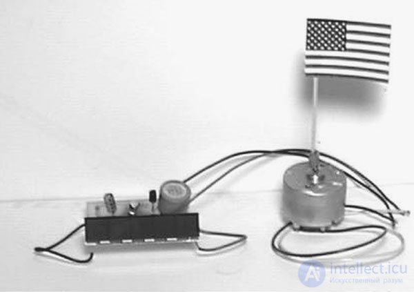
Fig. 3.5. Turning the flag using a solar motor
The attractiveness of the solar engine is that it can work "forever" until one of its parts fails, which can happen over the years.
Batteries
Batteries without any doubt are the most frequently used power sources for robots. Batteries are so familiar that everyone takes it for granted. Understanding the device battery will help you choose the best type of battery for your design. This entire chapter is devoted to the description of various types of batteries.
Battery capacity
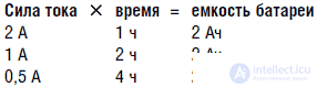
The capacity of any battery, regardless of its type, is measured in ampere hours, which means the product of the current in amperes or milliamperes and the time, expressed in hours, during which the battery is capable of delivering this current. This concept has a very simple physical meaning. Let's say the battery capacity is 2 Ah. This means that the battery is able to maintain a current of 2 A for 1 hour. If we reduce the current to 1 A, then the battery will “live” 2 hours. If you reduce the current to 500 mA, then the time will increase to 4 hours, respectively. Thus, the “life” of the battery was inversely proportional to the strength of the flowing current.
It is not difficult to write an arithmetic expression that determines the period of the battery life depending on a certain current strength. For example, suppose the robot consumes 0.35 A (350 mA). If a battery was used, which we have already talked about (2 Ah), then simply divide its capacity by the amperage (0.35 A) and we get the “life” of the design 5.7 hours. In fact, not so simple. Batteries give maximum power in an intermittent mode, which allows them to chemically recover in pauses. Constant load effectively uses the battery only in the case when it is small. In robotics, especially when using powerful motors or other similar components, the nature of the load is far from optimal. In this case, it is necessary to use higher capacity batteries.
Battery voltage
During the lifetime of the battery voltage changes. If you measure the voltage of a fresh alkaline element of type D (element 373), then it will be about 1.65 V. As the element is discharged, the voltage drops. The cell is considered “dead” when its voltage drops to 1 V. Typical discharge curves for zinc, alkaline, and nickel-cadmium batteries are shown in Fig. 3.6.
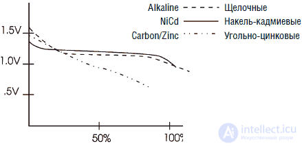
Fig. 3.6. Discharge curves of standard galvanic cells
Note that the voltage of a new nickel-cadmium cell battery is about 1.35 V. Although the initial voltage is lower, the discharge curve of such a cell is flatter compared to the carbon-zinc and alkaline cells, keeping at the level of about 1.2 V.
Galvanic cells
Electroplating cells are disposable batteries. Here we consider a class of batteries having a voltage on the cell of the order of 1.5 V. The batteries are designed in such a way that after working off their capacity they must be disposed of. When designing robots, frequent replacement of "dead" batteries can be quite expensive. However, the advantage of such batteries is that, as a rule, they have a higher specific electrical capacity than batteries. With a "one-time" use of the device (for example, "fighters" in the war of robots), the use of galvanic batteries may be preferable, because they give more power.
Classification of electroplating batteriesAs you may have guessed, there are several types of galvanic batteries. The difference between batteries is in the type of chemicals used to produce electricity. The choice of the type of battery is based on the criteria of the ratio of output power to the price of the battery, the battery “life” time, the temperature range of use, the discharge curve and the maximum output current.
Zinc carbon elements. Zinc-carbon elements are located on the "lower" end of the battery row. Since their invention by Georges Leclanche in 1868, they have not undergone significant changes. The zinc carbon cell has a low specific capacity (of the order of 0.05–0.1 Wh per cubic centimeter), does not withstand more currents, has a sloping discharge curve and is “afraid” of low temperatures. Such elements are cheap enough, but are obsolete.
Alkali manganese elements. Such elements in everyday life are called alkaline batteries. Their specific capacity is higher (0.1–0.15 Wh / cc), they have improved temperature characteristics, a gentler discharge curve and a moderate price.
Lithium elements. Lithium cells are by far the best. Their specific capacity is 0.5 Wh / cc. cm, they have excellent temperature characteristics for both high and low temperatures, they retain their charge for a very long time (about 15 years) and also have a low weight. The disadvantage is the relatively high price of this item.
Rechargeable batteries
Rechargeable batteries have the ability to recharge. The most widely used are acid and nickel-cadmium (NiCd) batteries. We will begin the review with the latter.
One of the drawbacks of NiCd batteries is a fairly low voltage — 1.2 V per cell (can), which is below the normal voltage of galvanic cells — 1.5 V. The effect becomes even more noticeable when several cells are connected in series. For example, a 6-element NiCd battery on “9V” can actually produce no more than 7.2 V.
Automotive acid batteries are unsuitable for use in robotics. The reason is that in such batteries the discharge to “zero” is technologically unacceptable. Such batteries can release a high current for a short time (starting the car with a starter) and after that should be immediately recharged.
The residual electrical energy contained in the battery after it is fully discharged is called deep discharge. There are acid batteries that can withstand deep discharge, they are used, for example, in a combination of power systems based on solar cells, but the price of such batteries is high. When designing robots, it is recommended to use batteries that can withstand deep discharge cycles.
Although batteries are more expensive, but with long-term operation, their use brings significant savings. Usually batteries allow from 200 to 1000 cycles of "charge-discharge". In many cases, a small charger can be built into the robot, making it unnecessary to remove the batteries from the device for charging.
Battery classificationNiCd batteries. The most commonly used sealed acid and NiCd batteries, the latter are more popular. Manufacturers claim that NiCd batteries can withstand from 200 to 1000 cycles of "charge-discharge", but these batteries quickly fail if the charging mode is not observed. The "life" of these batteries is in the range of 2-4 years. Fully charged NiCd batteries retain charge for 30–60 days.
NiCd batteries require charging current of the order of 10% of their electrical capacity. This means that a 100 mA current (1A / 10 = 100 mA) is required to charge a NiCd battery with a capacity of 1 Ah. The magnitude of the charging current is denoted for this case "C / 10".
NiCd batteries structurally require DC charging at a C / 10 level. Due to the inefficiency of this process, the required charging time for these batteries is 14 hours. Although manufacturers claim that you should not be afraid of overcharging the battery at the C / 10 current level, many engineers recommend switching to a lighter mode after 14 “regular” hours of charging at the C / 10 level. Light mode is determined from the ratio of 1/30 of the battery capacity. Easy mode to charge a battery with a capacity of 1 Ah will be 33 mA (1A / 30 = 33.3 mA).
Memory effect The disadvantage of NiCd batteries is the memory effect. If you start recharging the battery several times before it is fully discharged, then this level will be “memorized”. After that, there will be problems with the discharge of the battery below this level, which can lead to a sharp decrease in its capacity. To eliminate this problem, a special load must be connected to the battery for several hours. After the battery is completely discharged, it is charged in the usual way and restores its characteristics.
Acid batteries. Batteries with gel electrolyte (gel cells) are similar to car batteries. They are sealed, maintenance-free acid batteries. Note that such batteries are popular sizes D, C, AA, AAA and 9 V "Krona" on sale does not happen. They usually have larger sizes and can be used in large robots.
Gel elements have a wide range of output voltages from 2 to 24 V and a large range of currents. They can be charged with a constant voltage, subject to current limiting or DC, similar to NiCd batteries. The typical value of the charging voltage for each gel element is within 2.3–2.6 V. Initially, a significant current flows through the battery, which decreases during charging. To maintain the battery in a fully charged state, after the main charging process is over, a small “supporting” current (approximately C / 500) is passed through it.
Gel batteries differ from different manufacturers, so for proper charging you need to read the relevant instructions. A simple general purpose charger can be made based on the LM317 voltage regulator. A fixed voltage (2.3 V) is applied to the element at a DC value of C / 10. After the battery is fully charged, the DC source is disconnected, and an adjustable voltage source is connected.
Many gel batteries poorly "carry" a deep discharge. To prevent this, it is necessary to control the battery voltage under load. When the voltage drops below the recommended by the manufacturer - the battery needs to be charged.
Generalization
Most manufacturers of robots use alkaline-type galvanic cells and NiCd as working batteries.
Making a charger (charger) for NiCd batteries
NiCd battery chargers are cheap. Usually, making an external charger for popular battery sizes, such as AAA, AA, C and D, does not take much time and effort. The ability to design such a device will be useful to those who want to embed the memory in the robot. Unlike most cheap chargers, which continue to charge the battery with a current of the order of C / 10 even after it is fully charged, our device reduces the charging current to about C / 30 after the batteries are fully charged. This procedure is recommended for NiCd batteries and will help ensure their long-term performance.
The following information will allow you to make your own memory for a standard NiCd battery.
The charger is a separate unit, its connection diagram is shown in Fig. 3.7 for illustrative purposes. This scheme is easy to place in the body of the robot, and you will need a connector for connecting to the charger. In addition, a bipolar two-way switch is required, placed between the connector and the rest of the circuit. This switch connects the power supply (battery) either to the rest of the robot circuit or to the charger. De-energizing the robot is necessary because otherwise the battery charge current will decrease (see Fig. 3.7).
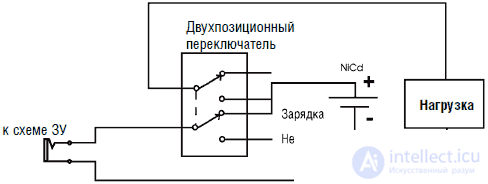
Fig. 3.7. On / Off switch that controls battery charge
The power supply of the charger can be made using either a conventional transformer or a portable power supply unit combined with a plug (such as used for powering players). I prefer the latter because it gives a constant current output. If you use a transformer, you will additionally need a mains fuse, a diode bridge, a smoothing capacitor, and connecting wires.
In any case, you must choose the characteristics of a transformer or rectifier for the type of battery being charged. Rectifier selection for output voltage and current will reduce power dissipation on LM317; for example, you should not use a 12-volt transformer to charge 6-volt batteries.
In fig.3.8 shows the diagram of the power supply unit of the memory. Output voltage can be 6, 12, 18, 24 or 36 V, depending on the type of transformer, diode bridge and capacitor used.
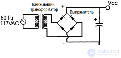
Fig. 3.8. Mains transformer and rectifier unit
Diagram of the charger is shown in Fig. 3.9.It includes an LM317 voltage regulator and a current limiting resistor. The resistance value of the limiting resistor depends on the current required to charge the battery.
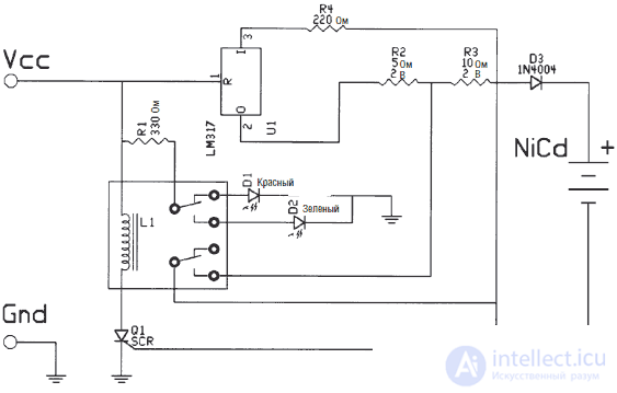
Fig. 3.9. Charger circuit
Большинство производителей NiCd аккумуляторов рекомендуют заряжать их током, равным 1/10 от их емкости, что обозначается C/10. Таким образом, батарея размера АА емкостью 0,85 Ач необходимо заряжать током C/10 или 85 мА в течение 14 часов. После полной зарядки батареи производители рекомендуют снизить ток до уровня порядка C/30 (1/30 емкости батареи) для поддержания батареи в полностью заряженном состоянии без риска перезаряда или иных повреждений.
В нашем случае рассчитаем характеристики ЗУ для зарядки аккумулятора, состоящего из 4 последовательно соединенных элементов С-типа. Емкость каждого элемента составляет 2000 мАч. Таким образом, ток C/10 составит 200 мА. Стандартное напряжение каждого элемента составляет приблизительно 1,3 В, следовательно, напряжение батареи 4 х 1,3 = 5,2 В. Следовательно, можно использовать 6-вольтовый трансформатор, поддерживающий ток не менее 200 мА.
Для расчета сопротивления ограничивающего ток резистора используется формула:
R=1,25/Icc
Где Icc необходимый ток. Подставляя в формулу 200 мА (0,2 А) получаем:
1,25/0,2=6,25 Ом
Таким образом, сопротивление ограничительного резистора должно быть порядка 6,25 Ом. На схеме (рис. 3.9) этот резистор обозначен R2. Заметим, что на схеме резистор R2 имеет номинал 5 Ом. Это ближайший стандартный номинал резистора по отношению к рассчитанному.
C/30 резисторЧтобы уменьшить силу тока до значения C/30, мы последовательно включаем еще один резистор, номинал которого составляет 2R или около 12,5 Ом. На схеме этот резистор обозначен как R3. Также подбирается резистор ближайшего стандартного номинала. В нашем случае его значение равно 10 Ом.
Принцип работы ЗУВ ЗУ в качестве источника постоянного тока используется регулятор напряжения LM317. Ограничительный резистор для значения тока C/10 обозначен на схеме R2 (см. рис. 3.9). Значение R2 равно 5 Ом в сравнении с расчетным значением 6,25 Ом. Использование стандартного резистора близкого номинала не нарушит правильную работу ЗУ. Резистор для значения тока C/30 обозначен как R3. Стандартный номинал этого резистора также близок к расчетному и не нарушает нормальной работы ЗУ. Позже вы увидите, что ЗУ способно осуществлять и «быструю» зарядку аккумуляторов, поскольку имеет устройство контроля выходного потенциала.
V1 представляет собой переменный резистор номиналом 5 кОм. Он предназначен для отпирания тиристора после полной зарядки NiCd батареи. Тиристор в свою очередь переключает двухпозиционное реле, имеющее две группы контактов.
When voltage is applied to the circuit, the current flows through the LM317 regulator, charging the battery with current of the order of C / 10. The resistor R3 is shorted by one of the relay contact groups. The current also flows through a resistor R1, limiting the current of the LEDs D1 and D2. After turning on the power, the red LED D1 lights up, which indicates that charging is in progress.
During charging, the voltage on potentiometer V1 increases. After 14 hours the voltage is sufficient to unlock the thyristor. Through an open thyristor, the voltage is applied to the winding of a two-position relay. The relay turns on, the red LED goes out and the green LED lights up. A green LED indicates that the battery is fully charged. Another group of contacts of the relay opens the short-circuited resistor R3. The inclusion of a resistor R3 reduces the charging current to the order of C / 30. Diode D3 blocks the flow of current from the battery to the memory circuit.
Determination of the trigger voltage V1Для нормальной работы схемы необходимо, чтобы тиристор отпирался только после полной зарядки NiCd батареи. Наиболее просто это сделать следующим образом: вставить полностью разряженную батарею в ЗУ, заряжать ее в течение 14 часов, а потом подрегулировать V1. После завершения процесса зарядки медленно поворачивать движок потенциометра V1 до срабатывания реле. При этом должен зажечься светодиод зеленого цвета.
Особенности конструкцииПри самостоятельном конструировании ЗУ обратите внимание на следующее. Наиболее критичным является подбор ограничительных резисторов для значений тока C/10 и C/30. Для расчета их номиналов воспользуйтесь приведенными формулами. Рассеиваемая мощность этих резисторов порядка 2 Вт.
Если зарядный ток достаточно велик (более 250 мА), то для отвода тепла снабдите схему LM317 радиатором. Если ЗУ включить до соединения с батареей, то моментально сработает реле, включится зеленый светодиод и зарядный ток окажется равным C/30.
Если ЗУ будет использоваться при более высоких значениях напряжений – пропорционально увеличьте сопротивление R1, ограничивающее ток, протекающий через светодиоды. Например, для напряжения 12 В сопротивление R1 будет равно 680 Ом, для напряжения 24 В – 1,2 кОм соответственно.
При больших значениях напряжения может потребоваться резистор, ограничивающий ток обмотки реле. Полезно измерить реальные значения тока C/10 и C/30, протекающего через заряжаемую батарею, что позволит судить о правильности работы устройства.
Последовательное и параллельное соединениеСпособ соединения элементов в батарею определяет необходимые характеристики трансформатора по напряжению и току. Если батарея состоит из 8 элементов типа С, соединенных параллельно, то необходимо умножить необходимый для каждого элемента ток на 8. Если емкость отдельного элемента составляет 1200 мАч, то зарядный ток C/10 будет равен 120 мА. Для 8 параллельных элементов ток составит около 1 А (8х 120 мА=960 мА=0,96 А). Необходимое напряжение составит 1,5 В. Соответственно, необходим трансформатор, выдающий напряжение 1,5 В при токе 1 А. Если эти элементы соединены последовательно, то необходимое напряжение составит 12 В при токе 120 мА.
Быстрое ЗУМногие современные NiCd аккумуляторные батареи можно заряжать быстрее при условии, что после их полной зарядки ЗУ переключится в режим C/30. Типичным является удвоение зарядного тока при сокращении времени зарядки в два раза. Таким образом, можно заряжать батарею током C/5 в течение 7 часов.
Хотя я не пробовал использовать данную схему ЗУ для быстрой зарядки, но не вижу оснований, почему она не должна работать. Если вы хотите это сделать, необходимо сперва подстроить потенциометр под значение тока C/10, а потом уменьшить номинал резистора R2 в два раза.
Список деталей• U1 регулятор напряжения LM317
• L1 двухпозиционное реле с двумя группами контактов
• D1 красный светодиод
• D2 зеленый светодиод
• D2 диод 1N4004
• Q1 тиристор
• V1 подстроечный резистор 5 кОм
• R1 резистор 330 Ом 0,25 Вт
• R2 резистор 5 Ом 2 Вт
• R3 резистор 10 Ом 2 Вт
• R4 резистор 220 Ом 0,25 Вт
• Понижающий трансформатор
ЗУ с питанием от солнечных батарей
Изготовив ЗУ для аккумуляторных батарей, вы можете превратить его в устройство, питающееся от солнечных батарей. Для этого достаточно заменить трансформатор и выпрямительное устройство комбинацией фотоэлектрических элементов, имеющих аналогичные характеристики по току и напряжению. При создании системы с питанием от солнечных батарей необходимо учитывать:
– средний уровень освещенности панели солнечных батарей;
– отношение времени освещения солнечных батарей, необходимого для процесса зарядки ко времени рабочего цикла.
Топливные элементы-батареи с топливным баком
Топливные элементы, как и гальванические батареи, являются электрохимическими устройствами, преобразующими энергию химических реакций в электричество. В гальванических батареях химические реагенты помещены внутрь их. Когда химические реакции прекращаются из-за истощения батареи, она подлежит замене (или в некоторых случаях перезарядке). Топливные элементы используют химические реагенты (топливо), хранящиеся вне элемента. До тех пор пока в топливный элемент поступает топливо, он будет (теоретически бесконечно) вырабатывать электрическую энергию.
Когда запас топливного элемента истощается, он легко может быть наполнен свежим топливом аналогично современным автомобилям. Робот, питающийся от топливных элементов, может быть быстро приведен в рабочее состояние в сравнении с другими роботами, требующими времени на зарядку аккумуляторов.
In fig. 3.10 shows a fuel cell design based on potassium hydroxide (KOH). This type of element is used in American spacecraft. The first thing you can notice is that the anode is marked with a (-) sign, and the cathode, respectively (+). When I first began to look at fuel cell diagrams, I thought it was a mistake, but after seeing a few dozen of such schemes, I concluded that it wasn’t really a mistake. For more confidence, I looked at the definition of a cathode in the Oxford Dictionary. It says: “Cathode. 1. The negative electrode in the electrolysis vessel. 2. Positive battery cell terminal. " I have given it only so that you will not be confused by these designations on other fuel cell circuits, since, as far as I know, such designations are generally accepted.
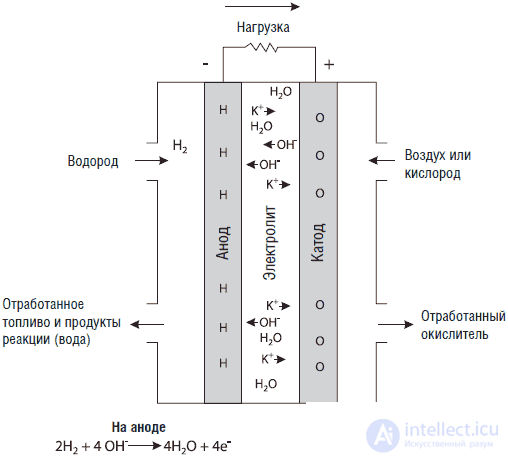
Fig. 3.10. KOH fuel cell
Fuel cells find numerous uses. Practically any devices using galvanic cells and batteries can be successfully transferred to power supply from fuel cells. In development are air / aluminum fuel cells suitable for use in cell phones, and elements for “laptop” computers. Fuel cells run longer and have improved performance.
If not now, then when?
If fuel cells have such remarkable characteristics, then where are they? Why don't we see them in our laptops, camcorders, and cell phones? Of course, the technology of production of fuel cells has greatly improved over the past decade, but in terms of costs (read - cost), it can not be compared with the production technologies of other current sources. One of the most advanced technologies uses electrodes based on proton-exchange membranes (POM) - a material called Nation, developed by the DuPont concern. The POM material itself costs approximately $ 1,000 per square meter. Cheaper production of similar membranes and the creation of other POM - materials is the primary task of creating competitive fuel cells.
Platinum is an expensive metal. The electrodes of the fuel cell are usually coated or anodized with platinum. The platinum coating is a catalyst that facilitates chemical reactions inside the fuel cell.
The development of fuel cell production technologies is also observed in the automotive industry. All leading automotive companies are engaged in ongoing research on the development and implementation of fuel cell technology. The list of companies engaged in such research resembles who-who ratings in scientific research.
The entry of fuel cell vehicles into the market is expected by 2003. Canadian company Ballard Power Systems, a major player in the POM technology market, is launching a series of fuel cell buses. In the production of fuel cells, Ballard has teamed up with such well-known companies as DaimlerChrysler and Ford Motor. Ballard recently commissioned an enterprise designed to produce 160,000 commercial fuel cells annually.
Honda plans to move to producing fuel cell vehicles already in 2007. It will use existing models of cars with electric engines designed to be powered by batteries, and will replace them with fuel cells.
Continuing research in the field of fuel cell technology is met with enthusiasm and is widely supported. Before leaving the presidency, President Clinton together with Congress allocated $ 100,000,000 to continue research in the field of fuel cell technology for the fiscal year 2001.
When fuel cells become an integral part of our everyday life, like video cameras, cell phones and laptop computers, we can use them to power our robots.

Comments
To leave a comment
Robotics
Terms: Robotics