Lecture
In this chapter we will build a robot - a tele-tracking system. As already shown in Ch. 2, such robots are widely used in science, business, entertainment, military, various kinds of research and industry.
Why are they so called
A modern science fiction writer Robert Heinlein is considered to be the first to predict the possibility of using robots - teletracking systems in a science fiction novel of 1940 called Valdo. In this novel, the person controls the mechanical dolls called "Valdo", giving commands from a remote place.
I found that instead of using the term "Valdo" the word "Golem", taken from Jewish mythology, is more appropriate for such devices. The history of the Golem describes the human spirit, which is intentionally infused into a clay figurine. The spirit controls the clay figurine, giving it orders that the spirit could not or would not like to perform in its “human” form. Once the work of the Golem is completed, the spirit returns to its human body. Such a definition very accurately describes the new science of tele-tracking. For this reason, I called my robot - the Golem I. tele-tracking system.
What is telecommuting?
The tele-tracking system is a high-precision remote control system that attempts to transfer human control actions to a remote robot. The feedback interface builds a tele-tracking system in the image of virtual reality. In fig. 9.1 shows the main units of the tracking system.
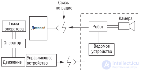
Fig. 9.1. Basic diagram of the tracking system
In virtual reality systems, we achieve immersion in a synthetic, computer-generated reality, using the illusion of “deception” of feelings, which leads to the organization of interaction with this synthesized reality and belief in its “existence”. In the tele-tracking system, the world around us is real, but is at a certain distance. Thus, instead of a computer-generated artificial reality, sensory devices mounted on a remote robot provide the operator with the necessary information about the surrounding spatial environment, as if he or she were directly in that place.
On the operator's side, as already mentioned, there is equipment such as virtual reality, which provides the display of sufficient information from remote sensory devices so that the operator's feelings “believe” that the given environment is real and present “here”. The achieved level of "presence" depends on the accuracy and accuracy of the information transmitted through the interfaces. A humanoid robot that can accurately follow human movements, gestures, movements, maintain balance and at the same time has the ability to transmit to the operator the visual, thermal, tactile and muscular sensations arising in its artificial "skeleton" will be the perfect Golem. In this case, an illusion of merging or complete immersion of the human operator into the structure of the robot should arise.
Existing tele-tracking systems solve much more modest tasks. In many cases, such a robot is a vehicle like the one we are going to build. The best examples of such devices allow to achieve the illusion that he or she controls the movement of the wagon inside it.
Such robots can be created for research or work in harsh or unhealthy conditions. The list of such conditions may include the waters of the Arctic, the ocean floor, forest fires, active volcanoes, nuclear reactors, the surface of the moon, Mars, etc.
System substructure
We will design our robot based on the model of a radio-controlled car. In the ideal case, the model should have a proportional control system for the course and turns of the car. In our prototype is used exactly this car model. Cheaper models can be used, but they provide worse quality control.
In fig. 9.2 shows a photograph of a radio-controlled car equipped with a spring suspension system. To provide a “feel” for the surface, the system can be equipped with tilt sensors and road irregularities (shaking). In this case, we are running a little ahead.
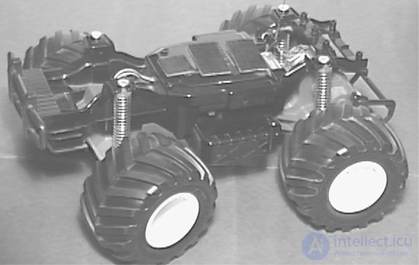
Fig. 9.2. Model of a radio-controlled car used in the tele-tracking system
Purchase a model of a car that runs on batteries and has a charger. For some models of radio-controlled cars, these devices can be purchased separately.
Some words about radio controlled cars
Radio-controlled models have become a popular hobby. There are radio-controlled models of airplanes, helicopters, gliders, boats, submarines, cars, motorcycles, etc. The frames and spring suspension systems of most models are suitable for creating Golems of robots on their base.
Until recently, most models worked on liquid fuel. In the late 70s, the development of electric battery and engine production technology made electric-powered models more popular.
Radio-controlled car models typically use two-channel receiver / transmitter control systems. On one channel, the steering is controlled, and on the other, the accelerator “pedal”. Each transmitter signal is controlled by a variable resistor on the transmitter panel. The potentiometer, which controls the rotation of the model, is often connected with a small steering wheel on the transmitter housing. The accelerator potentiometer is often connected to the handle or joystick.
The transmitter encoder chip modulates the carrier with variable width pulses. The width of the pulses depends on the position (resistance) of the variable resistor slider. The width of the modulating pulses varies from 1 to 2 ms (see Fig. 9.3). In the middle position of the slider, the pulse width is 1.5 ms. In one extreme position, the pulse width reaches 2 ms. In the other extreme position, the pulses are reduced to 1 ms.
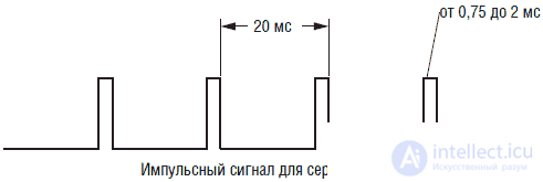
Fig. 9.3. PWM pulse train for servo motor control
The receiver decoder processes the pulses and sends the appropriate commands to the control servomotors. A servomotor is an integral structure consisting of an engine, a gearbox, an output shaft and a control circuit board. The control circuit of the printed circuit board inside the servomotor generates the corresponding pulses based on the resistance of the internal potentiometer connected to the output shaft of the servomotor. The control IC compares the pulses of the internal circuit of the servomotor and the pulses coming from the receiver decoder. By rotating the axis of the servo motor shaft, the duration of these pulses is equalized. Thus, the servomotor changes and tracks the position of the rotor shaft in accordance with the signal of the transmitter.
Eyes
An eye (or eyes) for our telepresence robot is a miniature color video camera with a soundtrack channel (see. Fig. 9.4). The camcorder kit includes a 2.4 GHz receiver and transmitter. The price of such a system is approximately $ 99.95.
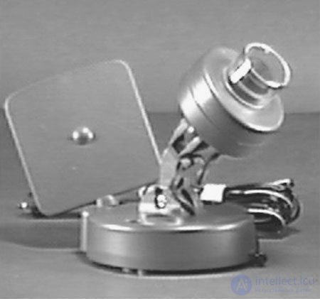
Fig. 9.4. Color video camera with sound and 2.4 GHz transmitter
The size of the camera itself is small. It is attached to the body of the transmitter using a small corner bracket. The camcorder's dimensions are quite small, so it is possible to install a set of two cameras at a distance of approximately 63 mm between the lenses (this corresponds to the average distance between the eyes) on the sides of the robot. Installing a pair of such cameras will allow the operator to get more realistic stereo images. In the prototype device, we use only one camera; Later we will discuss the possibility of improving the design with the addition of “stereo vision”, which will allow us to improve the “presence” effect and control the device through the perception of the depth of space.
The original model of our device contains one miniature video camera with sound. The design is assembled according to the modular principle, so if the reader then wants to introduce the stereotype of “view”, he can use the already available video equipment.
Design
The construction of the robot begins with the search for a suitable chassis from a radio-controlled car. Most models of radio-controlled cars have an external decorative case, which gives them the appearance of a real car, truck, all-terrain vehicle, etc. Remove the external decorative case and attach the necessary parts directly to the chassis.
The miniature color camera of the robot Golem I requires a separate power source (see fig. 9.5). For a 6 V battery, a separate battery compartment, powering video camera and transmitter are manufactured. The energy of fresh AA elements should be about 4-6 hours of continuous work.
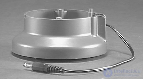
Fig. 9.5. 6 V battery compartment for four AA elements
To facilitate the installation and preservation of the modular principle, we will widely use Velcro self-adhesive tape ("sticky tape"). Velcro material is usually commercially available in the form of strips of a multiple of 30 cm. Velcro tape has the appearance of two strips fastened together. Each strip has an adhesive layer on the back. One of the bands is attached to the appropriate place of the chassis, and the other to the part that needs to be attached.
2.4 GHz video system
The 2.4 GHz transmitter is an integral part of a color video camera (see fig. 9.6). The 2.4 GHz receiver is a separate unit. The receiver unit has two RCA type connectors for video and audio output. These connectors are connected using RCA cables to the inputs of a TV, monitor, or VCR.
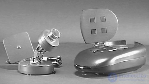
Fig. 9.6. Camera system, transmitter and receiver
The camcorder can be installed on the chassis in two ways. In fig. Figure 9.7 shows the video camera and transmitter attached to the battery compartment. You can start with a fixed position of the camera or the video camera can be mounted on the servomotor cover to ensure its rotation and tracking. It is clear that the installation of the servomotor is more complicated and requires a separate radio control channel for panning the camera left and right. In devices with the highest reliability of information transmission, camera panning should be associated with tracking the rotation of the operator’s head. Thus, if the operator turns his head to the right or left, the camera of the mobile robot pans to the right or left synchronously with the movements of the head. For the correct operation of such a system, the operator needs a special helmet-display of virtual reality, which is a very difficult task. I would advise for simplicity of construction, first use a fixed video camera.
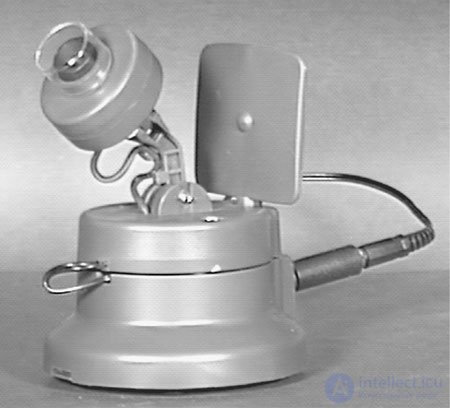
Fig. 9.7. Color video camera and battery compartment assembly, ready to be placed on a car model
For a fixed mount, you will need a small strip of Velcro glued to the bottom of the camcorder's battery compartment. The other strip is respectively attached to the chassis of the radio-controlled car. The construction of the Golem robot assembly is shown in Fig. 9.8.
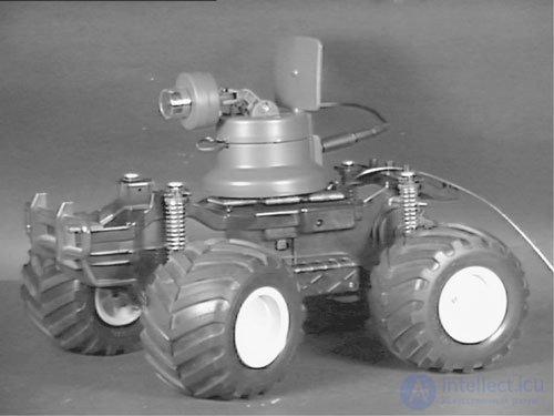
Fig. 9.8. Color video camera mounted on the car model
Control through the teletracking system
You can control the car remotely using a radio control system, and at the same time look at the screen of a television monitor. The camcorder is equipped with a microphone, so in the process of management you can hear the surrounding sounds.
Conversation
You can purchase a pair of inexpensive portable radio stations for kids like walkie-talkie. By placing one of the stations on the robot's chassis, you can talk "from the board" of the robot.
Realistic control system
In the work of Golem I used the standard radio control system that is included in the model car. Realistic tele-tracking can be significantly increased by introducing realistic-looking controls. It is easy to do. Remove the control resistors from the transmitter body and connect one of them with an improvised steering wheel, and the other with the accelerator pedal.
Improving the tracking system
With some thought, the basic model of the Golem I video tracking system can be significantly improved. It is clear that the improvements will lead to some appreciation of the device. Nevertheless, such subsystem improvements can be made gradually.
Stereo vision
It is worth trying to equip the robot Golem I with a high-definition color “view”. This attempt gives the system many additional benefits, in particular the perception of the depth of space. This is an area where it is still possible to make a significant contribution. Before embarking on the project, it is necessary to clearly understand that to view stereo images from the "board" of the robot, a special system is needed to provide such a viewing mode.
The small size of miniature stereo cameras is very suitable for stereo image synthesis. Such cameras can be placed in one row at a distance corresponding to the average distance between human eyes. For greater certainty, the average distance between the eyes in an adult is approximately 63 mm. To perceive the depth of space, camera lenses can be located at the same distance from the center to the center to simulate a person's eyes. The transmitters of both cameras must be tuned to different frequencies. This will allow a special television display to transmit the left image to the left eye, and the right image to the right eye.
The stereo images received from the Golem board will allow the operator to perceive the depth of space at the time when he or she controls the device. Stereo vision becomes much more important when it is necessary to perceive the depth of space, for example, when using an artificial robot arm. The ability to visually control the position of the manipulator (robot arm) along the Z axis in three-dimensional space (X, Y, and Z axes) greatly increases the efficiency of control.
It is rather difficult for the operator to control the manipulators (by the hands of the robot) effectively in the absence of Z-depth measurement in monocular vision. In this case, the operator is forced to slightly push objects with the manipulator in order to accurately determine the position of the manipulator arm along the Z axis.
The same thing happens when the car is remotely controlled via the TV tracking system. With the loss of perception of depth it becomes difficult to determine the distance to objects in front of the car.
After installing the stereo system, the operator will see a three-dimensional image of the space in front of the car. However, this transmitted stereo image will lack very important information corresponding to convergent eye movements. We obtain information about the distance to an object largely due to the convergence (convergence) of the eyes. Convergence is the convergence of the optical axes of the eyes when they are rotated inside the eye orbits when viewing an object. When looking at very close objects, the eyes must be turned "inward." On the contrary, when viewing very distant objects the direction of the axes of the eyes will be almost parallel. The brain automatically takes these movements into account when calculating the distance to the object.
Stereo video cameras are in a fixed position and directed straight ahead. To add the possibility of "convergence" of cameras, you need devices that track the position of the eyes. A stereo image display device should be provided with a feedback unit that continuously monitors the position of the operator’s eyes. The obtained information should be transmitted to the servomotors on which the video cameras are installed in order to bring the optical axes of these video cameras closer in proportion to the convergence of the operator’s eyes.
Such a master-slave system, as far as I know, has not yet been created. The accuracy of its performance probably depends on how much such a system can assist the operator in determining distances. Creating such a system is beyond the scope of this book, however, it can be on the shoulder of an experienced and persistent experimenter.
Digital compass
In ch. 5 describes digital compass diagrams that may be useful in the construction of the Golem robot. The compass can be installed in two different ways. In the first method, the indicator LEDs of the compass are placed in the field of view of the video camera. Quickly looking at the indicators, the operator receives information about the direction of movement of the robot. The second method requires data transmission from the digital output of the compass to the operator via a radio channel.
Interface sensor surface irregularities
При управлении автомобилем через систему телеслежения вы не можете чувствовать наклона или неровностей дороги, по которой движется автомобиль. Для введения «чувства» неровностей дороги в систему вы можете использовать систему пружинной подвески модели. Для этой цели подойдут многие типы датчиков: например, пьезоэлектрические преобразователи, датчики Холла, индикаторы деформации и т. д.
Вызовом экспериментатору является не просто обнаружение неровностей, но отображение этой информации через сидение оператора. Большинство подобных платформ используют дорогие пневматические и гидравлические системы привода. Если цена слишком высока, то этот выбор исключен.
Cheaper solutions are ThunderSeat seats manufactured by Thunder Seat Technologies. ThunderSeat uses any sound source to generate vibrational vibrations. It uses a subwoofer loudspeaker connected to a sound chamber inside the seat. The sound chamber transmits vibrations throughout the seat. Subwoofer (subwoofer) develops power up to 100 watts. The frequency range of the system from 50 Hz to 3.7 kHz. Originally, the system was created for an airplane flight emulator controlled by a sound card of a personal computer. The output of the sound card was connected to an amplifier, to which, in turn, ThunderSeat was connected.
Tilt Sensor Interface
Точно так же, как для интерфейса датчиков неровностей поверхности, можно использовать различные датчики-преобразователи для определения наклона (см. гл. 5). В одном из датчиков используется стальной шарик в пластиковой оболочке. При наклоне шарик замыкает электроды, закрепленные в оболочке. Для этой цели могут быть использованы ртутные выключатели.
Наилучшими, но самыми дорогими датчиками являются датчики электролитического типа. Один такой датчик способен выдавать информацию по двум осям наклона. Герметически запаянный датчик имеет один центральный электрод, окруженный четырьмя равноотстоящими электродами. Залитый электролит обеспечивает электрический контакт между электродами, причем сопротивление этого контакта по переменному току пропорционально углу наклона.
К сожалению, электролитические датчики не могут работать в цепях постоянного тока. Постоянный ток вызывает осаждение компонентов электролита на электродах, что приводит к его порче. Чтобы избежать этого, датчик запитывается переменным током частотой 1000 Гц и напряжением 3 В. Напряжение переменного тока на центральном электроде пропорционально наклону датчика.
Если вы все же решите использовать подобный датчик, то я могу предложить вам один способ съема данных информационного потока. Для этого необходимо соединить выход датчика по переменному току с мостовой выпрямительной схемой для получения напряжения постоянного тока. Это напряжение можно подать на ГУН (генератор, управляемый напряжением). Частота ГУН зависит от амплитуды управляющего напряжения. Информация с ГУН передается по радиоканалу на приемное устройство, которое управляет платформой сиденья оператора. Приемник декодирует сигнал (наклон) и осуществляет пропорциональное управление наклоном платформы.
Фирма Spectron Inc. выпускает ИС типа SA40011, которая обеспечивает простой интерфейс электролитического датчика наклона. Сигнал постоянного тока с выхода ИС SA40011 может управлять ГУН, как это было описано выше.
Как и в предыдущем случае, устройство наклона операторского места является одной из самых сложных частей системы. Для наклона сиденья можно использовать пропорционально управляемые пневматические или гидравлические системы.
Увеличение радиуса действия видеосистемы
Радиус действия нашего небольшого передатчика лежит в пределах от V 30 до 100 м. Для увеличения радиуса действия необходимо применение другой системы – она называется любительским телевидением.
Любительское телевидение существует уже в течение ряда лет. Это способ, используемый радиолюбителями для двухстороннего обмена изображениями. До недавнего времени цена оборудования была достаточно высока, поэтому такое могли позволить себе только отдельные «элитные» радиолюбители. С развитием твердотельной технологии ситуация изменилась.
Все компоненты для системы любительского телевидения мощностью 5 Вт можно приобрести за $200, исключая телевизионный монитор и видеокамеру. Для любительского телевидения подойдут камеры, используемые в роботе Голем I. Менее мощные системы любительского телевидения (0,75 Вт) можно приобрести за $100.
Для легального использования подобных систем на территории США необходима радиолюбительская лицензия Technical class. В настоящее время для получения данной лицензии знание азбуки Морзе необязательно. За дополнительной информацией можно обратиться в местный радиолюбительский клуб. Можно отправить письмо в American Radio Relay League (ARRL), 225 Main Street, Newington, CT 06111, или позвонить (800) 594-0200 или (203) 666-1541 (факс: (800) 594-0259).
Пятиваттная система любительского телевидения может обеспечить связь на расстояния до 50–70 километров в соответствии с уровнем местных помех, рельефа, погоды и т. д.
Other models
Полученный при конструировании системы телеслежения опыт поможет читателю в создании других моделей. Компания, производящая Erector Sets, постоянно совершенствует и обновляет ассортимент интересных конструкторских наборов, выпускаемых на рынок. Эти наборы, которые называются Meccano-Erector Sets, содержат двигатели, редукторы, шкивы и прочие стандартные детали Electro Set.
Выпускаются стандартные наборы для изготовления самоходных платформ, автомобилей, мотоциклов, вездеходов и пр. В этих наборах имеются очень хорошие платформы на пружинной подвеске, пригодные для изготовления экзотических моделей роботов. Наборы можно приобрести у местных US-дилеров Toys R.
The list of details of the robot - tracking devices
• (1) Miniature color video camera with 2.4 GHz receiver and transmitter
• (1) Extra battery compartment
• (1) Proportional radio control system (receiver / transmitter - two channels, quartz resonators, servomotor with a torque of 1.3 kgf)
• (1) Velcro adhesive tape 30 cm

Comments
To leave a comment
Robotics
Terms: Robotics