Lecture
Aerobots are a class of robots that can fly. This includes vehicles lighter than air (airships), helicopters and airplanes. Such devices are used in autonomous and unmanned flights, military affairs, aerial surveillance, entertainment and tele-tracking systems.
Unmanned aircraft has a fairly long history: the first vehicles appeared in the early 20s. One of these unmanned aerial vehicles had the codename “bug” and was intended for military purposes. The length of the "beetle" was 3.6 meters, and the wingspan - 4.5 meters. His navigation system was quite advanced for that time and included a gyroscope, altimeter, and pneumatic and electrical control systems. The flight control system sent the device 50–70 km deep into enemy territory. When the plane reached a predetermined region, the apparatus dropped its wings, and the heavy fuselage was dropped on the ground, carrying a 200-pound charge of explosives. However, the device did not find massive use in connection with the end of the 1st World War.
From the very beginning, the design of such unmanned vehicles were subject to constant improvements and modifications. The latest models of unmanned aircraft were used in the Gulf War. This action almost did not find reflection in the press, although more than 300 sorties were flown. These devices were used in reconnaissance to assess the losses of the enemy and the detection of weapons depots. The most famous and perfect unmanned aerial vehicles can be called self-guided intercontinental missiles with nuclear warheads.
Remote control systems and "presence" on aircraft also have a fairly long history, though not as long as unmanned aerial vehicles. The United States used in the 2nd World War, remotely operated aircraft for flight "kamikaze." The control systems of that time, of course, cannot be compared with modern advanced devices. These systems were not sufficient and reliable, and in order to accurately pilot the device, the pilot had to visually observe the flight.
Today, remotely controlled aircraft have video cameras that transmit the image to the pilot operator. The pilot can be anywhere in the world. Such systems today have become a tele-tracking system based on the principles of virtual reality.
We will manufacture an airborne - airship with a tele-tracking system. I decided to make the device lighter than air, because in comparison with the model of an airplane or a helicopter it is safer, produces no noise, is cheap and easy to manufacture.
Airships fly quietly, slowly, gracefully and "forgive" piloting errors. The main reason for my decision was security. If the airship collides with the object or person, it will not be able to cause him any harm. On the other hand, a plane or a helicopter can be dangerous to a person (the rotating propeller of an airplane or helicopter may accidentally become a deadly weapon) when the flight takes place in close proximity to people.
We will make a model of a small airship with a soft shell (hereinafter, simply “airship” - a comment of a translator), intended for flights inside the premises. It is necessary to carefully consider the selection of parts of the structure, which should be of extremely low weight. Airship lift capacity is about 6 ounces. This means that the radio receiver, propulsion device, power source, CCD video camera and video transmitter must have a weight not exceeding 185 grams. The restriction is very strict, but doable.
Types of aircraft lighter than air
Aircraft lighter than air consists of three categories: rigid, semi-rigid and non-rigid (with a soft shell). The shell of a rigid aircraft is usually made of lightweight aluminum. The most famous are cepellins.
Semi-rigid devices have a rigid cabin located in the keel part of the device. A soft shell filled with helium is mounted on top.
The most famous today are devices of non-rigid (soft) type. These are the airship balls. The most famous are Goodyear balls used for promotional purposes. Such a balloon-airship is a soft shell that takes shape when filled with helium.
Airship Systems
Most often, airships are used today to observe the progress of football matches from a bird's-eye view. Also balloons - airships are used for promotional purposes.
The technology of such devices may seem outdated, but scientists and engineers are finding new applications for them. For example, the US Army uses the SASS LITE (mini-tracking and detection of single objects), which is used to patrol borders. Recently, the manufacturer announced that the 90-foot aircraft can also be used for commercial purposes.
Helium filled balloons are able to reach the upper stratosphere. One of the companies proposed to create a flying air station at an altitude of more than 30 km above the Earth. By analogy with the satellite, a telecommunication link will be carried out with a similar station. At the same time, the cost of such a station will be 50% of the cost of a satellite equipped with similar equipment.
Robotic and tele-tracking systems have been installed on airship models for a number of years. We will briefly talk about two projects, one from The Robot Group and the other from Berkley's WEB Blimp. Then we will focus in detail on the installation of a simple tracking system on the model of the airship. In reality, the tracking system is a portable, lightweight wireless video surveillance system. Sensory feedback systems, such as touch sensors that mimic the sense of touch that are necessary for a “real” tele-tracking system, have not been developed. Our simple system transmits image and sound. The user or operator can control the flight of the airship through the radio control system.
The Robot Group - Austin, TX
A robotic system was installed on the model of the airship. The Robot Group from Austin, Texas, demonstrated the airship robot at the first Robofest festival in the autumn of 1989. I am sure that the robotic systems installed on airships were used previously for military or scientific purposes, but The Robot Group presented private (non-government funded) research in this area. The Robot Group continues to develop and improve robotic airships. In 1991, the Mark III computerized airship project was introduced using ultrasonic sensors and neural networks as a navigation system. Although the system in general has not met the expectations of developers, its operation can be considered quite satisfactory.
The Robot Group has a website on the Internet that you can visit and get the latest information (email address at the end of the chapter).
WEB Blimp - University of Berkeley, California
Space "collector" - this name was given to the tele-tracking system, placed on the airship, which was developed and manufactured at the University of Berkeley, California, at the Faculty of Radio Electronics and Computational Mathematics. These airships can be represented as “avatars”, or “celestials”, or, as I prefer to call them, “golems”.
A group from Berkeley has made efforts to create a system of bodily "reincarnation." This system of physical "transformation" requires a complex system of sensory feedback from the airship "avatar" to the operator. Currently, the feedback system includes the transmission of sound and images, and the user can control the airship by radio.
The most interesting in the design of this airship is that it can be controlled via the Internet (hence its name - WEB Blimb, i.e. WEB airship). The video image is transmitted to the network via a video card of the CU-SeeMe format. WEB airship is available online via the Berkeley website (see access address at the end of the chapter).
Creation of airships of tele-tracking systems in the form of "avatars" and "golems"
Well, where we do not! Robotic airships or similar structures have a great future in the industry of remote surveillance and tele-tracking. Imagine that you want to see a few pictures in the Paris Louvre, visit the American Museum of Natural History in New York, then go to the Smithsonian Institution in Washington and finally watch the penguins in the Galapagos Islands. And we agree that the entire journey should take a couple of hours.
One of the ways to do this in real time is to use the tracking system. Sometime in the future, tele-robots equipped with “vision” will appear, which will be able to communicate via a telephone (or satellite) channel with your home virtual reality system. These robots will be located in many interesting places around the globe.
Telerobots will not only be tied to Earth. Robots that are in space, under water, or flying in the air will be created. Jason's project involves the creation of an underwater system of scientific and educational "adventures" for schoolchildren. Through the telecommunications system, schoolchildren will be able to contact scientists located on a distant ship. Students will be able to learn about what scientists are doing, ask questions and sometimes fly a TROV (vehicle equipped with a tele-tracking system) using a telecommunications system.
Journey to the moon
The Lunacorp Company in Fairfax, Va., Plans to launch a civilian all-terrain vehicle on the Moon (see Figure 14.1). For some part of the time, this all-terrain vehicle will be used as a tele-tracking system controlled from the Earth (see. Fig. 14.2). Unfortunately, the price of such “driving” is high and amounts to approximately $ 7,000 per hour. I do not know about you, but I would donate $ 120 to ride an all-terrain vehicle on the lunar surface for a minute.
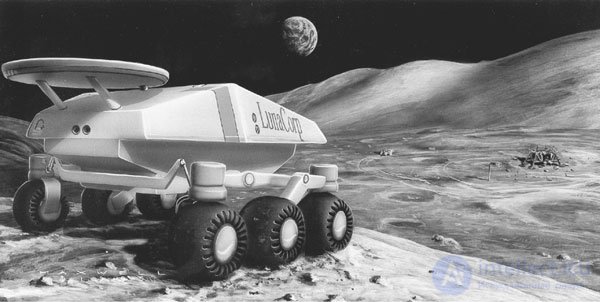
Fig. 14.1 Lunacorp ATV
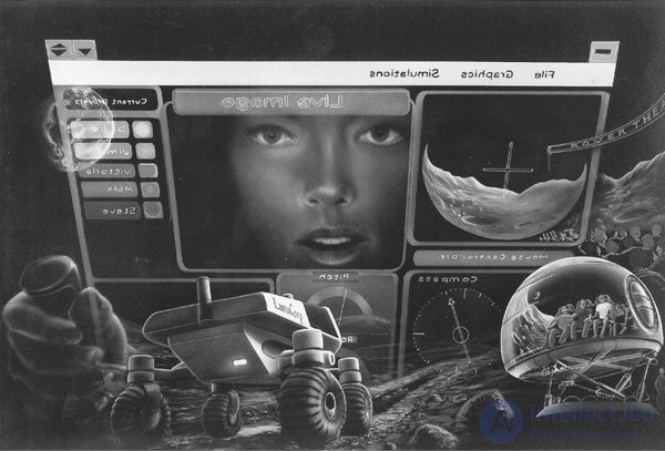
Fig. 14.2. Telecommunication system Lunacorp. Artist version
Lunacorp plans to deliver an all-terrain vehicle to the moon in the Sea of Tranquility. But we deviated from our topic of airships.
Airship Parameters
For effective use in ground-based tracking systems, airships must meet several criteria. The airship should be absolutely safe for people around. Airships should be able to move in the same directions that people use. CCD video camera should be approximately at the level of human eyes. The airship must withstand a small headwind without any difficulties.
The ballast system should allow the airship to “hang” in the zero buoyancy position on one or more floors of the building. If the creation of such a ballast system is difficult, then it is necessary to place airships with zero buoyancy on each floor. When changing floors, the operator must easily connect to an unused telepresence robot located on the required floor.
Physical limitations are imposed on airships due to their low weight. For example, the airship cannot push the door open. Buildings require renovation, in which the doors and elevators will be electronically controlled by commands from the airship.
Airship Construction Kit
We will manufacture the airship from durable Mylar type material. The material can be joined by hot welding using a domestic iron. There are many possible forms of airships: in the form of a flying sausage, in the form of a hang-glider wing, or an ordinary airship — a Goodyear-type ball. I propose the simplest design - a pillow-shaped airship.
It is very easy to make a pillow shaped airship. Bend a sheet of Mylar material in half (shiny side out). Weld its three open sides, leaving a small hole at the bottom for the gas filling nozzle, and everything is ready.
Helium
Helium is sold in bottles in many stores for "party" goods and is designed to inflate balloons. The cylinders are shaped like propane cylinders. If there is no similar store in your area, look for a supplier in the Yellow Pages.
Helium or hydrogen
When I started the project, I was thinking about using hydrogen instead of helium, for the reason that since the weight of hydrogen is almost half the size of helium, then we can expect an increase in lifting force by half. Right thought? Mistake!
My assumption that the weight of hydrogen is almost half the weight of helium turned out to be correct (see Table 14.1), but I miscalculated the lifting force, and here's why. Lift force occurs when replacing the air volume with hydrogen or helium is similar to an air bubble in water. Let's use this analogy. The density of air is less than the density of the surrounding water, so the bubble is pushed to the surface. Similarly, helium is less dense than the surrounding air, and therefore it rises. From tab. 14.1 it can be seen that raising helium or hydrogen upwards in the thickness of a denser gas, i.e. air, is determined by their lower density.
Table 14.1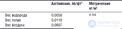
So, what is the lifting force of a helium balloon with a volume of 0.14 cubic meters?
Expelled air weight = 0.14 (1.29) = 0.18 kg
Weight 0.14 cubic meters. helium = 0.14 (0.178) = 0.025 kg
Lifting force = 0.18 kg - 0.025 kg = 0.155 kg
The lifting force is big enough! This happened because we did not deduct the weight of the ball itself. Suppose the ball weighs 0.1 kg, then the useful lifting force (0.155 kg-0.1 kg) decreases to 0.055 kg, or 55 g.
Weight 0.14 cubic meters. hydrogen = 0.14 (0.09) = 0.012 kg
Lifting force = 0.18 kg - 0.012 kg = 0.168 kg
Difference in lift for a 0.14 cubic meter ball. will be:
0.168 kg - 0.155 kg = 0.013 kg, or 13 g.
The difference in lift was very small, so do not be at risk using hydrogen. I would advise to use only helium.
Dimensions of the airship
The size of the piece of material Mylar, which is used to manufacture the airship, after bending in half, is in flat form 860x1422 mm. The weight of the material is 93 g. It is rather difficult to determine the amount of helium filling the airship. For a rough estimate, I will assume that the airship will have the shape of a cylinder. I know that the pillow does not have a cylindrical shape, but, as I said, this is a rough estimate. First we find the diameter. The piece of material has a length of 860x2, i.e. the circumference will be 1720 mm. The circumference is equal to the radius multiplied by 2p. Calculate the radius, which is equal to 280 mm. The volume of the cylinder is equal to the square of the radius multiplied by n and the height of the cylinder. The height in this case is 1422 mm. From here the volume of the cylinder will be equal to 0.32 cubic meters.
The airship will not be filled with gas to full volume. In this case, I will assume that the filling will be 70% of the calculated value, or about 0.22 cubic meters. helium.
Lift calculationExpelled air weight = 0.22 (1.29) = 0.29 kg
Weight of helium = 0.22 (0.178) = 0.04 kg
The weight of the shell made of material Mylar = 0.09 kg
Useful lifting force = + 0,29 - 0,04 - 0,09 = 0.16 kg, or 160 g.
The design of the airship
The design of the airship is simple and does not require special comments. The main problem is the reliability of the weld. For practice, cut a small strip from a sheet of Mylar material. Bend the Mylar strip with the shiny side out and the dark side inward. Put the iron adjuster in the middle position. Adjusting the temperature of the iron, iron the material to obtain the connection of the desired quality. After you change the temperature of the iron, wait five minutes to stabilize the heating. If the temperature is too high, the material will “flow” and holes will appear in it. If the temperature is too low, the welded parts can be separated too easily. With the right welding temperature, considerable effort will be required to separate the seam. Before trying the strength of the seam, cool the Mylar material for a minute. Having found the correct temperature setting, remember it for future use.
We will produce a pillow shaped airship. Bend the sheet of Mylar material in half with the shiny side out. Weld the three open sides, leaving a small hole for the choke filling the airship with gas, and you're done. The seam width should be between 12 and 25 mm.
CCD video camera
A video camera with a CCD sensor provides image transmission from the airship (see fig. 14.3). Naturally, weight is taken into account first. The camera weighs a little more than 15 g. The dimensions of the camera are 31x31x3 mm. The photosensitivity of the camera is 0.03 lux, the resolution is 430 TV lines. 1V output signal in NTSC system. The camera is powered by a constant voltage source of 9-12 V. The current consumed by the camera is approximately 100 mA.
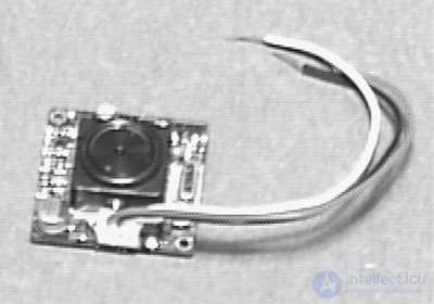
Fig. 14.3. Lightweight CCD video camera for system tracking
The camera can be powered by a 9-volt Krone battery. The battery's weight (45 g) is three times the weight of the camera itself.
TV transmitter
There are several types of TV transmitter equipment sets that are divided into two main classes. Transmitters of the first type transmit video- and audio signals at the frequency of one of the standard television channels. The television receiver receives the signal and displays it on the screen. The range of such a system is about 100 meters.
Another type of transmitter is much more expensive. They transmit signals above the frequencies of the television range (the frequency is about 900 MHz), so a special converter is required to view on the TV screen. The converter receives a signal at a frequency of 900 MHz and lowers it to the frequency of a standard television band. Such a system has a large range and the best image quality. The unit used in the initial version of the device transmits signals directly to a television receiver in the VHF band (channel 14) (see. Fig. 14.4).
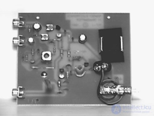
Fig. 14.4. TV transmitter board
Radio control system
The radio control system is specially designed for such airships (see Fig. 14.5). It has an extremely low weight. The propulsion unit is a twin turbofan attached to the bottom of the airship. Each fan can rotate in both directions and is controlled separately by a two-channel radio transmitter.
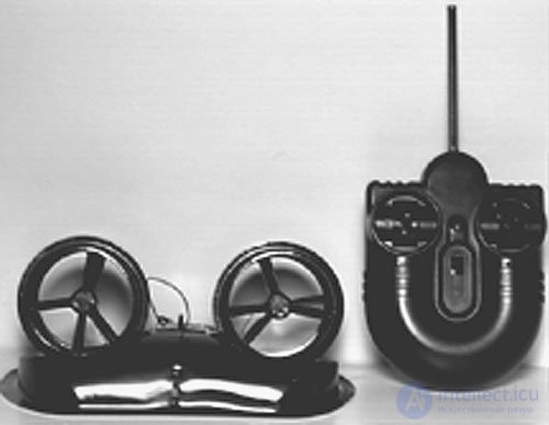
Fig. 14.5. Easy radio control system for the airship
This design allows you to increase the maneuverability of the airship. When one fan pushes the airship forward and the other backward, this allows you to quickly deploy the entire structure. The airship cushion, ready for the tele-tracking process, is shown in fig. 14.6.A detailed view of the turbofan, a miniature CCD video camera and a television transmitter is shown in fig. 14.7.
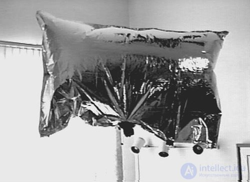
Fig. 14.6. Airship pillow
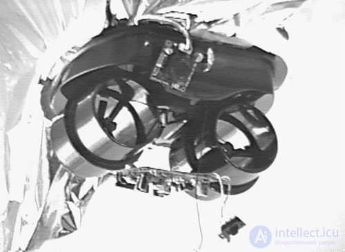
Fig.14.7. Detailed view of a turbofan, CCD video camera and transmitter
Дирижабль как он есть представляет собой систему телеслежения. Если снабдить его автономной навигационной системой, то мы превратим дирижабль в летающего робота.
Список деталей дирижабля
• (1) дирижабль с радиоуправлением, #T30824-77
Деталь можно заказать в:
Edmund Scientific
60 Pearce Ave
Tonawanda, NY 14150-6711
1-800-728-6999
• (1) Миниатюрная ч/б ПЗС видеокамера
• (1) Миниатюрный ТВ передатчик

Comments
To leave a comment
Robotics
Terms: Robotics