Lecture
The sensorics of robots (a system of sensitive sensors) usually copies the functions of human senses: sight, hearing, smell, touch, and taste. The sense of balance and position of the body in space, as a function of the inner ear, is sometimes considered a sixth sense. The functioning of biological senses is based on the principle of neural activity, while the sensitive organs of robots have an electrical nature. There may be objections that in fact both of these groups are of an electrical nature, based on the indication that the neural and electrical circuits have a common electrochemical origin. However, neural sensory functions differently than just electrical. For this reason, to eliminate discrepancies, we define the sensorics of the robot as having an electrical nature.
To fully imitate the biological organs of the senses, it is necessary to use neural sensing devices (sensors). An example of such a neural sensor is the human ear, whose work we consider. The characteristic of the human ear is non-linear. His response to a sound stimulus is logarithmic. This means that a tenfold increase in the sound level causes a twofold increase in the subjective volume level. For comparison, a conventional audio receiver, such as a microphone, has a linear output response. Hence, a tenfold increase in the level of the output signal supplied to a computer, microcontroller, or other circuit corresponds to a tenfold increase in the audio signal.
Touch sensors can detect some external signals and determine their magnitude, which results in the appearance of a proportional electrical signal at the output. The information contained in the signal must be read and processed by the “intelligence” of the robot (for example, a CPU) or a neural network. We can characterize artificial sensors according to their relation to natural sense organs, but usually the classes of sensor devices are distinguished according to the type of impact on which a given sensor reacts: light, sound, heat, etc. Types of sensors built into the robot are determined by the goals and location its application.
Signal processing
When choosing the type of sensor device used in the robot, it is necessary to solve the problem of reading and processing the signal coming from it. Vjui Many sensors are resistive-type sensors, which means that their resistance varies with the amount of incoming energy. If such a sensor is part of a voltage divider, then the amplitude of the output signal will be proportional to the amount of incoming energy.
If the robot needs a real value of the intensity of the incoming energy, it is necessary to use an analog-to-digital converter (ADC). The ADC measures the input electrical signal and outputs the corresponding binary code.
A microcontroller or digital circuit is required for proper operation and conversion of ADC data. In many cases, using an ADC is not necessary. In some cases, it is enough to use a comparator.
As the name implies, the comparator compares two electrical voltages. One of the voltages is called the reference voltage and is set according to our wishes. Other voltage is provided by a touch sensor (via a voltage divider). The output of the comparator has two levels - high and low. High level corresponds to +5 V, low level - 0 V.
The output of the comparator depends on the ratio of the voltage levels at its two inputs. Three states are possible: the sensor voltage is less than the reference voltage, equals or exceeds it.
An example of building a comparator
The best way to get acquainted with the work of the comparator is to use it in the scheme. Looking at the pic. 5.1, you will immediately find that the comparator looks almost the same as an operational amplifier. It really is; Comparators are specialized operational amplifiers (op amps). The comparator used in the first example is a quad comparator of type LM339. This integrated circuit consists of four comparators and is enclosed in a 14-pin package. Similar to OU, the comparators have inverted and non-inverted inputs. In this case, the reference voltage is applied to the inverted input (-).
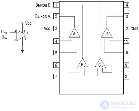
Figure 5.1. The comparator circuit and quad comparator on the IC LM 339
Voltage divider
The voltage divider is a simple but very important element of the circuit. Its use allows to connect most resistive sensor sensors with the input of the comparator. The reference voltage is also obtained using a voltage divider on two 10 kΩ resistors (see Fig. 5.2A). VoP in this case it will be equal to 2.5 V, i.e. half of the supply voltage of 5 V (see table. 5.1). It is clear that the value of VoP. may be any from zero to the supply voltage and depends on the ratio of the resistance of the voltage divider.
Vep. = Vp. XR2 / (R1 + R2)
where V pit. = 5 V.
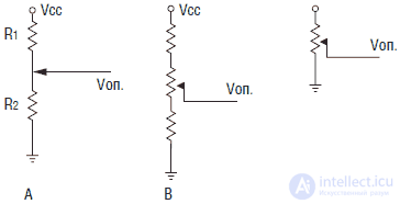
Fig. 5.2. Voltage dividers A, B and C
Table 5.1. Dual Resistor Voltage Divider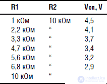
To create a variable voltage divider, you can use a variable resistor, as shown in Fig. 5.2B and 5.2C. I prefer the 5.2A scheme as the simplest.
Scheme for testing the device is shown in Fig. 5.3 Instead of a touch sensor, we will use two 1 kΩ resistors and a 5 kΩ variable resistor. Variable resistor can adjust the amount of voltage supplied to the non-inverted input. The comparator output is usually an open collector NPN transistor, the output current of which is more than enough to connect an LED, which we will use as an indicator. In other words, the output of the comparator can be used as an electronic key locked to ground. This will be useful later when switching the timer type 555.
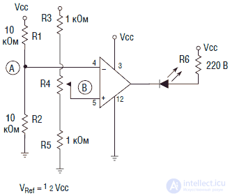
Fig. 5.3. Comparator operation check circuit
After assembling the circuit, let's see what will happen. When the input voltage is less than the reference Vop., A low level of 0 V will be present at the output of the comparator, a current will flow through the LED, causing it to glow. If we use a variable resistor to increase the voltage Vin. to a level higher than VoP. the output level will change to the “high” position, and the LED will go out. You can check the operation of the comparator with a voltmeter by measuring the voltage values on the inverted and non-inverted inputs.
Many, including myself, find the work of such a scheme somewhat unnatural. More common is the ignition of the LED when Vvc is exceeded. over VoP This can be done easily by swapping the connection points for the inputs of the comparator, that is, by connecting Vin. to the inverted input of the comparator, and VoP. non-inverted respectively. The exit function will change to the opposite.
If the scheme does not require a large number of comparators, then as a comparator you can use a CMOS operational amplifier, switched on accordingly. I prefer to use similar op amps, since they provide sufficient output current to power the LEDs and other parts of the circuit (see fig. 5.4).
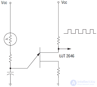
Fig. 5.4. The scheme of testing the comparator at the OS
Light sensors (photosensors)
There are many different types of light sensors: photoresistors, photoelectric devices, photodiodes, and phototransistors. Light sensors can be used to determine the position and direction of movement. Some robots use IR sources and IR receivers to bypass obstacles and prevent strikes against walls. The source and receiver of infrared radiation are mounted in front of the robot and have the same direction. When the robot approaches the obstacle or the wall, IR radiation is reflected from their surface and is detected by the IR receiver. The CPU of the robot interprets this increase in signal as an obstacle and leads the robot around it.
In front of the light sensor, filters can be installed that emit light waves of a certain length and absorb other ones. An example of such filters can serve as filters installed on fire robots and detecting the presence of an open flame. By selecting a filter, it is possible to isolate the light emitted by the flame and attenuate the light rays coming from other sources.
Another example is the use of emulsion color filters to distinguish between colors. You can imagine a robot picking up or picking only ripe fruit based on the color of their skin.
Photoresistors
Cadmium sulfide photoresistors (see fig. 5.5) are devices that react to visible light. The absorption spectrum of such a resistor is close to the spectrum of the human eye (see Fig. 5.6). The CdS photoresistor is a semiconductor, but without the usual PN junction. Such a photoresistor has the greatest resistance in complete darkness. As illumination increases, its resistance decreases. By measuring the resistance of the resistor, you can estimate the average illumination in the visible spectrum.
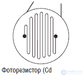
Fig. 5.5. Cadmium sulfide photocells (CdS)
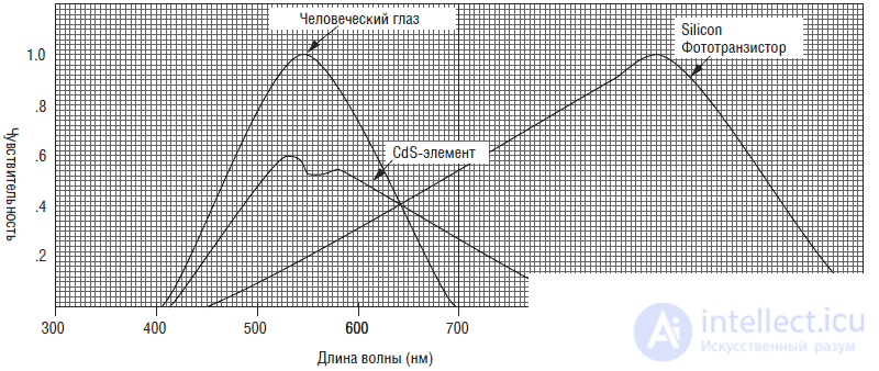
Fig. 5.6. Diagram showing the relative spectral sensitivity of the eye and photosensitive sensors
In fig. 5.7 shows the main scheme of the device. Since the CdS converter is a resistor, it can be directly connected to the voltage divider. As the illumination increases, the resistance of the photoresistor decreases. Accordingly, the voltage rises at the resistor R1 and at pin 2 of the IC. When the voltage exceeds the voltage at pin 3, the motor M will turn on. The response threshold is controlled by a 4.7 kΩ trimmer R1. This scheme is the main to control the "sun globe", described in Ch. 12.
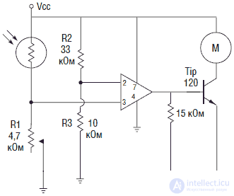
Fig. 5.7. Light switch on the photoresistor
In fig. 5.8 shows a diagram of a photosensitive neuron. As illumination increases, the frequency of output pulses increases. Such a photoneuron circuit can generate clock pulses for a stepper motor controller of the type UCN5804. With an increase in the intensity of illumination, the stepping motor turns faster.
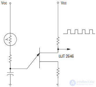
Fig. 5.8. Photoresistor based neuron
Photoelectric devices
Photoelectric (solar) elements, photodiodes and phototransistors have a similar design. They all have a photosensitive PN junction. In solar batteries, the PN junction area is large and is used to generate electrical energy in proportion to the degree of illumination.
Photodiodes are commonly used in reverse circuit designs. The luminous flux reduces the barrier of the PN junction, and current begins to flow through the diode. The response time of photodiodes is much shorter than CdS photoresistors, so they can be used to detect modulated light signals.
Phototransistors are photosensitive transistors. Their advantage over LEDs is that they are capable of amplifying the incoming light signal.
IR radiation sensors
IR radiation sensors operate in the low frequency range of light wave radiation (900 nm and below). They deserve special consideration, since they are widely used in robots for orientation, circumvention of obstacles and communication.
The use of IR sensors is not difficult. Different distributors have modules containing a modulation detector (see Figure 5.9). Their advantage is that they detect an IR signal modulated by a strictly defined carrier frequency (usually around 40 kHz).
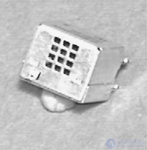
Fig. 5.9. IR receiving module
The carrier frequency of 40 kHz can be modulated in turn by another low-frequency signal. The receiving module is also made in such a way that it "receives" signals only at a carrier frequency of 40 kHz. This method allows you to create a very reliable communication channel. First, the receiving module detects a 40 kHz carrier and only then "unlocks" the device to receive the modulation signal of the IR transmitter, filtering, thus, signals from other sources. After this, a modulated signal with a carrier of 40 kHz is detected.
Infrared obstacle detectorIn fig. 5.10 shows a simple obstacle detector. As the device approaches an obstacle, the flux of reflected IR radiation increases. Accordingly, the voltage at the infrared receiver increases, which at some point throws the comparator and gives a signal informing about the presence of an obstacle in the direction of travel.
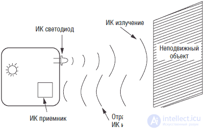
Fig. 5.10. Image of IR Obstacle Detector
In fig. 5.11 shows a diagram of the IR transmitter. The transmitter uses the IC timer type 555 in generation mode. Variable resistor R1 adjusts the frequency of the output pulses. The timer output is connected to an NPN type 2N2222 transistor, in the emitter circuit of which the IR LED is turned on. Please note that the diode will not glow when the circuit is operating, since the IR radiation is invisible to the human eye. Since we are constructing a simple obstacle detector, 40 kHz carrier modulation is not required.
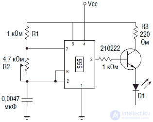
Fig. 5.11. IR transmitter circuit
Figure 5.12 shows the IR receiver circuit. The receiving module is an Everlite IRM-8420 device, having a center frequency of 37.9 kHz and a bandwidth of 3 kHz (± 1.5 kHz). The module output is a low level output. This means that when a signal is detected, the output “sits down” on the ground. Such an output is equivalent to the NPN output of an open-collector structure (see inset in Fig. 5.12). The output current is sufficient to ignite the LED. In the test circuit, the presence of a signal will cause the LED to light up.
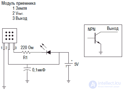
Fig. 5.12. IR receiver circuit
Position the IR transmitter and receiver next to each other in the same direction. In order for the IR LED of the transmitter to emit light in a strictly defined direction, it must be enclosed in an opaque tube. If you do not do this, the setup may not be possible. Remember that some plastics impermeable to visible light may be transparent to infrared rays.
Place a square piece of white cardboard (about 8 cm on the side) in front of the receiver and transmitter. Adjust the resistance value R1 until the LED lights up. Then remove the cardboard - the LED should go out. If this does not happen, it is possible that lateral infrared radiation is captured by the receiver.
Once the device is working, you need to more carefully select the resistance R1 to detect objects at a greater distance. Move the carton towards the device until the LED lights up. Adjust R1 slightly until the LED lights up completely. Please note: detection of obstacles at too great a distance may be undesirable for the robot to work properly.
IR communication and remote control systems using DTMF
IR transmitters are used by many authors to create communication systems and remote control (RC). As a rule, the IR transmitter is modulated by certain frequencies, and the IR receiver uses a 567 type IC, equipped with a PLL system. To ensure normal operation, it is necessary to configure and coordinate each pair of "receiver-transmitter". Below are examples of building such systems.
A number of specialized, widely available integrated circuits for telecommunications applications have been developed. Such inexpensive ICs can transmit and receive up to 16 different signals without prior configuration. By connecting these ICs with standard IR emitters and receivers, it is possible to create IR communication and remote control systems.
DTMF codes
Dual-tone multifrequency (dual-tone multi-frequency) DTMF signals were proposed more than 25 years ago. This happened just before the US government forced the disbandment of Bell Telephone to separate it into various market sectors. DTMF is commonly known as tone dialing.
Стандартный сигнал DTMF состоит из двух тонов звуковых частот, выбранных из группы восьми различных звуковых сигналов. Эти сигналы восьми различных частот поделены на две группы: группа сигналов низкого тона и группа сигналов высокого тона (см. табл. 5.2). Сигнал DTMF представляет собой комбинацию сигналов звуковых тонов, выбранных из различных групп (см. рис. 5.13-5.15). Простейший подсчет показывает, что возможны 4 х 4 = 16 возможных комбинаций.

Fig. 5.13. Форма колебаний низкого тона
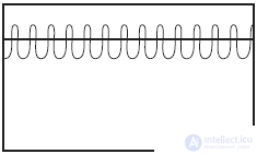
Fig. 5.14. Форма колебаний высокого тона
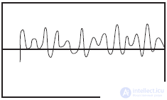
Fig. 5.15. Алгебраическая сумма колебаний высокого и низкого тонов (DTMF)
Сигналы низкого тона (от R1 до R4) относятся к группе рядов. Сигналы высокого тона (от С1 до С4) образуют группу колонок.
Table 5.2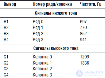
Любая комбинация частот может быть получена при использовании матрицы выключателей 4 х 4 или соответствующей клавиатуры (рис. 5.16). Помните, что эта технология была заимствована из телефонной индустрии, поэтому она была рассчитана на эффективное применение в телефонных линиях достаточно посредственного качества.
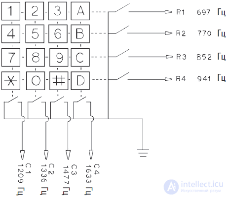
Fig. 5.16. Матрица клавиатуры 4х4, показывающая отдельные частоты DTMF
Стандартные телефоны с тональным набором используют матрицу клавиатуры размером 3х4. Такая матрица позволяет кодировать сигналы частот всех возможных рядов, но только трех вертикальных колонок (см. рис. 5.17). Клавиатура размером 3х4 более доступна и будет использоваться во всех схемных решениях, описанных ниже.
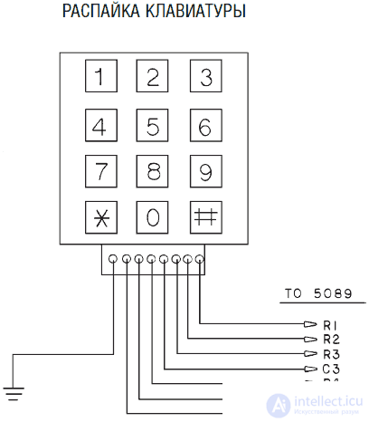
Fig. 5.17. Распайка телефонной клавиатуры 3х4
Не все клавиатуры от телефонов работают подобным образом, поэтому некоторые из них окажутся непригодными для наших схем. Например, некоторые клавиатуры имеют отличающуюся распайку выводов и требуют соответствующих ИС. По этой причине, если вы используете клавиатуру, то должны убедиться в ее правильном функционировании.
Изготовление кодера DTMF достаточно просто (см. рис. 5.18). Для этого потребуются клавиатура, кварцевый резонатор и ИС типа 5089. Цоколевка ИС 5089 показана на рис. 5.19. При использовании стандартной клавиатуры от телефона размером 3х4 вы потеряете возможность генерации 4-х DTMF кодов, связанных с отсутствующими клавишами, что снижает максимально возможное количество комбинаций до 12.
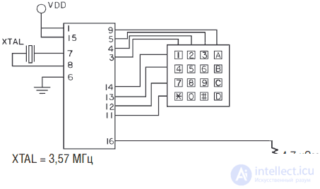
Fig. 5.18. Кодер DTMF, использующий матрицу клавиатуры 4х4
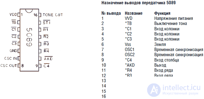
Fig. 5.19. Цоколевка кодера DTMF ИС 5089
In fig. 5.20 изображена тестовая схема кодера, в которой использованы восемь кнопочных выключателей. Эти выключатели в данном случае заменяют клавиатуру, с их помощью вы сможете проверить работу кодера и работу схемы приемника (декодера). Помните, что необходимо использовать кнопочные выключатели, работающие на замыкание. Для нормальной работы необходимо соединение одного из выводов R1-R4 и C1-C4 c землей, что осуществляется соответствующими кнопками.
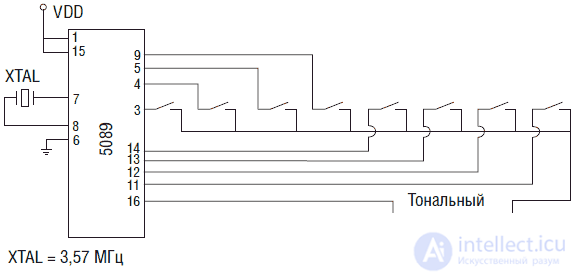
Fig. 5.20. Схема кодера, использующего восемь кнопочных переключателей
ИС способна генерировать одиночные тоны, что обычно предпринимается для целей тестирования. Например, чтобы сгенерировать тон частоты 1336 Гц, соответствующий выводу С2, необходимо замкнуть на землю вывод С2 и любые два вывода из группы рядов R1-R4. Такая операция и приведет к генерации чистого тона 1336 Гц. То же самое можно проделать для генерации тона из группы рядов. Для этого необходимо заземлить любые два вывода из группы колонок и необходимый для генерации заданной частоты вывод из группы рядов.
Декодирование сигналов DTMFДекодирование сигналов DTMF является немного более сложным, чем кодирование. Наиболее простым решением может явиться использование единственной ИС, на этот раз типа G8870 (рис. 5.21).
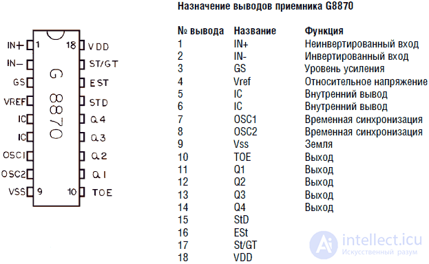
Fig. 5.21. Цоколевка декодера DTMF ИС G8870
ИС декодера имеет 4-битный выход с фиксацией состояния, обозначенный Q1-Q4. Q4 является старшим битом. Ток выходов Q1-Q4 достаточен для зажигания маломощных светодиодов. In fig. 5.22 показана основная схема приемника. Комбинация зажженных светодиодов, подключенных к выходам Q1-Q4, образует двоичное число. В таблице 5.3 приведены соответствия между кодами DTMF и соответствующими им двоичными числами. Схема построена так, что включенному светодиоду соответствует двоичная единица.
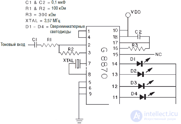
Fig. 5.22. Схема приемника с 4-битным выходом
Выводы Q1-Q4, соответствующие 4-битному числу, с выхода ИС G8870 могут быть непосредственно подключены к входным линиям микроконтроллера типа PIC 16F84. Такой микроконтроллер легко «читает» двоичные коды. Мы вернемся к использованию PIC микроконтроллеров в гл. 7
Система связи на ИК лучах, которую мы будем рассматривать в следующих разделах, в комбинации с PIC микроконтроллером, разбираемым в гл.7, позволяет создавать программно управляемую систему коммуникации между роботами, используемыми в играх типа «салки» и в задачах следования за лидером.
Таблица 5.3. Сигналы DTMF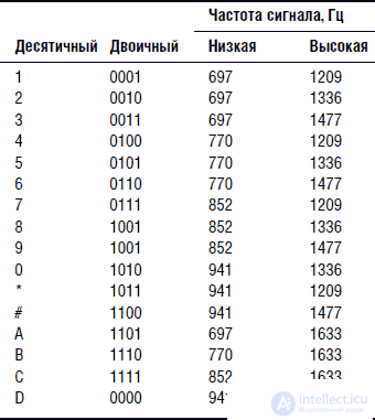
Если чтение двоичного кода представляется слишком утомительным, можно добавить десятичный цифровой индикатор. Выход ИС можно присоединить к двоично-десятичному дешифратору для 7-сегментных индикаторов типа 7448. ИС 7448 в свою очередь соединена с 7-сегментным индикатором типа MAN 74 (с общим катодом). Схема, включающая две ИС, позволяет осуществлять цифровую индикацию (см. рис. 5.23).
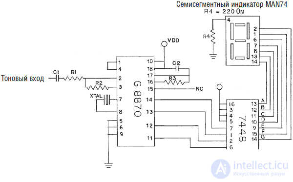
Fig. 5.23. Схема приемника с цифровой индикацией
Для проверки соедините выход ИС 5089 (вывод 16) с входом ИС G8870 и сгенерируйте сигнал DTMF с помощью кнопочных выключателей или клавиатуры. Декодер должен отобразить этот сигнал с помощью светодиодов или цифрового индикатора.
Использование ИК излучателяКак только вы убедились в работоспособности устройства, можно добавить в схему приемник и передатчик ИК излучения. Выход ИС 5089 соединяется с базой NPN транзистора, в эмиттер которого включается мощный ИК светодиод (см. рис. 5.24). Можно подключить диод непосредственно к выходу ИС 5089, но излучаемая мощность в этом случае будет мала. NPN транзистор производит добавочный ток для питания светодиода.

Fig. 5.24. Схема ИК передатчика DTMF
In fig.Figure 5.25 shows the input part of the IR receiver circuit. The IR phototransistor is connected to a KPO operational amplifier. This combination of elements allows you to control the IC 8870 through the IR channel at a distance of about a meter.
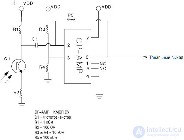
Fig. 5.25. Diagram of the input part of the DTMF IR receiver
Using the IR connection, you can press a key with a specific number on the keyboard and see the corresponding number displayed on the digital display. Check the quality of the IR connection in the direction and maximum distance. Increasing the communication range can be achieved by placing the IR LED and phototransistor in separate reflectors. A reflector from an old flash lamp works well for this purpose.
Устройство ДУ можно получить, добавив в схему ИС 4028, которая представляет собой двоично-десятичный дешифратор. Это означает, что при подаче параллельного двоичного кода на вход ИС (этим кодом зажигались светодиоды на рис. 5.22) на одном из выходов появится сигнал, соответствующий десятичной цифре. ИС 4028 имеет 10 выходов, обозначенных цифрами от 0 до 9. В зависимости от 4-битного кода на входе 4028, она выдает сигнал высокого уровня на одном из выходов (см. рис. 5.26).
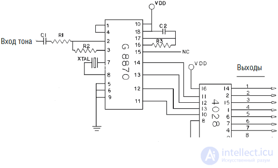
Fig. 5.26. Схема приемника DTMF с преобразованием шестнадцатеричного кода в десятичный
Удалять из схемы ИС 7448 и цифровой индикатор нет необходимости, поскольку ИС 8870 имеет достаточно мощный выход для подачи сигнала на обе ИС 7448 и 4028. При тестировании выхода ИС 4028 цифровой индикатор может оказаться очень удобным. Чтобы не загромождать чертеж, на рис 5.26 показана связь ИС 8870 только с ИС 4028.
Выходы ИС 4028 могут непосредственно использоваться для управления переключателями или другими частями схемы. Однако это не является удачным решением, поскольку при нажатии следующей клавиши (цифры) выход, соответствующий предыдущей цифре, отключится (сбросится на низкий уровень).
Для решения этой проблемы можно использовать D-триггер типа 4013 (рис. 5.27). Триггеры являются основными элементами компьютерной памяти. В этой схеме в качестве триггера используется двоичный счетчик. После первой логической «1» на выходе ИС 4028 выход триггера перебросится также в логическую «1». Когда на выходе 4028 появится логический «0», что соответствует включению другого канала, ИС 4013 будет удерживать логическую «1» на выходе (фиксация состояния).
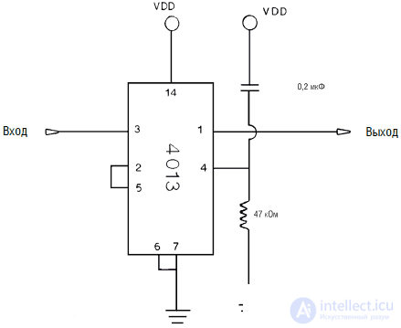
Fig. 5.27. Схема триггера ИС 4013
Чтобы опять перебросить выход 4013 в «0», необходимо просто включить соответствующий канал еще раз. Второй импульс, пришедший на вход ИС 4013, переключит ее выход в низкий уровень («0»). Чередование высокого и низкого уровней на выходе ИС 4013 происходит при каждой подаче «1» на ее вход.
Машинное зрение
Моделирование человеческого зрения при помощи машины является сложной задачей. Совершенно недостаточно присоединить видеокамеру к компьютеру и рассчитывать, что такая установка будет «видеть». Нейронные системы и программы ИИ должны считать видеоизображение и подвергнуть его обработке. Сейчас машинное зрение используется в ограниченных и специализированных областях.
В главе 1 я говорил о компьютерной системе Papnet, которая использует специальное нейронное программное обеспечения для анализа изображений эмульсионных мазков, обеспечивая точность, недоступную человеку-оператору. Некоторые исследователи разрабатывают системы управления автотранспортом, на основе визуального контроля очертаний дорожного покрытия.
Прежде чем мы сможем попытаться моделировать человеческое зрение, нам потребуется создать систему стереоскопически размещаемых камер (в дополнение к системе распознавания образов, что само по себе является непростой задачей). Некоторые исследования подобного рода проводятся в Массачусетсом технологическом институте, там создан робот-гуманоид COG. С помощью двух стереоскопических камер можно получить два изображения, которые обрабатываются и затем сравниваются для получения трехмерной картины. Этот процесс аналогичен получению трехмерных изображений у человека. Для определения глубины пространства каждая камера должна быть смонтирована на подвижном карданном подвесе, что позволит камерам сводить оптические оси (конвергировать) и фокусироваться на объекте. Для определения расстояния до объекта используется значение величины конвергенции.
Problems of machine vision are fertile ground for development. Currently, most of these systems require powerful computers and solve image processing tasks.
Body sensation
The sensation of the body includes a sense of its position relative to the reference points and in space. The simplest “body feeling” can be modeled in a robot with multiple tilt sensors (see Fig. 5.28). At the very least, the robot will be able to “understand” whether it is tilted forward or backward, is on the “stomach” or on the “back”, upside down or on the right side. Based on the received information about the body position, the robot can perform some actions and change its position.
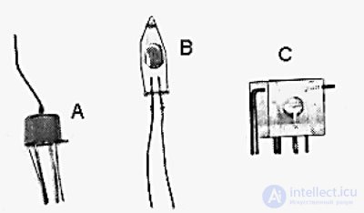
Fig. 5.28. Tilt sensors
Direction Indicator - Magnetic Field
Direction information can be pushed through with an electronic compass using Earth's magnetic field. This will allow the robot to move in a given direction or receive information about the direction of movement.
The simplest device is a digital compass model 1490 (Fig. 5.29). The compass is a solid-state Hall sensor. The device is equipped with four conclusions corresponding to the position of the four main sides of the world: north, east, south and west. When using a small logical device, you can define eight directions.
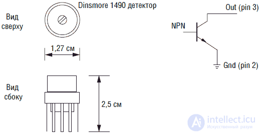
Fig. 5.29. Digital compass 1490
The compass is damped in such a way that its characteristics are close to those of a liquid-filled compass. The compass requires about 2.5 s to rotate at an angle of 90 °. Damping prevents torsional vibrations of the device and the effect of jitter near the indicated direction. The device is sensitive to the angle of inclination. When the angle of inclination is more than 12 °, the measurement errors exceed the permissible ones.
At the bottom of the device are twelve pins, grouped into four groups of three pins. If you look at the compass from above, its conclusions in the group are marked 1, 2 and 3. Pin 1 is connected to the power source (5 V), pin 2 is connected to ground. Conclusions 3 of each group are informational outputs. These outputs are similar to the NPN circuit of a transistor connected to a common collector. In such switching on, the output does not produce voltage, but it can pass a considerable current (up to 20 mA), which is sufficient for igniting the LED.
The test circuit is shown in fig. 5.30. The sensor maintains operability in the range of supply voltage from 5 to 18 V. In this case, a 9 V battery and a 5 V voltage regulator are used, made on the IC 7805.
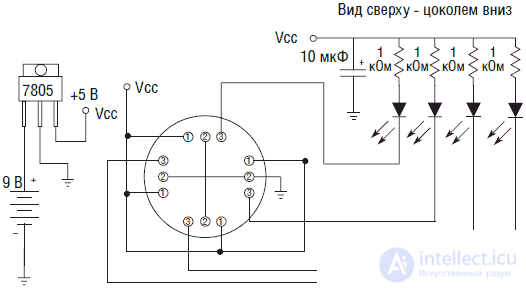
Fig. 5.30. Digital compass test circuit with 4 LEDs
Take as a rule: in order to safely pair the circuits with computer devices, do not set operating voltages higher than 5 V. For example, if we pair the electronic compass with the PIC interface of the microcontroller and use 9 V supply voltage, too high a voltage at the compass output can burn the input microcontroller circuit.
LEDs are used to indicate the direction in the test circuit. As the device rotates, each of the main directions (sides of the world) is indicated by one LED. Intermediate directions cause the ignition of two LEDs.
Verification and calibration
Using the normal compass, find the direction to the north. Turn the device until one LED lights up. For convenience, I use the moment of ignition of the LED furthest from the sensor. If you do the same, you will automatically receive the sequence shown in Fig. 5.31.
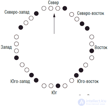
Fig. 5.31. LED Sequence
Computer interface
The four lines of the compass output form a 4-bit binary number (nibble), which can be easily read using a microcontroller, computer, or other circuit (see Table 5.4). Until the review of the PIC microcontroller 16F84 operation scheme in ch. 7 we will not consider the connection scheme.
Table 5.4. LED assignment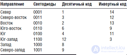
Electronic analog compass type 1525
In most cases, the direction information provided by the 1490 device is more than enough for the robot to work properly. However, in some cases, a more precise determination of the direction is required, in which case you can use an analog electronic compass of the 1525 type (see. Fig. 5.32).
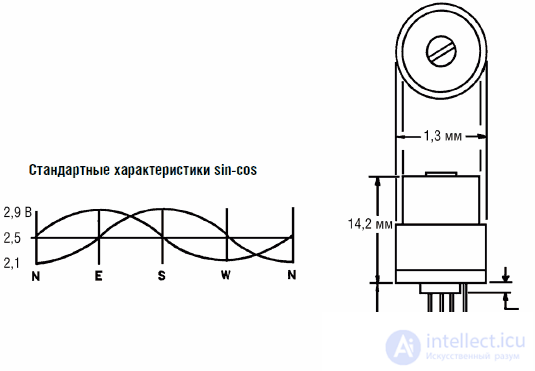
Fig. 5.32. Electronic analog compass type 1525
The output of the 1525 device requires much more complex processing, but the advantage of such an electronic compass is that it determines the direction with an accuracy of about 1 °.
The output signal consists of two sinusoidal oscillations that are 90 ° out of phase with each other (see the position of the oscillation phases in Fig. 5.32). The amplitude of each oscillation depends on the direction of the device. If the amplitude of a quarter of the oscillation (phase 90 °) is converted by an 8-bit ADC, then the resolution of the device will be about 1 °.
Global Positioning System (GPS)
Using the global positioning system (GPS) will allow the robot to determine its location with great accuracy anywhere on Earth. The use of GPS in most cases is not really necessary, but reducing the cost of such systems makes their possible use quite realistic.
Speech recognition
The range of hearing of the human ear lies in the range from 10 to 15.000 Hz. Microphones and amplifiers can be used to record sound vibrations, and the range of “audibility” of a microphone, as a rule, exceeds the ear's capabilities. For robotics, the use of sound is a valuable tool.
In ordinary life, hearing is used primarily for communication (language). The creation of robotic speech recognition systems is now very popular. For this reason, we will devote an entire chapter (see Chapter 7) to the creation of speech recognition schemes and their interfaces. But, nevertheless, do not miss the following information, because the use of sound systems in robots can be very useful.
Sound and ultrasound systems
Sound can be used in games, determining distances, preventing collisions and avoiding obstacles. The robots are equipped with a dual-tone generator and receiver for playing “salki”. Each robot can generate and receive signals of two tones. Suppose tone A is 3000 Hz, and tone B is 6000 Hz. These tones are emitted at any collision of robots (contact switches are used).
The robot, which is the “sally” (leading), makes the sound of tone B in any collision of the “bumpers” with another robot. A robot that is “not driving” in this case makes the sound of tone A. Recall that at a collision, the “leading” robot makes a sound B. “Not leading” the robot hears the sound B, switches and becomes “leading”. In turn, the “leading” robot hears the sound of A and becomes “non-leading”. When two “non-performing” robots collide, everyone emits the sound of tone A, therefore their state does not change. It is clear that we used sound signals as an example. With the same success, you can use the communication system on the IR rays.
Ultrasound is often used to determine distances and detect obstacles. Many designers chose to use Polaroid ultrasonic modules (see fig. 5.33). Such modules are used in Polaroid cameras to quickly determine the distance to the object and focus the lens in order to get a clear image. When connected to a microcontroller interface, such devices are capable of measuring distances with great accuracy.
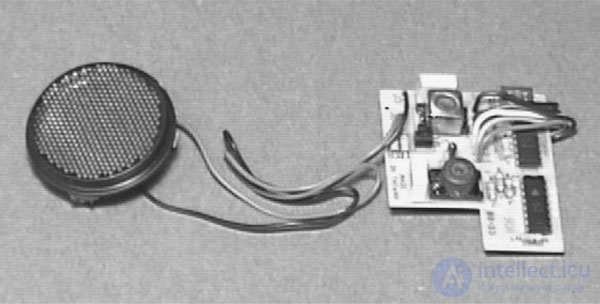
Fig. 5.33. Polaroid type ultrasonic range finder
Such Polaroid sensors are very convenient for use in robots to determine distances. The device is capable of measuring distances up to 10 m. When using a servo motor or a stepper motor, the device can be rotated in the manner of a radar to create a navigation map or to detect an open passage.
Each time you turn on the ultrasonic Polaroid transducer emits an audible click. These constant clicks coming from the sensor seem annoying to me. Although the module operates in the ultrasonic range, the initial excitation process of the ultrasonic emitter is accompanied by audible sounds.
It is relatively easy to create an ultrasonic collision avoidance system, which, being an ultrasonic cavity, works "quietly". The basic scheme repeats the collision avoidance scheme on IR rays, with the difference that we use sound instead of light. In fig. 5.34 shows the functional diagram of the device. The transmitter sends a 40 kHz signal to an ultrasound transducer (emitter). Another transducer (receiver) is located next to the transmitter emitter. When the robot approaches a wall or an obstacle, a 40 kHz signal is reflected and enters the receiver, which causes an increase in the amplitude of its output voltage. When the voltage exceeds the threshold value, the comparator will transfer to another state, signaling the presence of an obstacle.
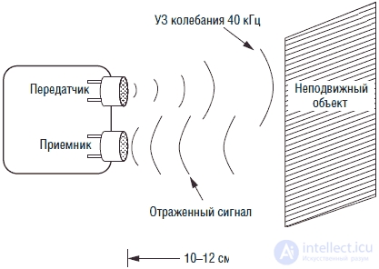
Fig. 5.34. Ultrasonic obstacle detector circuit
Ultrasound receiving unit
Ultrasonic receiving unit (see. Fig. 5.35) is used to fine tune the transmitter. The fact is that ultrasonic transducers have a resonant frequency of 40 kHz. If the frequency is different from the resonance (± 750 Hz), then the efficiency of the converter drops sharply. Fine tuning the transducer to the maximum resonance is not difficult if you use the procedure described below. This will require an avometer, measuring direct current, with a scale of 2 V.
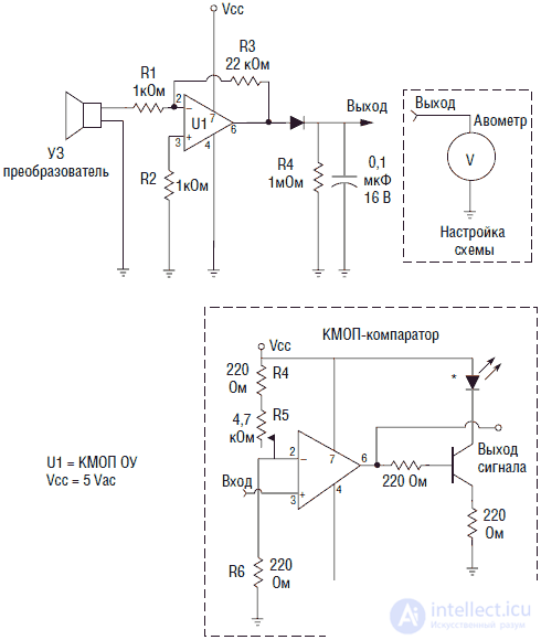
Fig. 5.35. Ultrasound receiver circuit
Since the transducers have a very narrow bandwidth, (the resonance lies around the frequency of 40 kHz), the use of a PLL loop (IC LM567) is not necessary. The converter itself suppresses signals outside its frequency range.
In the receiving unit used OU CMOS structure. The pinout of the 8-pin amplifier body is similar to the universal type 741 IC (but is not a replacement for the OU 741). OU is included in the circuit with an inverted input and has a gain of about 22.
UZ transmitting unit
The ultrasonic transmission unit is made on a CMOS 555 type IC, which is included in the generation mode. For precise frequency control used trimming resistor R2 4.7 kOhm (see. Fig. 5.36).
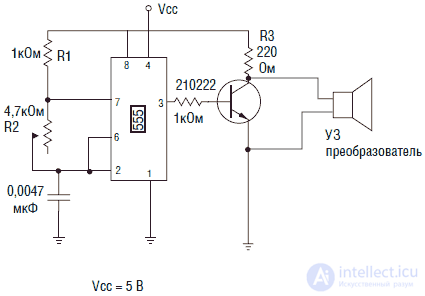
Fig. 5.36. Ultrasonic transmitter circuit
Arrange ultrasonic transducers (emitters) towards each other at a distance of 10–15 cm (see. Fig. 5.37). Connect the voltmeter as shown in the inset to fig. 5.35 (comparator must be disconnected). Set the meter to measure DC voltage. The output voltage will be about 2 V, respectively, you need to set the desired measurement limit. Turn on both devices at the same time. Adjusting the transmitter using R2, achieve the maximum output voltage on the voltmeter, which should be about 2 V.
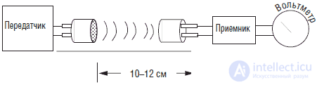
Fig. 5.37. Verification of the operation of the ultrasonic device
After setting up the transmitter, we need to set up a comparator circuit. Disconnect the voltmeter and connect the comparator. Arrange the ultrasound transducers in a row, in the same direction, about 15 mm apart. Position the object with a flat edge about 75 mm in front of the ultrasonic transducers. Turn on the receiver and transmitter and adjust the receiver resistor R5 before igniting the super miniature LED.
To check the operation of the circuit, remove the object located in front of the emitters. In this case, the LED should go out. Move the object to a distance of 12–15 cm and adjust the R5 again until the LED lights up. Remember that the receiver is very sensitive to the angle of reflection. If the object has an acute angle, then the ultrasonic signal may be reflected “laterally” from the receiver. As the object approaches, the angle of reflection becomes less critical.
The device is able to detect objects at distances up to 20 cm. At large distances, the angle of reflection becomes very critical. I used the perpendicular position of the emitters. For different distances you can slightly rotate the emitters.
When an object is detected at a distance of up to 15 cm, the device consistently outputs a TTL high level signal, which lights the LED. This signal can be easily used to control a neural network or a microcontroller.
Location of ultrasonic sensors
Obvious ways to use ultrasonic transducers (sensors) is to detect obstacles in front, behind and on the sides of the robot. Another application that is not so obvious is surface monitoring. If the ultrasound sensor attached to the front is tilted slightly downwards, it can provide information about the state of the surface on which the robot moves. If the robot reaches a break or a “step,” the normally high signal becomes low, informing the CPU of the need to stop movement.
Touch and feeling of pressure
The amazing accuracy and fidelity of the sense of touch in humans can hardly be achieved in the design of the robot. However, there are several types of simple sensors that can be used to detect touch and pressure. Touch sensors are commonly used in robots to detect obstacles along the way, which allows the robot to avoid collisions.
More sophisticated touch and pressure sensors are used in the design of hands and hands. Such sensors allow the “arm” of the robot to capture and hold objects with sufficient force without the risk of damaging them. A simple touch and pressure sensor can be made from electrostatic (conductive) foam rubber. Similar foam rubber is used when packing ICs to protect them from static electricity. Such foam rubber has a certain electrical conductivity, which varies with compression.
It is necessary to use a loose (soft) type of foam rubber, since it has a porous structure and has sufficient flexibility. When pressed, the foam rubber is compressed, which leads to a change in resistance between the electrodes placed on it.
In fig. 5.38 is a drawing of a simple pressure sensor. Conductive plates (electrodes) can be made of foil material for printed circuit boards, aluminum foil or something similar. More accurate touch and pressure sensors will be discussed later in this chapter.
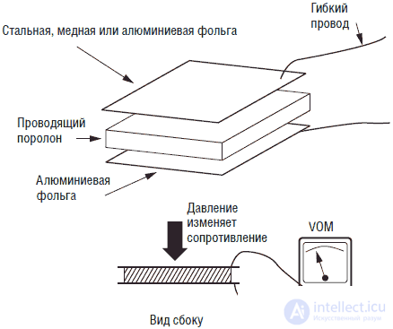
Fig. 5.38. Pressure sensor based on conductive foam
Piezoelectric materials
There is a large variety of piezoelectric sensors. Piezoelectric sensors can record vibrations, jolts and thermal radiation. Pennwall produces a unique product called a piezoelectric film. It is a plastic coated with aluminum in such a way that it acquires piezoelectric properties.
The material has sufficient sensitivity to detect thermal radiation of a person moving in front of the film surface. Many commercial security light-on devices, sold in hardware stores, use sensors in the form of a piezoelectric film placed behind a Fresnel lens to detect human presence from its thermal radiation. Such devices automatically turn on the light when a person enters the "field of view" of the device.
Light switches
Switches of instantaneous action (push-button) by type form groups of touch sensors, direction indicators and limit switches A variety of types of such switches provides the freedom of their choice. The most frequently used in the robotics are switches of instant action of the lever and push-button types (see. Fig. 5.39).
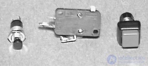
Fig. 5.39. Snap Action Switches (Buttons)
Bend sensors
Bending sensors are passive elements of the resistive type, the resistance of which increases with bending or twisting (see fig. 5.40 and 5.41). Such sensors are usually used in special gloves of virtual reality systems to determine the position of fingers in a glove, and can be easily adapted to the needs of robotics. Such a bend sensor can be a genus of tentacles and warn the robot about the presence of obstacles.

Fig. 5.40. Bend sensor
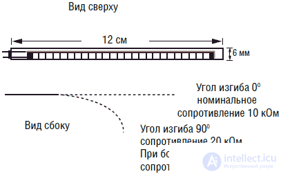
Fig. 5.41. Bend Sensor Resistance Graph
Such devices resemble a cat's mustache. Cats use whiskers to determine if a passage is wide enough so that it can be passed there. Если усы по обеим сторонам кошачьей мордочки сигнализируют о наличии препятствия, то кошка туда не пойдет. Подобным образом можно использовать датчики давления и в роботах.
Тепловые датчики
Наиболее известными тепловыми датчиками являются термисторы (см. рис. 5.42). Это устройство пассивного типа изменяет сопротивление пропорционально температуре. Существуют термисторы, имеющие положительный и отрицательный температурный коэффициенты (см. рис. 5.43). Температурное излучение также может быть обнаружено с помощью пьезоэлектрических материалов, о чем говорилось выше.
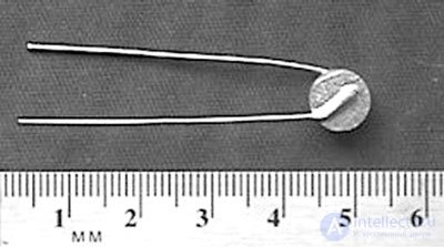
Fig. 5.42. Термистор
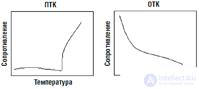
Fig. 5.43. Графики температурной зависимости сопротивления термистора с положительным и отрицательным ТК
Датчики давления
Для измерения сил хорошо подходят датчики давления, изображенные на рис. 5.44. «Чувствительный» элемент датчика расположен на специальной подложке размерами 14х14 мм на одном конце устройства. С увеличением приложенной силы сопротивление датчика падает. Датчики выпускаются для различных диапазонов приложенных сил: от 0–4 Н до 0-4000 Н.
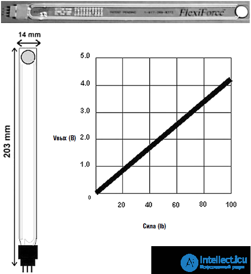
Fig. 5.44. Датчик давления Flexiforce
Датчики запаха
Диапазон реакций на запахи человеческого носа в настоящее время недостижим ни одной из известных искусственных сенсорных систем. Известны простые газовые датчики, способные обнаружить присутствие токсичных газов (см. рис. 5.45). Подобные датчики могут быть использованы для создания автоматических (роботизованных) систем вентиляции.
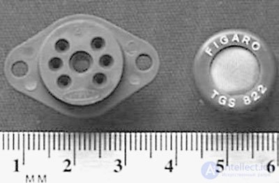
Fig. 5.45. Датчики ядовитых газов
Пример включения простого газового датчика представлен на рис. 5.46. Для создания чувствительности резистивный элемент должен быть подвергнут нагреву. Устройство снабжено встроенным подогревателем, питающимся от отдельного источника. Подогреватель потребляет около 130 мА при стабилизированном напряжении питания 5 В. Показания резистивного элемента могут быть считаны аналогично описанному выше.
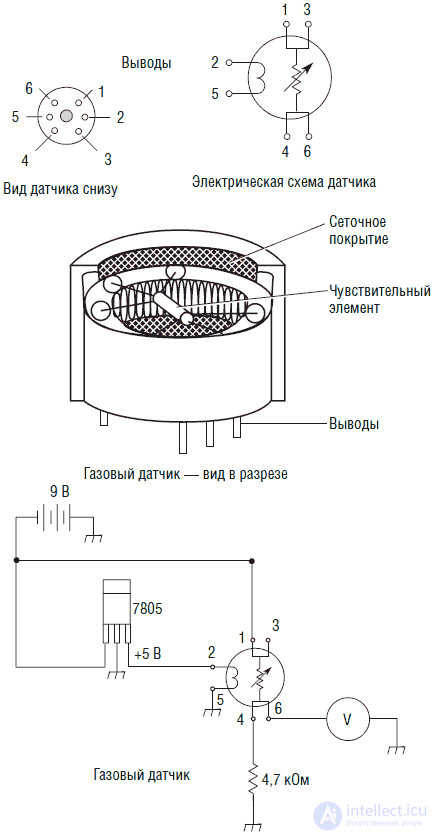
Fig. 5.46. Проверка работы датчиков токсичных газов
При использовании простых схем возможности газовых датчиков раскрываются не полностью. Дело в том, что одиночный датчик не выдает достаточно точных показаний. Иными словами, показания датчиков немного изменяются от экземпляра к экземпляру. Это «аналоговое» свойство группы датчиков может быть использовано для создания более чувствительного устройства.
Рассмотрим группу из восьми датчиков, резистивный элемент каждого из которых подключен к АЦП. В данной ситуации использование компаратора неэффективно, поскольку нас как раз интересует небольшая разница в показаниях отдельных датчиков. Для калибровки устройства необходимо выпустить небольшую порцию известного газа (запаха) на все восемь датчиков. Показания каждого из них преобразуются АЦП и записываются в компьютер. Разница показаний датчиков формирует профиль для каждого анализируемого запаха.
Подбор профиля хорошо реализуется в технологии нейронных сетей. Нейронная сеть может быть создана таким образом, что окажется в состоянии определять не только интенсивность, но и распознавать различные запахи.
Датчики влажности
Пассивные датчики влажности с резистивным выходом представляют собой относительно новую разработку и доступны к приобретению.
Проверка датчиков
При разработке и изготовлении систем чувствительных датчиков представляется разумным производить их тестирование перед установкой в систему робота. Одним из способов, который я осуществил, являлось создание небольшого передвижного робота, единственной функцией которого была проверка работоспособности и характеристик датчиков. Таким образом, оказалось возможным оценить время срабатывания датчика и его надежность до установки в более сложную конструкцию робота.
Робот способен тестировать «ударные» выключатели, световые выключатели, датчики изгиба, а также системы датчиков предотвращения столкновений, использующих ультразвук и ИК лучи. Прочие типы датчиков могут потребовать тестовой платформы больших размеров.
Изготовление робота-тестера
Я назвал конструкцию этого небольшого устройства роботом-тестером. В основе ее лежит небольшой электрический автомобиль, который можно приобрести менее чем за $10 (см. рис. 5.47).
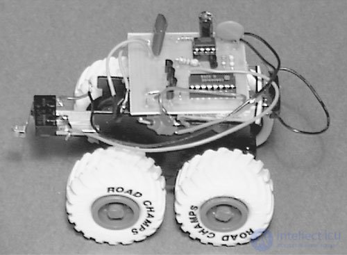
Fig. 5.47. Тестер
Принципиальная схема робота-тестера изображена на рис. 5.48. Сенсор подключается к входу запуска таймера ИС типа 555, использованной в режиме одновибратора. На выходе схемы (вывод 3) присутствует напряжение низкого уровня до момента подачи отрицательного запускающего импульса на вывод 2. После этого на выводе 3 генерируется одиночный положительный импульс длительностью порядка 1 с.
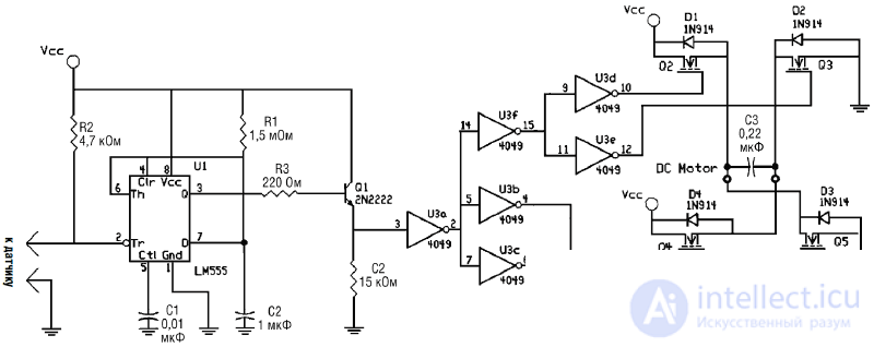
Fig. 5.48. Схема работы тестера
Вывод 3 ИС 555 соединен с NPN транзистором типа 2N2222. Выходной сигнал снимается с эмиттера транзистора и поступает на одну из 6 схем «НЕ» инвертора, выполненного на ИС 4049. Выходы буферов схем «НЕ» 4049 поступают на МОП полевые транзисторы, включенные по схеме моста, которые управляют вращением двигателя привода.
При наличии низкого уровня на выходе ИС 555 транзисторы моста включают двигатель для движения «вперед». Тестируемый датчик подключен к входу запуска 2 ИС 555. Датчик включен таким образом, что при замыкании или коммутировании он выдает отрицательный импульс (садится на землю). Этот импульс на выводе 2 запускает одновибратор, который в свою очередь выдает положительный импульс длительностью 1 с на вывод 3. Данным импульсом транзисторы перекоммутируют двигатель на 1 с для движения «назад».
Подобный тестер может быть использован для проверки большинства датчиков и преобразователей.
Усовершенствование робота-тестера
Когда я разрабатывал конструкцию робота-тестера, то предполагал что большинство проверяемых датчиков будет использовано в конструкциях миниатюрных моделей. Однако вышло по-другому. В процессе конструирования различных схем-прототипов, как правило, не хватало времени для изготовления печатной платы, не говоря уже о минимизации размеров устройства.
Если бы я создал другого робота-тестера, я бы, несомненно, использовал большую модель электрического автомобиля в качестве платформы. Наличие достаточного места позволило бы с большим удобством проверять различные типы датчиков и иных схем.

Comments
To leave a comment
Robotics
Terms: Robotics