Lecture
Speech is the ideal way to control and communicate in robotics. The speech recognition device (OCR) scheme to which this chapter will be devoted functions independently of the basic “intelligence” of robots (CPUs). This fact is positive because the robot's CPU resource is not used to solve the speech recognition problem. The task of the CPU is to occasionally interrogate the bus output device recognition to detect possible incoming speech commands. This process can be optimized by connecting one of the recognition device's output buses to the CPU interrupt bus. In this case, the recognized word will cause an interrupt, notifying the CPU that the command has been spoken. The advantage of using an interrupt is that it eliminates the need to constantly poll the status of the recognition device, thus saving the CPU resource.
Another advantage of a separate complete speech recognition device (OCR) unit is its programmability. You can program and “teach” ORA to recognize those specific words that you intend to use as commands. It is easy to create an interface interfacing an URR with a robot's CPU.
Most of today's speech recognition systems appearing on the market are special software that requires a working computer (usually a PC or compatible system) and a sound card. The URR system is basically a program, although for its work it requires some “hardware” (sound card). Such programs usually operate under the DOS or Windows platform, while occupying a certain part of the memory and CPU resource, while at the same time allowing other programs to work simultaneously, such as Word or Lotus. The simultaneous operation of the OAI program slows down the work of other programs using these OYA programs.
Speech recognition is not only used in robotics, but finds many uses outside of it. Speech recognition will find application as a way to control robots in virtual reality (VR), devices, games, tools and computers. This technology has a very good potential in the long term, so companies are developing speech recognition methods. The ability to control and give commands to a computer (or instrument) directly by voice will make the process of controlling such a device much simpler, more efficient and convenient. This type of voice control basically allows the user to perform other operations in parallel (i.e., with voice work with a computer or a device, the eyes and hands remain “free” for other work).
In this chapter, we will look at three projects for constructing speech recognition devices. The first project is the actual scheme of OAI. The second project is devoted to the interface that connects OAW with a mobile chassis taken from a radio-controlled car model. Finally, the third project deals with a universal interface board for a set of OAIDs.
Project 1: Programmable Speech Recognition Scheme
The first project is the creation of a programmable speech recognition circuit. The term "programmable" is used in the sense that you can program the T "7V to recognize 40 individual words of your choice. The“ heart ”of the device is the only IC of the HM2007 type - speech recognition IC. The IC provides recognition of words with a length of 0.96 s or 1.92 s.
With a word length of 0.96 s and an 8Kx8 static random-access memory (RAM), up to 40 individual words can be recognized. It is possible to enable the recognition of longer words with a length of 1.92 s. Although the number of recognizable words is reduced to 20, it is possible to recognize not only individual words, but also short phrases. In our project we will use a recognition interval of 0.96 s, which forms a library of 40 recognizable words.
Learning speech perception
We take our own speech recognition abilities as a matter of course. However, the process of isolating the speech of one person in a crowd gathered at a party lies far beyond the capabilities of modern OAI systems. Such systems, just like us, face the difficult task of separating signals and filtering extraneous noise.
For reliable operation of the OCR device, the distance from the speaker to the microphone should be less than 30 cm. When using OCR on the mobile chassis of the robot, we included two small radio stations such as Walkie-Talkie. The output of one of the radio stations is connected to the microphone input of the OCR. Another radio station is used to actually give voice commands to the robot. This configuration removes the problem of remoteness from OCR and reduces extraneous noise.
The task of speech recognition does not coincide with the task of "understanding" of speech. If a computer is able to respond to a sound command, this does not mean that it “understands” it. Future speech recognition systems may acquire the ability to recognize semantic and intonational shades of the meaning of words, i.e. they will respond in the manner of "Do what I mean, not what I say." Nevertheless, such systems are a matter of the distant future.
Speech recognition depending and regardless of the speaker
In the process of speech recognition, two tasks can be distinguished: speech recognition for a specific speaker and independently of him. The speech recognition system “learns” the speech of a specific person who will use it in the future. Such systems are able to memorize a significant number of commands and recognize them with a probability of more than 95%. The disadvantage of this approach is that the system accurately recognizes the commands of only the person who carried out its “training”. This approach is most common for systems based on the use of personal computer software.
A system that does not depend on the speaker “learns” to understand the commands, regardless of who says them. For this reason, the system should be able to adequately respond to a wide range of speech patterns, including the intonational identity and features of the pronunciation of keywords. In this case, the set of command words, as a rule, is much smaller, however, achieving the necessary accuracy of response is possible in this case as well. For industrial purposes, recognition systems are more often required that are independent of the speaker.
Our OAI refers to systems that are tuned to the speech of a particular person. We can make our system partly “independent” by reserving several speech patterns for each keyword, each of which is programmed separately and takes its corresponding place. Each of these speech patterns will trigger the execution of the same command.
Types of speech recognition
URR systems have one more specific limitation that relates to the type or style of recognizable speech. The existence of three types of speech is assumed: separate, coherent and continuous.
Separate speechSystems of URR, operating with separate speech, process words that are pronounced separately. Today it is the most common system of OAI. In this case, the user needs to pause between the command words. In our PP device, just separate words will be used.
Connected speechConnected speech occupies an intermediate position between the pronunciation of individual words and a continuous stream of speech. In this case, the user can pronounce groups of words as commands. The HM2007 can be set to recognize words or phrases up to 1.92 seconds in length. In this case, the command dictionary is reduced to 20 units.
Continuous speechWe use the continuous flow of conversational speech in everyday life. For ORA, continuous speech recognition is a fantastically difficult task, since in such a flow words tend to merge. For example, the phrase “Hello, how are you doing?” Phonetically sounds like “Hello, how do you live”. Such continuous speech flow recognition systems have already appeared on the market and are in the process of continuous development.
Schematic solution OID
The demonstration circuit is made on the IC HM2007, included in the manual mode. In this mode, for programming the HM2007 IC, a microphone and a simple keyboard are used.
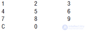
KeyboardThe keyboard is a standard telephone keypad, which has 12 normally open buttons.
When the power is turned on, the HM2007 IC performs on-board static OP testing. After the testing is completed, the digits “00” on the seven-segment on-board indicator light up, the red LED lights up, and the device waits for a command.
TrainingPress "1" (the indicator will light "01"), and the LED goes out. Then press "T" (Training), and the LED will light up again.
Hold the microphone close to your mouth and say the key (learning) word. Suppose the word “computer” is used as a teaching word. Speak "computer" into the microphone. If the device accepts the word, it will cause the LED to flash. The word computer is programmed as word number "01". Now, if OAI "hears" the word "computer", then it will display the number "01" on the indicator.
If the diode does not flash after pronouncing the word "computer", then either try to repeat this word louder, or start again - type "01" and then "T".
Continue introducing new word patterns in OAW. For the second word, press “02” and then “T”. Let me remind you that the device can memorize 40 words. It is clear that there is no need to enter all 40 words. Enter the number of words you need and proceed to the next step.
Test recognition functionSay one of the previously memorized words into the microphone. The corresponding number should be displayed on the digital indicator. For example, the keyword “directory” was entered at number 25. Accordingly, pronouncing the word “directory” should ignite the number 25 on a digital indicator.
Error codes• 55 = too long word
• 66 = word too short
77 = no matching words found
Memory clearYou can delete individual keyword entries by dialing the word and the CLR button. To completely clear the memory, dial 99 and the CLR button.
Features HM2007 ICThe HM2007 speech recognition IC is a single-chip, highly integrated CMOS IC. The IC has an analog input, a voice analyzer, a recognition unit and a control unit for system functions. IP can be used alone or under control of the CPU.
Specifications• Single-chip IC for speech recognition CMOS structure of a high degree of integration
• Speech recognition of a specific source
• External OP support
• Up to 40 recognizable keywords
• Maximum word length 1.92 seconds
• Ability to connect a microphone
• Ability to work in manual mode and running the CPU
• Response time less than 300 ms
• Power supply 5 V
Device designA PP device can be made based on the finished set of parts supplied by Images Company (see the list of parts at the end of this chapter). The schematic diagram is shown in Fig. 7.1. Installation of parts is convenient to carry out on the PCB.
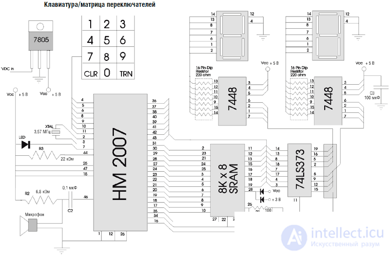
Fig. 7.1. Speech Recognition Diagram
Solder the keyboard leads to the printed circuit board according to fig. 7.2. The keyboard has seven conductors that connect to the HM2007 IC on the printed circuit board. Each keyboard pin corresponds with the corresponding pin of the HM2007 IC.
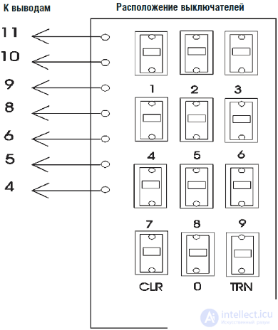
Fig. 7.2. Keyboard for URR
In fig. 7.3. shows the location of the parts on the printed circuit board from the components. In fig. 7.4 shows the OAI assembly.
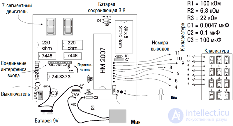
Fig. 7.3. Top view of the arrangement of parts on the PCB
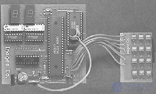
Fig. 7.4. PP device assembly
Demonstration scheme of OAI allows to perform experiments on speech recognition both in dependence and independently of the speaker. Usually the system is configured for a specific person under the assumption that he will use it.
We can use a different way and “train” the system to react relatively independently of the speaker. To achieve this goal, we will use four “learning” models for each team keyword.
To simplify the subsequent digital processing of messages, we use the following logic. To designate a keyword, we will use only the first digit (the lower order) on the digital indicator.
Thus, the models “01”, “11”, “21” and “31” will be recognized as the same keyword. Since only the low order is taken into account, in all cases the recognizable word will be denoted as “1”. Similarly, models “04”, “14”, “24” and “34” will correspond to the keyword “4”.
Problems may arise when recognizing error codes.
• 55 = too long word
• 66 = word too short
77 = no matching words found
In the logic used, these codes will be interpreted as the keywords "5", "6" and "7", respectively. There are two ways to solve the problem. The first method uses a special logic circuit (see Fig. 7.5), which generates a high level signal when 5, 6 or 7 digits appear in the high order, which is a blocking signal. This scheme generates a high level signal on the line when the numbers 5,6 or 7 appear, which is interpreted by the interface as a prohibition signal. Another way to solve the problem involves the use of a PIC microcontroller to read the 8-bit code from the output of the ORA. Any value greater than 40 will be interpreted as an error and accordingly ignored. We do not present here the interface circuits for the PIC microcontroller, since for anyone who knows how to work with the PICBASIC programmer and the PIC IC (see Chapter 6), this will not be difficult. In ch. 15 we use the built-in PIC in the OCR circuit used in the robot's hand control device.
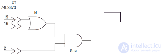
Fig. 7.5. Error Detector Based on BCD Senior Nibble State
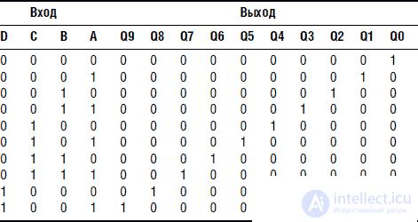
The 8-bit code at the output of the 74LS373 IC is a stateful code. This code is not a normal byte (8 binary bits), but is two 4-bit binary decimal codes (nibbles). Table 7.1 shows the correspondence between the binary decimal code and the standard binary number.
As you can see, up to 10 the binary and binary decimal codes are the same. At 10 in the binary coded decimal code, the unit “jumps over” to the higher nibble, and the younger nibble is reset. In a simple binary code, a similar operation (transferring the unit to the highest nibble and zeroing the younger one) is performed on the number 16. If the computer input is set to read binary numbers, errors will occur when the binary-decimal code is input.
Table 7.1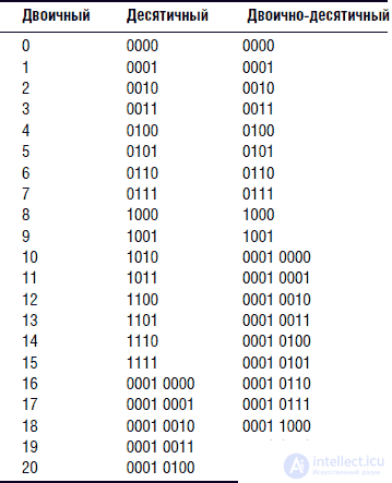
Project 2: Interface Diagram
The basis of the interface circuit is the decoder 4028. The IC 4028 reads the binary-decimal code of the low-level logic from the output of the IC 74LS373 located on the OCR board and outputs the corresponding high-level signals (see the correspondence table 7.2).
The schematic diagram of the interface is shown in Fig. 7.6. Inputs A, B, C, and D of the IC 4028 are connected to the lower nibble of the binary-decimal IP code 74LS373. When I disassembled the radio-controlled model of the car, I discovered several wires that, when energized, provide the basic functions of the movement. The robot car has four driving modes: moving forward, turning right, turning left and reverse.
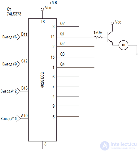
Fig. 7.6. Redesigned car interface model
Each mode of movement is provided by the appropriate inclusion of the engine or engine-solenoid combination. Turn-on control can be done with an NPN transistor. To the outputs of the IC 4028, designated Q1-Q4, four transistors are connected, which carry out the necessary control.
For clarity, the illustrations in Fig. 7.6 shows only one NPN transistor connected to the output Q1 and controls the operation of the engine. The model of radio-controlled car that I used is already discontinued. Nevertheless, any inexpensive model of a similar radio-controlled car will do, since they work in a similar way. Remove the radio control circuit from the car. The engine control wire will remain, which must be connected to a power source or ground to start the engine. Car turns are usually performed with inexpensive solenoids. Проверьте провода поворотных соленоидов для определения типа управления (подача напряжения питания или заземление).
Ручные станции Walkie-talkie
У компании Radio Shack имеется в продаже большой ассортимент недорогих ручных станций Walkie-talkie. Поскольку для нормальной работы УРР расстояние до микрофона не должно превышать 30 см, использование пары ручных станций Walkie-talkie позволит значительно увеличить радиус управления роботом-платформой, использующей УРР. Выход громкоговорителя станции соединен с выводом 46 ИС HM2007 через разделительный конденсатор С1, который блокирует протекание постоянного тока от станции.
Акустическая связь
Если вы не хотите разбирать станцию и спаивать проводниками УРР и Walkie-talkie непосредственно, то можете попробовать использовать акустическую связь.
Для этой цели вы должны скрепить микрофон из набора УРР и громкоговоритель станции. Для уменьшения влияния посторонних шумов необходимо поместить микрофон и громкоговоритель в отдельную коробку.
«Обучение» и управление роботом-передвижкой
При использовании Walkie-talkie процесс «обучения» командным словам УРР, установленного на передвижной платформе, необходимо осуществлять также с использованием Walkie-talkie. Подключение интерфейса не нарушает работы бортового цифрового индикатора, поэтому он может быть использован для проверки точности распознавания записанных команд. Определите радиус действия станций Walkie-talkie. Не допускайте перемещений платформы за границы этого радиуса, в противном случае вы будете бежать за платформой, выкрикивая «стоп, стоп!» в микрофон станции. Управление роботом напоминает просто процесс общения и производит сильное впечатление.
Новые возможности платы УРР
Робот-платформа, управляемый голосом, изображен на рис. 7.7. Плата управления немного отличается от изображенной на рис. 7.4. Причиной этого является то, что мне удалось достать прототип последней версии набора УРР.
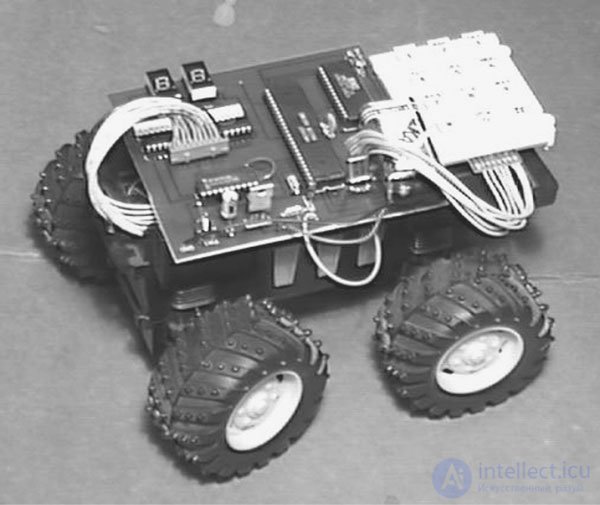
Fig. 7.7. Модель автомобиля с голосовым управлением
Последняя версия упрощает построение интерфейса для УРР. Для удобства соединения в плате имеются 9 монтажных пистонов (8 отверстий под 2 полубайта двоично-десятичного кода и отверстие под землю), которые соединены с выходом ИС 74LS373, расположенной на плате. Старший полубайт выхода 74LS373 управляет работой ИС 4028. Запускающий сигнал можно снимать с выводов красного светодиода.
В дополнение к изменениям схемы интерфейса на плате имеется вход 3. В для обновления памяти. Такое включение делает статическую ОП энергонезависимой. Иными словами, вы можете подавать или снимать питание с платы без потери информации о ключевых словах, записанной в ОП. В оригинальной версии выключение питания приводило к потере информации, записанной в ОП.
Проект 3: общая схема интерфейса УРР
Интерфейс УРР для робота-передвижки является специализированной схемой, предназначенной для конкретной цели. Следующая схема интерфейса (см. рис. 7.8) представляет собой более универсальное устройство, дающее возможность управлять целым набором устройств, таких как роботы, электрические схемы и приборы.
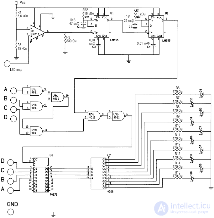
Fig. 7.8. Общая схема интерфейса для УРР
Для того чтобы сильно не усложнять схему и в то же время повысить надежность и точность распознавания системы УРР, мы снова ограничимся списком из 10 управляющих команд. Если вы хотите расширить этот список до полных 40 команд, то можете спроектировать интерфейс на основе идей, изложенных в этой главе. Использование 10 ключей управления позволяет нам использовать для каждого ключа 4 возможных варианта распознавания, как мы уже делали выше. Каждый из четырех вариантов распознавания, связанный с ключевым словом, позволяет запоминать различные варианты произнесения ключевого слова. Понятно, что четыре варианта произношения для каждого ключевого управляющего слова позволят повысить надежность и точность распознавания УРР.
Мы будем нумеровать места команд, как мы это делали выше, поэтому все места, соответствующие одному и тому же ключевому слову, будут иметь соответственно одинаковый младший десятичный разряд. Принцип записи будет ясен из примера.
Предположим, что мы проектируем электрическое кресло-каталку с голосовым управлением. Для управления движением кресла мы будем использовать следующий список команд:
• Вперед
• Назад
• Направо
• Налево
• Стоп
• Выключить
• Включить
• Блокировать
• Разблокировать
• Стоп (Команда «стоп» является жизненно важной, поэтому требует дублирования)
Первой командой для обучения распознавания УРР является «вперед». Мы будем использовать номера ячеек 10, 20, 30 и 40. При исключении старшего десятичного разряда в каждом номере мы получим одинаковое значение младшего десятичного разряда, равное 0. Точно так же команда «назад» записывается в ячейки 01, 11, 21 и 31. После исключения старшего десятичного разряда мы получим номер команды равный 1.
Интерфейс должен опознавать коды ошибок и не смешивать их с командами под номерами 5, 6 и 7. Для этого используется схема, состоящая из двух ИС И-НЕ типа 4011, включенных по схеме логических И и ИЛИ (как показано на рис. 7.8), которая обнаруживает коды ошибок 55, 66 и 77.
Соединение с платой УРР
Плата УРР имеет 9 отверстий под пайку, соединяющих ИС 74LS373 и 7448 для подключения схемы интерфейса (см. рис. 7.8). Восемь шин представляют 2 четырехбитных двоично-десятичных кода, девятая шина – земляная. Имеется контактная площадка красного светодиода. К этой площадке припаивается проводник, который является запускающим входом платы интерфейса.
Принцип работы устройства
Прежде всего интерфейс должен реагировать на любое слово, воспринятое УРР. Когда УРР «слышит» слово, оно пытается его распознать, что вызывает немедленное мигание светодиода.
Ток через светодиод используется для запуска интерфейса (реакция на слово). Для формирования импульса запуска используется компаратор, подключенный к катоду светодиода. Опорное напряжение составляет 3,64 В и формируется резистивным делителем 5,6 кОм и 15 кОм.
Выход компаратора имеет нормально высокий уровень. При поступлении импульса амплитудой 4,5 В с катода светодиода, на выходе компаратора формируется отрицательный импульс запуска. В качестве компаратора использован ОУ типа 741.
Процесс распознавания речи занимает до 300 мс. Во время этой задержки состояние двоично-десятичных выходов сохраняется неизменным. Если интерфейс работает слишком быстро, то он завершит обновление информации на выходе до появления входной информации, содержащейся в двоично-десятичных кодах.
Для предотвращения этого явления мы обеспечиваем задержку отрицательного импульса запуска, используя две ИС таймеров типа 555 (или одну ИС типа 556), включенных по схеме одновибратора. Отрицательный импульс с выхода компаратора запускает первый одновибратор, который выдает импульс длиной 470 мс, подаваемый на вход второго одновибратора. Второй одновибратор генерирует импульс длиной 220 мс.
Импульс длиной 470 мс предоставляет более чем достаточно времени для обновления выходов двоично-десятичного кода. Задний отрицательный фронт этого импульса запускает второй одновибратор, который выдает положительный импульс продолжительностью 220 мс. В это время происходит обновление выходов интерфейса при условии, что детектор кодов ошибок имеет высокий логический уровень на выходе.
Выход второго одновибратора (импульс 220 мс) соединен с одним из входов логического элемента И. Другой вход соединен с двумя другими логическими элементами (ИЛИ-НЕ и ИЛИ), которые образуют детектор кодов ошибок. Детектор кода ошибок соединен со старшим полубайтом двоично-десятичного кода. При наличии кода, соответствующего цифрам 5, 6 или 7 на входе детектора, он выдает низкий логический уровень на выходе. Для остальных цифр детектор имеет высокий выходной уровень. В этом случае позитивный импульс с выхода второго одновибратора запускает интерфейс для принятия младшего полубайта двоично-десятичного кода.
Высокий логический уровень на выходе детектора кода ошибок в комбинации с положительным импульсом с выхода второго одновибратора вызывает появление высокого уровня на выходе логического элемента И, что разблокирует ИС 74LS373. Когда ИС 74LS373 разблокирована, то код, содержащийся в младшем полубайте двоично-десятичного кода, поступает с ИС и записывается в ней. Четыре выхода ИС 74LS373 соединены с входами двоично-десятичного дешифратора 4028.
С другой стороны, если на выходе детектора кода ошибок присутствует сигнал низкого уровня, что происходит при наличии цифр 5, 6 или 7 в старшем разряде, то соответствующий выход элемента И имеет низкий уровень. В этом случае, при наличии положительного импульса от второго одновибратора на втором выводе логического элемента И, его выход по-прежнему имеет логически низкий уровень, тем самым ИС 74S373 блокируется, и информация младшего разряда не поступает на дешифратор 4028.
Таким путем, детектор кода ошибок отделяет числа 55, 66 и 77 от команд под номерами 5, 6 и 7.
При прохождении двоично-десятичного кода через ИС 74LS373, он поступает на вход дешифратора 4028. Дешифратор считывает данный код и выдает сигнал высокого уровня на соответствующей шине выхода (с номерами от 0 до 9).
Усовершенствование выхода интерфейса
Выходы высокого логического уровня ИС 4028 можно использовать для управления нагрузками переменного и постоянного тока. Однако лучшим вариантом является подключение выходов 4028 к триггерам. Дело в том, что в конкретный момент на выходе ИС 4028 присутствует единственный сигнал высокого уровня. По этой причине если в какой-то момент один из выходов включается, то сигнал на выходе, задействованном до того, пропадает, что представляет определенное неудобство. Наличие триггера позволяет решить эту проблему. При первом включении на выходе триггера появится сигнал высокого уровня, который сохранится до подачи на него следующего импульса. Такая схема позволит осуществлять двойное управление (включение и выключение) с помощью одной команды.
Первоначально имеется возможность активировать любое количество выходов без риска сброса уже включенных. Затем та же самая команда может быть использована для включения нагрузки (при первом произнесении) и затем ее выключения (при следующем произнесении). Таким образом, вместо использования пары команд для включения/выключения устройства (например: включить свет/выключить свет) возможно использование единственной команды, которая в «четный» раз выключает устройство (свет-свет). В некоторых случаях это позволяет удвоить список допустимых команд.
In fig. 7.9 показана схема триггера на ИС 4013. Каждая ИС содержит два триггера. Входы триггеров соединены непосредственно с выходами ИС 4028.
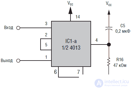
Fig. 7.9.Half trigger 4013 for storing a signal. It is connected directly to the output of the IC 4028, shown in Fig. 7.8, and is intended to save the enabled state of the circuit when the following command is enabled.
In fig.7.10 shows one scheme and two fragments of the connection schemes to the output of the trigger for controlling various types of loads. Part A depicts a Darlington NPN transistor controlling a resistive load in a DC circuit. A similar circuit can be used to control an electromagnetic relay, as shown in B. Relay, respectively, can control DC or AC circuits. In part C, output 4013 is connected to an optocoupler controlling a triac.
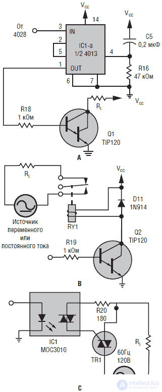
Fig. 7.10. Данные схемы могут быть подключены к интерфейсу, чтобы обеспечить управление схем с помощью УРР. В схеме на позиции А в качестве ключа используется триггер, управляющий Darlington транзистором. В позиции В транзистор заменен реле, что позволяет управлять сильноточными резистивными или индуктивными нагрузками постоянного и переменного тока. Схема на позиции С, объединенная с триггером позиции А позволяет осуществить гальваническую развязку между силовыми и управляющими цепями, управляя при этом включением нагрузки переменного тока
Device operation
The OAI scheme is initially “trained” as described above. After connecting to the interface, any command will cause the LED to light up or some device reaction depending on what is connected to the outputs of the 4028 binary decimal decoder.
Improving the recognition process
There is a set of techniques for improving and optimizing the recognition process. First of all, it is the choice of word commands. Avoid homonyms and similarly sounding words, for example, such as sleep, take, stand, lay. To optimize recognition, use as many different words as possible. In many cases, it is useful to use synonyms or words that have approximately the same meaning. For example, instead of the word “sleep” use “doze” or “fall asleep”. Instead of taking, use grab or raise. Instead of "stand up" - "rise." The word "put" can be replaced by "put". Small philological studies will help to cope with this problem.
Setup and pairing equipment
Distance. The distance from the speaker's mouth to the microphone should be the same when “learning” the system and its operation.
Stress. Under the influence of stress or excitement voice changes. For example, if you use a voice-controlled joystick to control the flight of your favorite military aircraft simulator, then at the time of a hot air battle, your voice shouts out commands “Fire! The fire! Roll to the left! ”Will be slightly different from the voice in a situation where you sit quietly at the table and program OUR. For this reason, during the process of programming sound commands, you must simulate the state of stress or arousal that you feel during the game.
Strenuous effort. Physical stress is another factor. When you program training equipment (a treadmill or bicycle trainer) to control your voice, you must imitate people with a little breathing difficulty.
Ambient noise Ambient noise is always a problem. As noted above, a constant noise (for example, from an air conditioner) has less effect than random noise (operating television).
Robotic arm controlled by OAI
In ch. 15, another interface variant controlling the hand of the robot will be considered.
List of parts for OAI
• (1) IS1 HM2007
• (1) IS2 SRAM 8K x 8
• (1) IS3 74LS373
• (2) IS4 and IS5 7448
• (1) 3.37 MHz quartz resonator
• (1) PCB OUR
• (1) 12-key keyboard
• (2) 7 segment indicator
• (2) assembly of resistors 220 Ohm, 0.25 W, 16 pins
• (1) 22 kΩ 0.25 W resistor
• (1) 5.6 kΩ 0.25 W resistor
• (1) 0.047 microfarad capacitor
• (1) C2 capacitor 100 μF 16 V
• (1) C5 0.1 μF capacitor
• (1) voltage regulator 7805
• (1) microphone
• (1) battery clamp 9V
• full set of parts OUR
Interface Details List
• (2) IC 4011 2 elements OR NOT
• (1) IS 74LS373 8 D Triggers
• (1) IC 4028 Binary Decimal Decoder
• (1) IC timer 555
• (1) OC LM741
• (1) 5.6 kΩ resistor
• (1) 15 kΩ resistor
• (1) 330 ohm resistor
• (2) 10 kΩ resistor
• (10) 470 ohm resistor
• (1) 47 μF capacitor
• (1) 22 μF capacitor
• (2) 0.01 μF capacitor
• (10) LED miniature
• Optional: IC 4013 2 D-flip-flop, transistor TIP 120 NPN Darlington

Comments
To leave a comment
Robotics
Terms: Robotics