Lecture
In this chapter we will try to make an android or humanoid hand. To actuate the fingers of this hand, we will use the air muscles described in ch. 3
The air muscle is a pneumatic device that can contract linearly with compressed air. When activated, this muscle contracts like a living biological muscle. You may think that this work can be successfully performed by pneumatic cylinders, which are currently in wide use. This is true, but air muscles in a certain sense are a boon and a boon for amateur designers and robot makers, since its cost is much lower, it is extremely light, flexible and easy to use.
Aerial muscle has a ratio of developed power to its own weight of about 400: 1. Since most parts of the muscle are made of rubber or plastic, it can work in humid conditions or even under water. The air muscle is a flexible structure that allows it to be used to connect and compress coaxial or non-axial blocks and levers. The air muscle is able to contract, even if it is bent along a curved surface. The ease of use of the muscle makes it preferable to conventional pneumatic cylinders in a number of experiments.
Of course, as with any pneumatic device, compressed air is required to work the muscles. Compressed air is not as affordable as electric current. When I first decided to try to make an air muscle, I thought that creating a small device that produces compressed air could be a problem. As it turned out, I was wrong. A simple air system can be made by spending only $ 25.00, and a small electric pneumatic system will cost $ 50.00.
When using electricity to compress air, the total efficiency of the device drops. However, the air muscle consumes a very small amount of air to work, so you can create a tank for storing it. The muscle responds very quickly to the air supply and has a short working cycle. A small muscle weighing only 10 g is able to lift a weight of about 6.5 kg.
Before we start making the android arm, we will first make several hand-operated demonstration devices using air muscle. Demonstration devices will allow us to become more familiar with the device and the work of the air muscle, before we begin a more complex project.
If the device uses one or two muscles, they can be easily controlled "manually." If there are five or six air muscles, then for their sequential or simultaneous activation, “manual” control becomes difficult. In this case, we use computer control. You can use an IBM PC or a suitable PIC microcontroller. The interface scheme for any computer remains unchanged. In this chapter, we will use the IBM PC. Controlling the air muscle using a computer (IBM printer port or compatible) via a parallel PC port will add approximately $ 25.00 to the cost of the air muscle design.
The benefits of air muscle
• Low weight. Air muscle 150 mm long with an air supply tube 4 mm in diameter and 450 mm long weighs approximately 10 g.
• Reduction. Air muscle 150 mm long is reduced by about 25 mm (about 25% without taking into account the length of the mounts).
• Power. Develops a force of about 200 g at an air pressure of 3 kgf. The ratio of developed power to weight can reach 400: 1.
• Flexibility. Soft and flexible design that can be bent along a curved surface without compromising its performance.
Application
The design of the air muscle itself makes it particularly suitable for use in robotics and automated motion systems. In some cases, they can be replaced by servomotors or DC motors. Their unique properties - low weight, power and flexibility - can be comprehensively used in many applications and used to improve the performance of existing pneumatic devices. In a word, air muscles can be used in many devices that require linear and contractile movements. In many cases, they can successfully replace pneumatic cylinders.
How the air muscle works
Air muscle is a long tube, made in the form of a black plastic sleeve. A soft rubber tube is placed inside the sleeve. Metal clips are attached to each end. Each end of the plastic sleeve is folded into a loop, folded in half and sealed with a metal clip. These loops are used to attach the air muscle to other parts of the device.
When air is supplied under pressure, the muscle contracts as follows. When compressed air is supplied to the internal soft rubber tube, it expands. The inner tube puts pressure on the outer black plastic sleeve, which also leads to its expansion. When a plastic sleeve expands, it shortens in length in proportion to the increase in its diameter. This leads to a reduction in the structure of the air muscle. However, it is important that in order for the muscles to work properly, it must be in an extended position when it is not activated. Otherwise, when muscle is activated, we will not get its contractions (see Fig. 16.1).
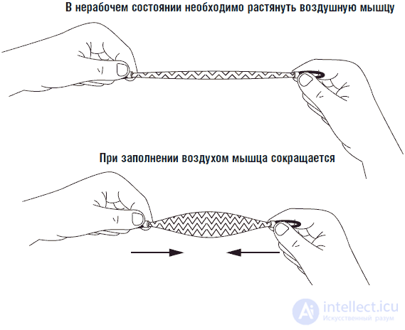
Fig. 16.1 The principle of the air muscles
Details of the air muscle system
In fig. 16.2 shows the details of the parts needed to create an air muscle. Detail 1 is the air muscle itself (which is obvious). Detail 2 - air valve for three positions. The three-position air valve allows you to control the muscle work manually (see. Fig. 16.3).
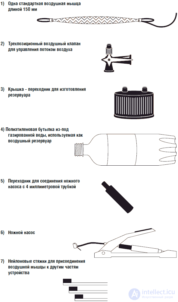
Fig. 16.2. Necessary parts for experiments with air muscle
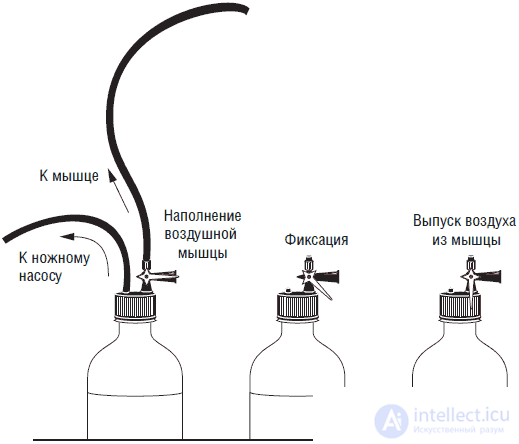
Fig. 16.3. Three-position air valve for controlling air muscle
Item 3 is a bottle cap adapter with a safety valve (the valve opens at a pressure of more than 4.2 kgf). The bottle cap adapter allows the use of standard polyethylene carbonated water bottles as air tanks. The safety valve automatically bleeds off excess air when the pressure exceeds a predetermined limit.
Part 4 is a polyethylene carbonated water bottle used as an air tank. The plastic bottle easily maintains pressure of 3,5 kgfs. I checked similar sparkling water bottles with static pressure up to 7 kgf. Warning: Never use glass bottles as an air tank. A small crack in the bottle or its accidental fall can lead to an explosion of the bottle, accompanied by the scattering of glass fragments. Pumping a plastic bottle can only inflate it.
Part 5 is a foot pump adapter, and part 6 is the air pump itself. A conventional foot pump with a pressure gauge is able to create pressure in a bottle up to 7 kgf. Due to the small capacity of plastic bottles, a pressure of 3.5 kgf is achieved in them after four “strokes” of the foot pump. Air muscle uses a very small amount of air, so a small plastic bottle contains enough air for four or five complete cycles of operation. Item 7 is a nylon cable tie, which is used to quickly tie the air muscle to other mechanical parts.
In fig. 16.4 shows a general view of the entire system assembly. In some cases, you will have to use epoxy glue to glue some parts together to prevent them from “popping out” under pressure. For example, if you intend to use a three-position air valve for experiments with air muscle exclusively in conjunction with a bottle cap adapter, you can permanently glue the valve into the adapter.
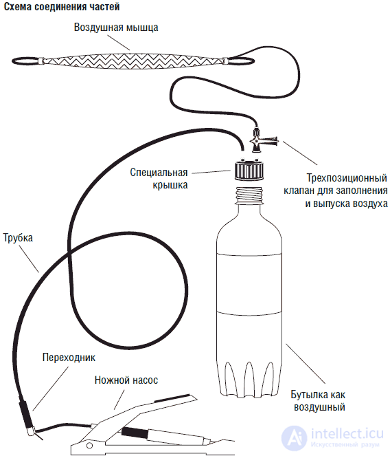
Fig. 16.4. General wiring diagram of the parts of the installation
Air muscle attachment to other mechanisms
The air muscle is made of a soft inner tube encased in a durable plastic sleeve. The design is fastened with metal clips on each side. The ends of the plastic sleeve are bent into a loop having a hole. A loop with a hole has great mechanical strength and can be used to connect the air muscle with other mechanisms. In fig. 16.5 shows a screw inserted in a loop hole.
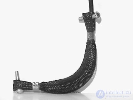
Fig. 16.5. The screw passes through one of the loops of the air muscle
Using an air pump adapter
The air pump you purchased has a standard nozzle (nozzle), as shown in fig. 16.6. We will need to replace the standard spout with a special adapter. Raise the locking lever as shown in fig. 16.7. Remove the standard spout (see fig. 16.8) and insert the air adapter (see fig. 16.9). Close the locking lever by pushing it down.
Fig. 16.6. Foot pump nozzle
Fig. 16.7. Raise the locking lever (above the foot pump nozzle)
Fig. 16.8. Remove the standard nozzle adapter
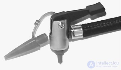
Fig. 16.9. Insert the adapter into the foot pump
Do you have Coca Cola or Pepsi Cola?
You will need to get a plastic polyethylene bottle. The easiest way is to buy a bottle of sparkling water. Make sure the bottle is made of plastic. Do not buy a bottle of more than 1 liter. The ideal bottle is 0.5 liters. I tried to screw the adapter on the bottles of different containers up to 2 liters, and he went to all.
Use the contents of the bottle, and then wash the bottle with warm water. The bottle must be completely dry before use. An interesting fact is that if you accidentally drop a full bottle of carbonated water, the resulting pressure of carbon dioxide released from sodium carbonate will significantly exceed 3.5 kgf - the limit we set for such bottles. Carbonated companies produce plastic bottles in such a way that they can withstand the rapid increase in gas pressure that occurs when the bottle accidentally drops. I did not realize this fact before I started working with the air muscles, and I think that I would never have known it. Remember that in the design of the air muscles can not use glass bottles.
Making the first demonstration device
The first demonstration device that we are going to make is very simple in design and can be used to measure the degree of contraction of the air muscle (see. Fig. 16.10). The base is a plank 25x 50x 275 mm thick. I used similar material because it can be found everywhere. You might as well use metal or plastic. At each of the ends, I drilled a hole for screws of 3 millimeters in length of 45 mm. The screws are inserted into the hole and secured with two 3 mm nuts, one on each side of the plank. The screw head and part of the thread protrude about 20 mm above the plank.
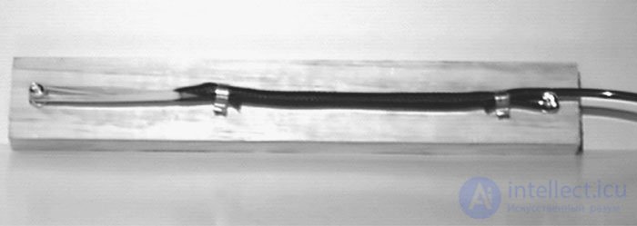
Fig. 16.10. First demo model
Before installing the head of the upper screw must be threaded into the hole of the upper loop of the air muscle. A piece of rubber band is passed through the hole in the lower loop of the air muscle, which is then fastened to the bottom screw. In the free state of the muscle rubber band should stretch it.
Make the necessary connections of the parts, as shown in fig. 16.4. In some cases, I had difficulty putting the 4 mm tube on the nipples. There are several tricks here. First, if the tube does not want to be put on the adapter, then you can place it under a stream of hot water from a water tap. This will soften the plastic and allow you to perform the operation. You can also use a piece of clear plastic medical tube. The plastic tube fits tightly enough over the adapter nipples (see fig. 16.11). On the other hand, it is sufficiently stretchable so that a tube with a diameter of 4 mm can be inserted into it (see Fig. 16.12). A piece of soft tube acts as an adapter and can easily be disengaged when changing devices using air muscles.

Fig. 16.11. Using a transparent medical tube with standard adapters
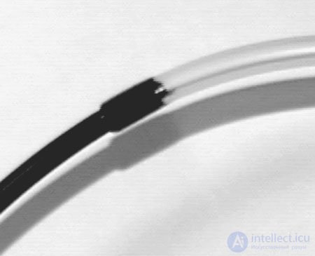
Fig. 16.12. Connection of a transparent tube and a tube of 4 mm
To make the device work, first create overpressure with a foot pump. To raise the pressure to 3.5 kgf, four taps are enough. The operating time with the pump depends on the capacity of the used polyethylene bottle.
Open the three-way valve to fill the muscle with air. The muscle will immediately contract. You can determine the ratio of muscle contraction depending on the amount of excess pressure applied. You will be able to complete four or five complete cycles of contraction - muscle relaxation, before you again need to fill the bottle with air. Indeed, the muscle at work consumes a very small amount of air.
Note that the air muscle remains in a contracted state until the vent valve is turned to release air. To maintain the muscles in the contracted state does not require energy. In contrast, to ensure that the solenoid is pulled in or out and the servomotor positioned, they must be constantly supplied with electrical energy.
If the muscle is not contracting, then it may not have been stretched enough in the initial state. Remember that the normal work of the air muscle is ensured only with its preliminary stretching.
Making a second demonstration device
The second model is a lever (see fig. 16.13 and 16.14). I made a model of the lever of wood and plastic. The air muscle and the rubber band are attached to the lever with screws. At the pivot point the lever is fixed on a wooden pin. On the second wooden pin fasten the air muscle and rubber band. The device works with the help of a three-position valve, which I have already mentioned above. When air is applied, the lever rises.
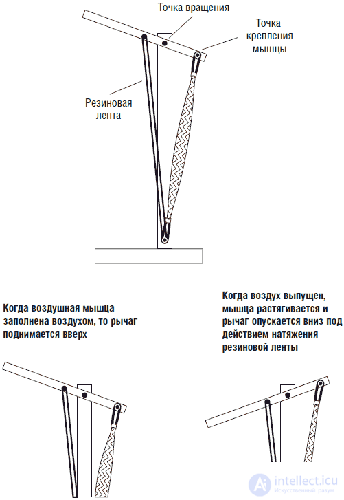
Fig. 16.13. The second demonstration model "lever"
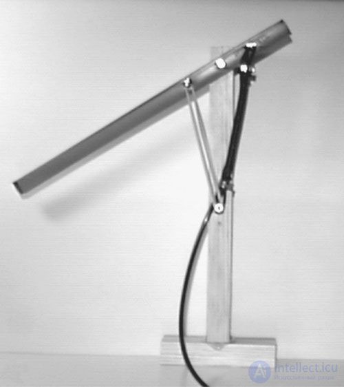
Fig. 16.14. The second demonstration model "lever"
IBM interface
Computer control is very simple. The computer controls the electric three-position valve. Cheap three-position, electrically operated solenoid-operated air valves are commercially available (see Fig. 16.15). The air valve is controlled by a constant voltage of 5 V and is designed for pressures up to 6.3 kgf. The air valve has easily attachable and disconnectable air "connectors". A 4 mm tube easily enters the valve orifice and is securely fixed there. To disconnect the tube, press with your fingers on the ring around the valve opening, and then remove the tube with a diameter of 4 mm.
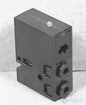
Fig. 16.15. Electric three-position air valve
To control one air valve, it suffices to use one pin on the parallel port connector (printer port) and ground pin (see. Fig. 16.16). The output is connected via a logical element - a non-inverted buffer circuit on the IC 4050HCT. The output of the buffer controls the transistor switch on the TIP 120 NPN Darlington transistor. The transistor controls the current flowing through the air valve.
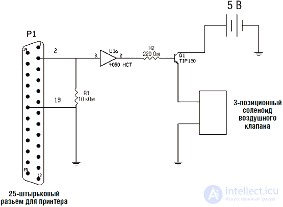
Fig. 16.16. Schematic diagram of the controller of the air valve
Program at BASIC
The program at BASIC is very simple. After finding the address of the port of the printer, the program controls the operation of the air valve through pin 2.
5 REM Air Valve Solenoid Controller
10 REM John Jovin
15 REM Find printer port address
20 DEF SEG = 0
25 a = (PEEK (1032) + 256 * PEEK (1033))
30 REM The next line includes the air muscle.
35OUT a, 1
40 REM The next line turns off the air muscle.
45 OUT a, 0
With a high signal level at pin 2 DB 25, the air valve opens and air is blown into the air muscle. When the signal level at terminal 2 is low, air is forced into the air muscle and the valve releases air from the muscle.
Other air sources
I In the air muscle, which we have described, as a source of contraction
In addition, an air pump and a plastic bottle were used as an air reservoir. It is clear that compressed air from any available source can be used. For example, you can purchase small cans of compressed air used in spray guns. The small tubes and fittings that are available in the kits of these dispensers will help you in your experiments.
There are several models of small electric air compressors on the market.More expensive models used in paint sprayers have metal air storage tanks and pressure regulators. At the other end of the price scale are cheap portable air compressors operating from 12 V DC and used to inflate tires. In such compressors, as a rule, there is no air tank and pressure regulator. These compressors can be purchased to create an inexpensive pneumatic system.
For automatic air compressor systems, never use plastic bottles. Such bottles can be used to store air exclusively in systems of manual (or foot) compressors (pumps). In automatic air compression systems, use only special containers designed for storing compressed air. Small containers are quite inexpensive.
Safety first
Pneumatic systems are used relatively rarely in everyday life, so only a few know how to properly handle such devices. For this reason, when working with pneumatic systems it is necessary to adhere to certain safety regulations.
When testing a new device, always wear safety glasses.
Do not attach a plastic bottle to an automatic compressor.
Do not use glass bottles for air storage.
Do not use bottles with a capacity of more than 1 liter as tanks.
Do not unscrew the bottle cap, remove the valve or remove the tubes from the nozzles when the system is under pressure. Before performing these operations, be sure to relieve the pressure in the system.
Android Hand
The design of the capture mechanism, reminiscent of the human hand, begins with a visit to the toy store. We need a toy called Awesome Arm, manufactured by the Chinese company Zima (see fig. 16.17). In order for you to have enough "fingers", you need to buy two such toys. The thumb of the toy has a fixed position and cannot be used.
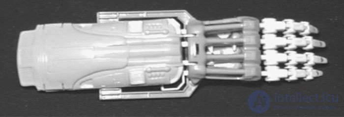
Fig.16.17. Zima's Awesome Mechanical Arm
The toy works as follows: the “fingers” of the toy are actuated by the operator’s fingers, i.e. the toy is a kind of remote manipulator. To make an android hand, we have to disassemble the toys and remove most of the details from them.
When you turn your hand, you will see five small screws that hold the structure together. Remove these screws, and the design will fall apart (see. Fig. 16.18). Remove the "finger" part of the toy (see fig. 16.19). We will not need the rest of the toy. At the end of the rods, which control the "fingers", there are "rings" where the operator inserts the fingers when controlling the toy. We do not need these rings, so it is necessary to remove them with pliers, leaving a long plastic rod.
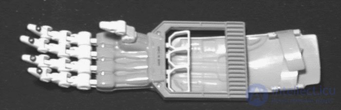
Fig.16.18. Reverse side of the arm where it is necessary to unscrew the mounting screws
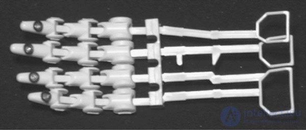
Fig.16.19. Hand drawn fingers
Details of the design are collected on the board. I began by tracing the outline of the brush of my right hand on paper. Then I blackened some inside of the picture (see fig. 16.20). Along the contours of the blackened pattern, I cut a plate of aluminum 3 mm thick.
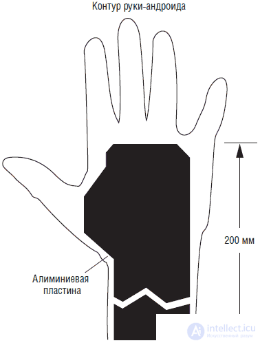
Fig.16.20. The contour of the hand and the position of the aluminum base
Fingers are attached to the end of the board. First mark the position of the fingers on the board. Then place a small aluminum plate with a width of 12 mm and a thickness of 3 mm immediately behind the plastic fastening of the fingers (see. Fig. 16.21). This plate is a back rest for attaching fingers. Drill three holes through the plate and the base and fix the plate to the base with screws and nuts. Secure the 3x12mm aluminum plate over the plastic base of the fingers. Drill four holes in the plate and the board, as shown in fig. 16.22. The design is fastened with screws, 25 mm long and nuts. These screws have a dual purpose. First, they fasten the base of the fingers and hold the fingers in the design. Secondly, a rubber band will be attached to them, providing stretching of the air muscles.
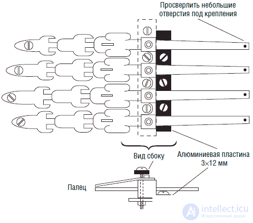
Fig. 16.21. Крепление задней пластинки
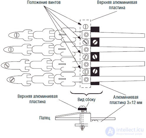
Fig. 16.22. Крепление верхней пластинки
После того как пальцы закреплены на плате, нам необходимо прикрепить к каждому пальцу воздушную мышцу. Напомню, что для правильного сокращения воздушной мышцы она должна быть предварительно растянута. Проденьте резиновую петлю через конец воздушной мышцы. Затем отверните и выньте первый из четырех винтов длиной 25 мм, которые крепят основание пальцев. Просуньте сложенные концы резиновой петли в то место, где винт проходит через верхнюю пластинку. Вставьте винт на место, продев через него концы резиновой петли, и затем затяните с помощью гайки (см. рис. 16.23 и 16.24).
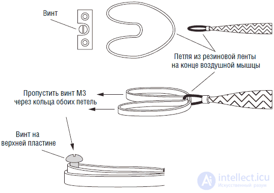
Fig. 16.23. Продеть сложенную резиновую ленту через один конец воздушной мышцы и закрепить концы ленты на винте крепления верхней пластинки
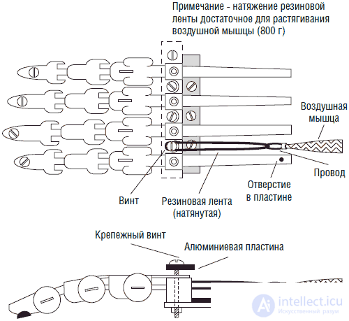
Fig. 16.24. Общий вид крепления воздушной мышцы к тяге пальца
Потяните воздушную мышцу за другой конец до того, как она будет полностью растянута. Заметьте положение конца воздушной мышцы. В этом месте просверлите отверстие в плате и вставьте туда винт, закрепленный с помощью гаек. Для поддержания воздушной мышцы в растянутом состоянии наденьте конечную петлю воздушной мышцы на винт (см. рис. 16.25).
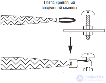
Fig. 16.25. Крепление заднего конца воздушной мышцы к крепежному винту для ее растяжки
Теперь просверлите небольшое отверстие в пластиковой части тяги пальца. Положение отверстия должно соответствовать положению передней петли крепления воздушной мышцы. Отверстие должно быть достаточно велико, чтобы в него проходил сложенный вдвое многожильный провод. Можно использовать оголенный одножильный медный провод 0,6 мм или многожильный стальной. Пропустите сложенный вдвое многожильный провод через отверстие в пластике и через отверстие петли переднего крепления мышцы. Скрепите детали путем скручивания концов провода. Если концы скрученного провода окажутся слишком длинными, то удалите излишки с помощью кусачек.
Примерный вид сверху показан на рис. 16.24. Теперь мы можем увидеть, каким образом будут сокращаться пальцы. Пальцы сокращаются при подаче сжатого воздуха в воздушную мышцу. Сократившаяся мышца воздействует на пластиковую тягу, управляющую пальцем, что в свою очередь вызывает его сокращение. Когда с воздушной мышцы снимается давление, то резиновая лента растягивает ее в первоначальное положение.
Теперь неплохо провести статическое испытание работы пальца. Соедините подачу воздуха с воздушной мышцей, чтобы убедиться в работоспособности устройства. В начальном варианте устройства для полного сгибания указательного пальца требовалось давление порядка 3 кгс.
Когда вы убедитесь, что палец работает правильно, присоедините воздушные мышцы к остальным пальцам таким же образом. In fig. 16.26 показан детальный вид воздушных мышц, соединенных с тягами соответствующих пальцев.
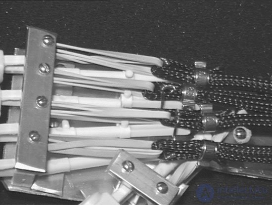
Fig. 16.26. Детальный вид воздушных мышц, резиновых лент и пальцевых тяг в сборе
Большой палец
Большой палец является самым важным при работе кисти. С его помощью сильно облегчается захват, удерживание и использование различных предметов. Вы так не думаете? Попробуйте тогда поднять с пола или со стола монету без помощи большого пальца. А теперь попробуйте поработать с плоскогубцами, кусачками, молотком или дрелью.
Для изготовления большого пальца воспользуйтесь мизинцем из набора второй купленной игрушки. Закрепите этот палец ниже под углом 45° по отношению к другим пальцам (см. рис. 16.27).
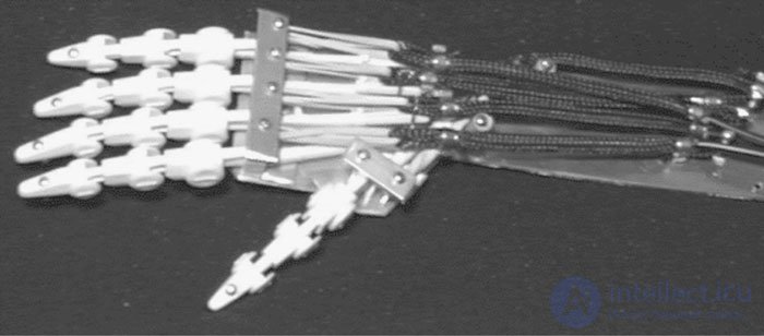
Fig. 16.27. Вид кисти-робота в сборе
В первоначальной конструкции большой палец сгибается в сочленениях (двигается), но не может совершать движений навстречу другим пальцам. Конструкцию можно улучшить, обеспечив встречное движение большого пальца, что увеличит эффективность работы руки. Чтобы обеспечить встречное движение пальца, необходимо отрезать «место» большого пальца на плате и заменить его шарнирным соединением на пружине (см. рис. 16.28). Подпружиненный шарнир может быть расположен на прямоугольной коробочке, показанной на рис. 16.28. Воздушная мышца присоединяется к этой секции: когда мышца активируется, то она тянет большой палец в сторону ладонной части кисти. Таким образом, обеспечивается как сгибательное, так и встречное движение большого пальца.
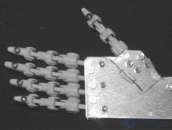
Fig. 16.28. Вариант крепления большого пальца для обеспечения сгибательного и встречного движения
Дальнейшее усовершенствование
Возможно создание устройства интерфейса между кистью руки робота и IBM-совместимым компьютером, в котором используются пять электрических воздушных клапанов, аналогичное устройству с одним клапаном, описанному выше. Чтобы превратить кисть робота в кисть – андроида, можно надеть на кисть сверху соответствующий чехол (см. рис. 16.29).
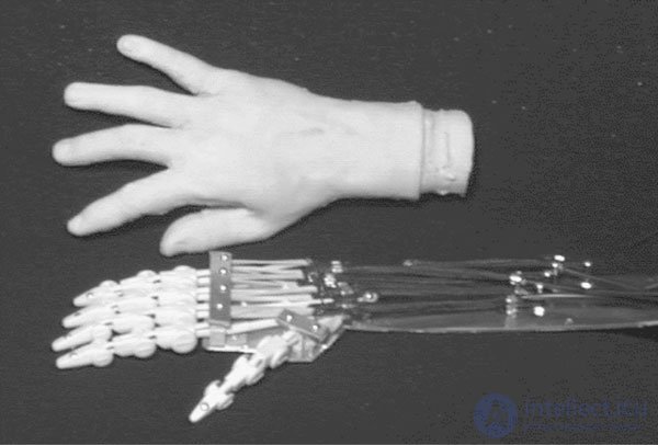
Fig. 16.29. Резиновая перчатка подходящей формы и размера для превращения руки-робота в «андроидную» руку
Отметим еще несколько интересных применений воздушной мышцы:
• Шестиногий робот-ходок
• Зажим для быстрого открывания банок (для людей, страдающих артритом)
• Кисть-робот
• Рука-робот
Список деталей для воздушной мышцы
• (1) Воздушная мышца, длина 150 мм с подводящей трубкой 4 мм
• (1) Крышка полиэтиленовой бутылки с предохранительным клапаном
• (1) Трехпозиционный воздушный клапан
• (1) Переходник для воздушного насоса
• (1) Ножной воздушный насос с максимальным давлением до 7 кгс
• (1) воздушная трубка диаметром 4 мм
• (1) медицинская прозрачная трубка (для быстрой разборки)
Список деталей для интерфейса IBM
• (1) Трехпозиционный электрический воздушный клапан, управляемый соленоидом постоянного тока 5 В, максимальное давление 6,3 кгс
• (1) разъем DB 25
• (1) ИС логический буферный элемент 4050HCT
• (1) Транзистор TIP 120 NPN Darlington

Comments