Lecture
This project is a multi-level modular task. The first stage of the project is the assembly of a robotic arm-manipulator module, supplied as a set of parts. The second stage of the task will be assembling the interface of the IBM PC also from a set of parts. Finally, the third stage of the task is the creation of a voice control module.
The robot manipulator can be controlled manually using the handheld control unit included in the kit. The robot's hand can also be controlled either through an IBM PC interface assembled from a set, or using a voice control module. The IBM PC Interface Kit allows you to control and program robot actions through an IBM PC work computer. The voice control device will allow you to control the robot arm with voice commands.
All of these modules together form a functional device that allows you to conduct experiments and program automated workflows or even “revive” a fully manipulated arm.
The PC interface allows you to program a manipulator arm using a personal computer on a chain of automated actions or “liven up” it. There is also an option in which you can control your hand online, using either a hand controller or a program under Windows 95/98. The “revitalization” of the hand is the “entertainment” part of the chain of programmed automated actions. For example, if you put a baby glove doll on the arm-manipulator and program the device to show a small show, then you will program the “animation” of the electronic doll. Programming automated action is widely used in industry and the entertainment industry.
The most widely used robot in the industry is the robot arm. A robot arm is an exceptionally flexible tool, if only because the end segment of the arm of a hand can be the appropriate tool required for a specific task or production. For example, the articulated welding arm can be used for spot welding, various parts and assemblies can be painted using a spray nozzle, and the grip can be used to clamp and install objects - these are just some examples.
So, as we see, the robot arm performs many useful functions and can serve as an ideal tool for studying various processes. However, creating a robotic arm with a “zero” is a complex task. It is much easier to assemble a hand from the parts of the finished set. OWI sells reasonably good arm sets that can be purchased from many electronic device distributors (see the list of parts at the end of this chapter). Using the interface, you can connect the assembled hand manipulator to the printer port of the work computer. As a working computer, you can use an IBM PC or a compatible PC that supports DOS or Windows 95/98.
Once connected to the printer’s port on a computer, a manipulator can be operated interactively or programmatically from a computer. Handling online is easy. To do this, simply click on one of the function keys to send the robot the command to perform a particular movement. A second keystroke terminates the command.
Programming a chain of automated actions is also not difficult. First click on the Program key to switch to program mode. In this mode, the hand functions in exactly the same way as described above, but in addition, in addition, each function and its time are fixed in the script file. A script file can contain up to 99 different functions, including pauses. The script file itself can be replayed 99 times. Writing various script files allows you to experiment with a computer-controlled sequence of automated actions and “revitalizing” your hand. Working with the program under Windows 95/98 is described in more detail below. The program under Windows is included in the interface set of the robotic arm-manipulator or can be downloaded for free from the Internet http://www.imagesco.com.
In addition to the Windows program, you can control your hand using BASIC or QBASIC. The DOS level program is contained on diskettes included in the interface kit. However, the DOS program allows you to control only interactively using the keyboard (see the printout of the BASIC program on one of the diskettes). The DOS level program does not allow creating script files. However, if there is programming experience on BASIC, then the sequence of hand-arm movements can be programmed in the same way as the script file used in the Windows program. The sequence of movements can be repeated, as is done in many "animated" robots.
Robotic arm
The arm (see Fig. 15.1) has three degrees of freedom of movement. The elbow joint can move vertically up and down along an arc of approximately 135 °. The shoulder "joint" moves the grip back and forth along an arc of approximately 120 °. The hand can be rotated clockwise on the base or counterclockwise at an angle of about 350 °. Grabbing a robot's arm can pick up and hold objects up to 5 cm in diameter and turn around in the wrist joint about 340 °.
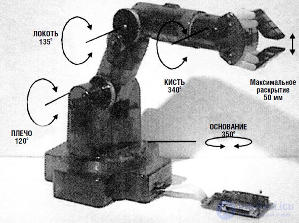
Fig. 15.1. Kinematic diagram of the movements and turns of the arm-robot
The OWI Robotic Arm Trainer used five miniature DC motors to bring the arm in motion. Motors provide hand control with wires. This “wired” control means that each motion function of the robot (i.e., the operation of the corresponding motor) is controlled by separate wires (voltage supply). Each of the five DC motors controls its movement of the arm. Wire control allows you to make a hand controller unit that reacts directly to electrical signals. This simplifies the interface of the robot arm, which connects to the printer port.
Hand made of lightweight plastic. Most of the parts bearing the main load are also made of plastic. The DC motors used in the design of the hand are miniature high-speed engines with low torque. To increase torque, each motor is connected to the gearbox. The motors together with the gearboxes are installed inside the arm-manipulator design. Although the gearbox increases torque, the robot’s hand cannot lift or carry heavy objects. The recommended maximum allowable weight when lifting is 130 g.
The kit for making a robot arm and its components are presented in Figures 15.2 and 15.3.
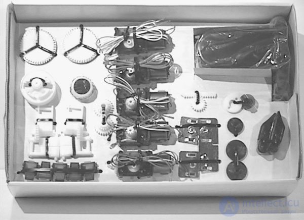
Fig. 15.2. Hand Robot Kit
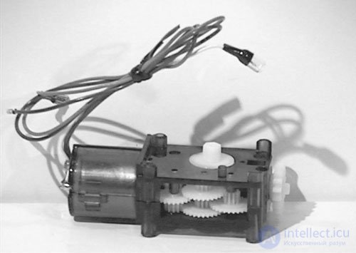
Fig. 15.3. Gearbox before assembly
Motor control principle
In order to understand how the control works by wire, let's see how the digital signal controls the operation of a separate DC motor. Motor control requires two complementary transistors. One transistor has a conductivity of PNP type, the other - respectively, the conductivity of NPN type. Each transistor operates as an electronic key, controlling the movement of the current flowing through the DC motor. The directions of current movement, controlled by each of the transistors, are opposite. The direction of the current determines the direction of rotation of the engine, respectively clockwise or counterclockwise. In fig. 15.4 the test circuit which you can collect before manufacturing of the interface is given. Note that when both transistors are locked, the motor is off. Only one transistor should be turned on at a time. If at some point both transistors are accidentally open, this will lead to a short circuit. Each motor is controlled by two interface transistors operating in a similar way.
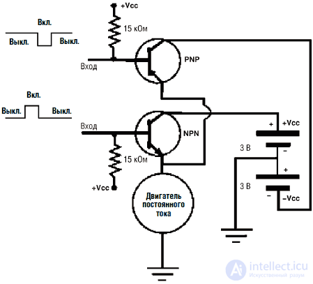
Fig. 15.4. Check device circuit
PC Interface Design
A diagram of the PC interface is shown in Fig. 15.5. The PC interface kit includes a printed circuit board, the location of which is shown in Fig. 15.6.
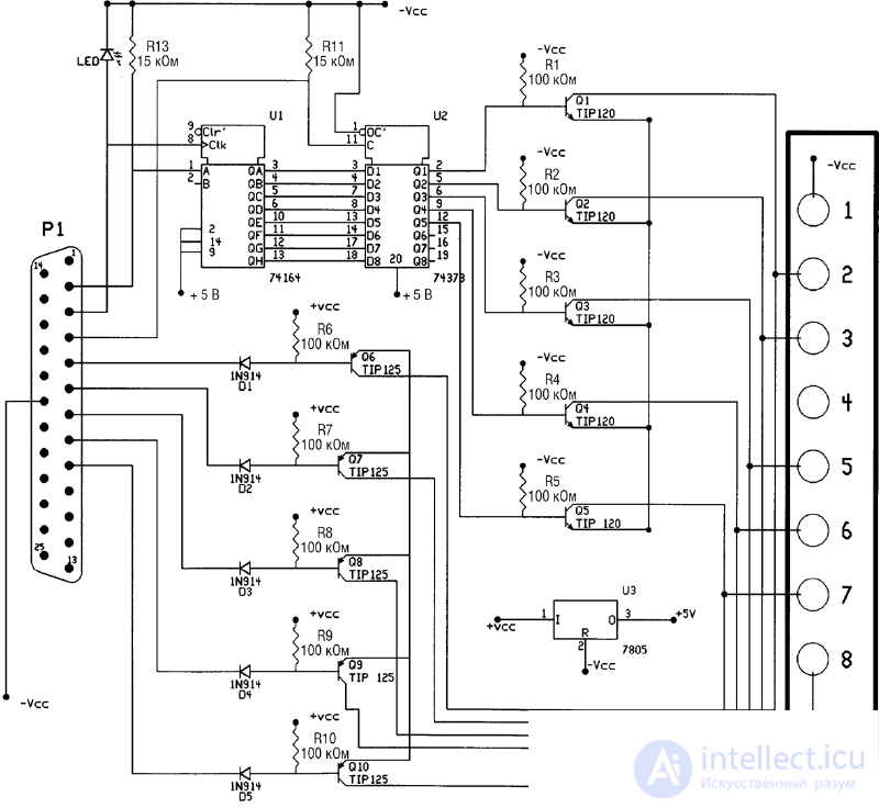
Fig. 15.5. Schematic diagram of the PC interface
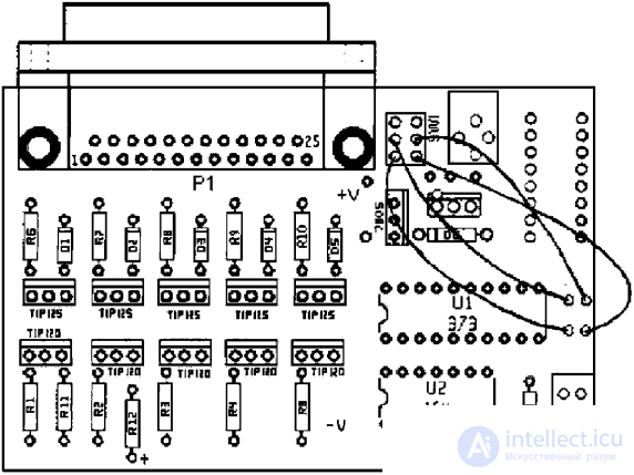
Fig. 15.6. The layout of the details of the PC interface
First of all, you need to determine the direction of installation of the PCB. On the mounting side, white lines are drawn denoting resistors, transistors, diodes, ICs and a DB25 connector. All parts are inserted into the board from the mounting side.
General note: after soldering the part to the conductors of the printed circuit board, it is necessary to remove unnecessarily long leads from the print side. It is very convenient to follow a specific sequence when installing parts. First mount the 100 kΩ resistors (color coded rings: brown, black, yellow, gold or silver), which are labeled R1-R10. Then mount the 5 diodes D1-D5, making sure that the black strip on the diodes is opposite the DB25 connector, as shown by the white lines on the mounting side of the printed circuit board. Then mount the 15 kΩ resistors (color coded, brown, green, orange, gold or silver), labeled R11 and R13. In position R12, solder a red LED to the board. The anode of the LED corresponds to the hole under R12, indicated by the + sign. Then mount the 14– and 20-pin panels under the U1 and U2 ICs. Fit and solder the angle-type DB25 connector. Do not attempt to insert the connector pins into the board with excessive force; only accuracy is required here. If necessary, gently shake the connector, being careful not to bend the legs of the terminals. Fix the slide switch and voltage regulator type 7805. Cut four pieces of wire of the required length and solder to the top of the switch. Adhere to the location of the wires, as shown in the figure. Insert and solder the TIP 120 and TIP 125 transistors. Finally, solder the eight-pole ground connector and 75 mm connecting cable. The plinth is mounted so that the longest conclusions are looking up. Insert two ICs - 74LS373 and 74LS164 - into the corresponding panels. Make sure that the position of the IC key on its cover matches the key marked with white lines on the printed circuit board. You may have noticed that the board has room for additional details. This place is for a network adapter. In fig. 15.7 shows a photograph of the finished interface from the installation side.
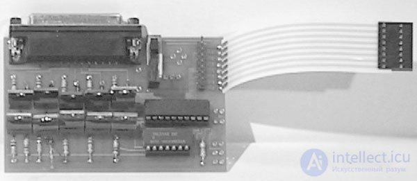
Fig. 15.7. PC interface assembly. View from above
Interface operation principle
The arm has five DC motors. Accordingly, we will need 10 input / output buses to control each engine, including the direction of rotation. The parallel (printer) port of the IBM PC and compatible machines contains only eight I / O buses. To increase the number of control buses in the robot arm interface, the 74LS164 IC is used, which is a serial-to-parallel code converter (SIPO). When using only two buses of the parallel port D0 and D1, through which a serial code is sent to the IC, we can get eight additional I / O buses. As already mentioned, you can create eight I / O buses, but this interface uses five of them.
When the serial code arrives at the input of the IC 74LS164, the corresponding parallel code appears at the output of the IC. If the outputs of the IC 74LS164 were directly connected to the inputs of the control transistors, then the individual functions of the manipulator arm would be turned on and off in time with the sending of the serial code. Obviously, this situation is unacceptable. To avoid this, the second IC 74LS373, a controlled eight-channel dongle, was introduced into the interface circuit.
The IC 74LS373 eight-channel key has eight input and eight output buses. Binary information present on the input buses is transmitted to the corresponding outputs of the IC only if an enabling signal is applied to the IC. After the enabling signal is turned off, the current state of the output buses is saved (remembered). In this state, the signals at the input of the IC have no effect on the state of the output buses.
After transmitting the sequential packet of information to the IC 74LS164 from the D2 pin of the parallel port, the enabling signal to the IC 74LS373 is sent. This allows you to transfer information already in parallel code from the input of the IC 74LS174 to its output buses. The state of the output buses are controlled respectively by the TIP 120 transistors, which, in turn, control the functions of the manipulator arm. The process is repeated when each new command is submitted to a manipulator arm. Parallel port buses D3-D7 directly control TIP 125 transistors.
Connecting the interface to the manipulator arm
The power of the robotic arm-manipulator is supplied from a 6 V power supply consisting of four D-elements located at the base of the structure. The PC interface is also powered by this 6 V source. The power source is bipolar and produces voltages of ± 3 V. Power is supplied to the interface through an eight-pin Molex connector connected to the base of the manipulator.
Attach the interface to the manipulator arm using an 75 mm Molex eight-wire cable. The Molex cable connects to the connector located at the base of the manipulator (see fig. 15.8). Check the correct and reliable insertion of the connector. To connect the interface board with a computer, use a DB25 type cable with a length of 180 cm, available in the kit. One end of the cable connects to the printer port. The other end is connected to the DB25 connector on the interface board.
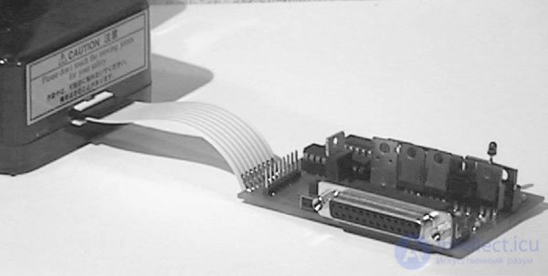
Fig. 15.8. PC interface connection with a robot arm
In most cases, a printer is regularly connected to the printer port. In order not to engage in connecting and disconnecting connectors each time you want to use a manipulator, it is useful to purchase a two-position A / B printer switch busbar unit (DB25). Connect the keypad interface to input A, and the printer to input B. You can now use the switch to connect the computer to either the printer or the interface.
Installing the program under Windows 95
Insert a 3.5 "diskette with the label" Disc 1 "into the floppy disk drive and run the installation program (setup.exe). The installation program will create a directory named" Images "on the hard disk and copy the necessary files to this directory. In Start The Images icon will appear in the menu. To start the program, click on the Images icon in the start menu.
Work with the program under Windows 95
Connect the interface to the computer's printer port using a DB 25 cable 180 cm long. Connect the interface to the base of the manipulator arm. Until a certain time, keep the interface off. If the interface is turned on at this time, the information stored in the printer port may cause movements of the manipulator arm.
Double-click the Images icon in the start menu to start the program. The program window is shown in Fig. 15.9. When the program is running, the red LED on the interface board should flash. Note: for the LED to start flashing, power on the interface is not required. The speed of the LED blinking is determined by the speed of your computer's processor. LED flickering can be very dim; in order to notice this, you may have to reduce the illumination in the room and fold your palms with a “ring” to observe the LED. If the LED is not blinking, then the program may be accessing the wrong port address (LPT port). To switch the interface to another port address (LPT port), go to the window of the Printer Port Options box in the upper right corner of the screen. Select another option. Correctly setting the port address will cause the LED to flash.
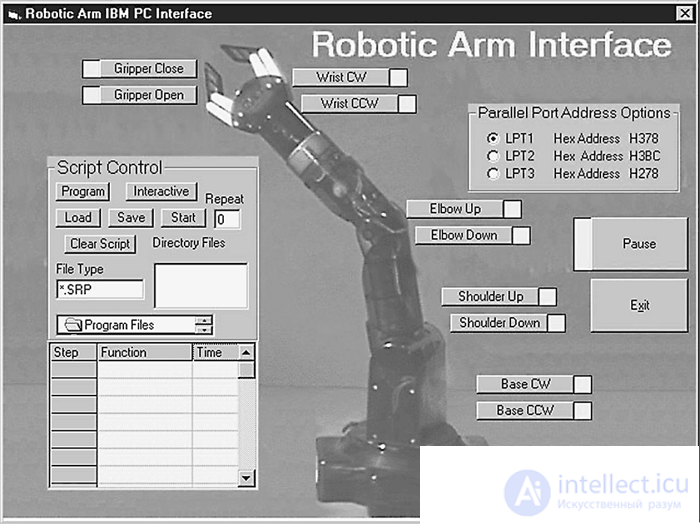
Fig. 15.9. Screenshot of the PC interface program for Windows
When the LED flashes, click on the Puuse icon and only after that turn on the interface. Clicking the corresponding function key will trigger the reciprocating movement of the manipulator arm. Clicking again will stop the movement.Using the function keys for hand control is called interactive fashion control.
Creating a script file
Для программирования движений и автоматизированных последовательностей действий руки-манипулятора используются script-файлы. Script-файл содержит список временных команд, управляющих движениями руки-манипулятора. Создать script-файл очень просто. Для создания файла кликните по функциональной клавише program. Эта операция позволит войти в моду «программирования» script-файла. Нажимая на функциональные клавиши, мы будем управлять движениями руки, как мы уже делали, но при этом информация команд будет записываться в желтую script-таблицу, расположенную в нижнем левом углу экрана. Номер шага, начиная с единицы, будет указан в левой колонке, а для каждой новой команды он будет увеличиваться на единицу. Тип движения (функции) указан в средней колонке. После повторного щелчка функциональной клавиши выполнение движения прекращается, а в третьей колонке появляется значение времени выполнения движения от его начала до окончания. Время выполнения движения указывается с точностью до четверти секунды. Продолжая таким же образом, пользователь может запрограммировать в script-файл до 99 движений, включая паузы во времени. Затем script-файл можно сохранить, а в дальнейшем загрузить из любой директории. Выполнение команд script-файла можно циклически повторить до 99 раз, для чего необходимо ввести количество повторов в окно Repeat и нажать Start. Для окончания записи в script-файл нажмите клавишу Interactive. Эта команда переведет компьютер обратно в интерактивный режим.
«Оживление» предметов
Script-файлы могут быть использованы для компьютерной автоматизации действий или для «оживления» предметов. В случае «оживления» предметов управляемый роботизованный механический «скелет» обычно покрыт внешней оболочкой и сам не виден. Помните куклу-перчатку, описанную в начале главы? Внешняя оболочка может иметь вид человека (частично или полностью), пришельца, животного, растения, камня и чего-либо еще.
Ограничения области применения
Если вы хотите достичь профессионального уровня выполнения автоматизированных действий или «оживления» предметов, то, так сказать, для поддержания марки, точность позиционирования при выполнении движений в каждый момент времени должна приближаться к 100 %.
Однако вы можете заметить, что по мере повторения последовательности действий, записанных в script-файле, положение руки-манипулятора (паттерн-движения) будет отличаться от первоначального. Это происходит по нескольким причинам. По мере разряда батарей источника питания руки-манипулятора уменьшение мощности, подводимой к двигателям постоянного тока, приводит к снижению крутящего момента и скорости вращения двигателей. Таким образом, длина перемещения манипулятора и высота поднятого груза за один и тот же промежуток времени будет различаться для севших и «свежих» батарей. Но причина не только в этом. Даже при стабилизированном источнике питания частота вращения вала двигателя будет меняться, поскольку отсутствует регулятор частоты вращения двигателя. Для каждого фиксированного отрезка времени количество оборотов каждый раз будет немного отличаться. Это приведет к тому, что каждый раз будет различаться и положение руки-манипулятора. В довершение ко всему, в шестернях редуктора имеется определенный люфт, который также не принимается во внимание. Под влиянием всех этих факторов, которые мы здесь подробно рассмотрели, при выполнении цикла повторяющихся команд script-файла положение руки-манипулятора будет каждый раз немного различаться.
Поиск исходного положения
Можно усовершенствовать работу устройства, добавив в него схему обратной связи, которая отслеживает положение руки-манипулятора. Эта информация может быть введена в компьютер, что позволит определить абсолютное положение манипулятора. С такой системой позиционной обратной связи возможна установка положения руки-манипулятора в одну и ту же точку в начале выполнения каждой последовательности команд, записанных в script-файле.
Для этого существует много возможностей. В одном из основных методов позиционный контроль в каждой точке не предусмотрен. Вместо этого используется набор концевых выключателей, которые соответствуют исходной «стартовой» позиции. Концевые выключатели определяют точно только одну позицию – когда манипулятор доходит до положения «старт». Чтобы это сделать, необходимо установить последовательность концевых выключателей (кнопок) таким образом, чтобы они замыкались, когда манипулятор достигает крайнего положения в том или ином направлении. Например, один конечный выключатель можно установить на основании манипулятора. Выключатель должен срабатывать только тогда, когда рука-манипулятор достигнет крайнего положения при вращении по часовой стрелке. Другие конечные выключатели нужно установить на плечевом и локтевом сочленении. Они должны срабатывать при полном разгибании соответствующего сочленения. Еще один выключатель устанавливается на кисти и срабатывает, когда кисть поворачивается до упора по часовой стрелке. Последний концевой выключатель устанавливается на захвате и замыкается при его полном открывании. Чтобы поставить манипулятор в исходное положение, каждое возможное движение манипулятора осуществляется в сторону, необходимую для замыкания соответствующего концевого выключателя до тех пор, пока этот выключатель не замкнется. После того как достигнуто начальное положение для каждого движения, компьютер будет точно «знать» истинное положение руки-манипулятора.
После достижения исходного положения мы можем заново запустить программу, записанную в script-файле, исходя из предположения, что ошибка позиционирования во время выполнения каждого цикла будет накапливаться достаточно медленно, что не будет приводить к слишком большим отклонениям положения манипулятора от желаемого. После выполнения script-файла рука выставляется в исходное положение, и цикл работы script-файла повторяется.
В некоторых последовательностях знание только исходного положения оказывается недостаточным, например при поднятии яйца без риска раздавить его скорлупу. В подобных случаях необходима более сложная и точная система позиционной обратной связи. Сигналы с датчиков могут быть обработаны с помощью АЦП. Полученные сигналы могут быть использованы для определения значений таких параметров, как положение, давление, скорость и вращающий момент. В качестве иллюстрации можно привести следующий простой пример. Представьте, что вы прикрепили небольшой линейный переменный резистор к узлу захвата. Переменный резистор установлен таким образом, что перемещение его движка вперед и назад связано с открытием и закрытием захвата. Таким образом, в зависимости от степени открывания захвата меняется сопротивление переменного резистора. После проведения калибровки, с помощью измерения текущего сопротивления переменного резистора можно точно установить угол раскрытия зажимов захвата.
Создание подобной системы обратной связи вводит еще один уровень сложности в устройство и, соответственно, приводит к его удорожанию. Поэтому более простым вариантом является введение системы ручного управления для корректировки положения и движений руки-манипулятора в процессе выполнения script-программы.
Система ручного управления интерфейсом
После того как вы убедитесь, что интерфейс работает правильным образом, вы можете с помощью 8-контактного плоского разъема подключить к нему блок ручного управления. Проверьте положение подключения 8-контактного разъема Molex к головке разъема на плате интерфейса, как показано на рис. 15.10. Аккуратно вставьте разъем до его надежного соединения. После этого рукой-манипулятором можно управлять с ручного пульта в любой момент времени. Не имеет значения, соединен ли интерфейс с компьютером или нет.
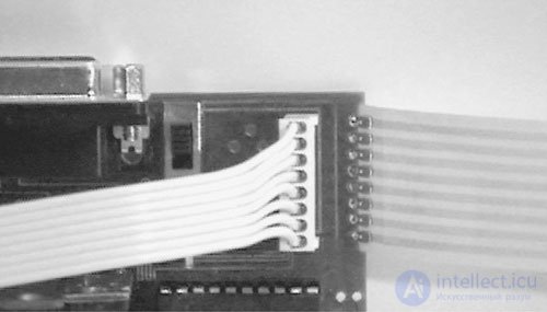
Fig.15.10. Manual control connection
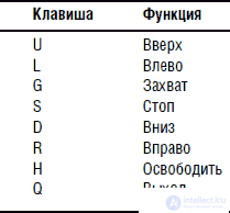
Program DOS control with keyboard
There is a DOS program that allows you to control the operation of the manipulator arm from a computer keyboard in interactive mode. The list of keys corresponding to the execution of a particular function is given in the table.
Voice-controlled hand manipulator
In voice control, a hand manipulator uses a speech recognition set (OCR), which was described in Ch. 7. In this chapter, we will build an interface that connects ORA with a hand manipulator. This interface is also offered as a set by Images SI, Inc.
The interface diagram for ORA is shown in fig. 15.11. The interface used a 16F84 microcontroller. The program for the microcontroller is as follows:
'URR interface program
Symbol PortA = 5
Symbol TRISA = 133
Symbol PortB = 6
Symbol TRISB = 134
Poke TRISA, 255
Poke TRISB, 240
Start:
Peek PortB, B0
If bit4 = 0 then trigger 'If writing to the trigger is allowed, read the scheme
mu ovd
Goto start 'Repeat
trigger:
pause 500 'Wait 0.5 s
Peek PortB, B0 'Read BCD Code
If bit5 = 1 then send 'Output code
goto start 'Repeat
send:
peek PortA, b0 'Reading port A
if bit4 = 1 then eleven 'Is the number 11?
poke PortB, b0 'Output code
goto start 'Repeat
eleven:
if bit0 = 0 then ten
poke portb, 11
goto start 'Repeat
ten:
poke portb, 10
goto start 'Repeat
end
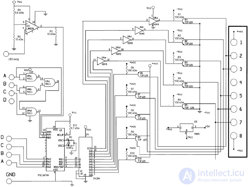
Fig.15.11. Scheme controller URR for hands-robot
Software update under 16F84 can be downloaded for free from http://www.imagesco.com
URR interface programming
Программирование интерфейса УРР аналогично процедуре программирования УРР из набора, описанного в гл. 7. Для правильной работы руки-манипулятора вы должны запрограммировать командные слова соответственно номерам, соответствующим определенному движению манипулятора. In tab. 15.1 приведены примеры командных слов, управляющих работой руки-манипулятора. Вы можете выбрать командные слова по вашему вкусу.
Table 15.1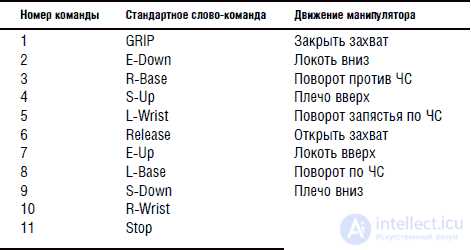
Список деталей для интерфейса PC
• (5) Транзистор NPN TIP120
• (5) Транзистор PNP TIP 125
• (1) ИС 74164 преобразователь кода
• (1) ИС 74LS373 восемь ключей
• (1) Светодиод красный
• (5) Диод 1N914
• (1) Гнездо разъема Molex на 8 контактов
• (1) Кабель Molex 8-жильный длиной 75 мм
• (1) Двухпозиционный переключатель
• (1) Разъем уголковый типа DB25
• (1) Кабель DB 25 1,8 м с двумя разъемами М – типа.
• (1) Печатная плата
• (10) Резистор 100 кОм, 0,25 Вт
• (3) Резистор 15 кОм, 0,25 Вт
• (1) ИС регулятор напряжения 7805
Все перечисленные детали входят в комплект набора.
Список деталей для интерфейса распознавания речи
• (5) Транзистор NPN TIP 120
• (5) Транзистор PNP TIP 125
• (1) ИС 74154 4/16 – декодер
• (1) ИС 4011 логический элемент ИЛИ-НЕ
• (1) ИС 4049 – 6 буферов
• (1) ИС 741 операционный усилитель
• (1) Резистор 5,6 кОм, 0,25 Вт
• (1) Резистор 15 кОм, 0,25 Вт
• (1) Головная часть разъема Molex 8 контактов
• (1) Кабель Molex 8 жил, длина 75 мм
• (10) Резистор 100 кОм, 0,25 Вт
• (1) Резистор 4,7 кОм, 0,25 Вт
• (1) ИС регулятор напряжения 7805
• (1) ИС PIC 16F84 микроконтроллер
• (1) Кварцевый резонатор 4,0 МГц
• Набор интерфейса руки-манипулятора
• Набор для изготовления руки манипулятора компании OWI
• Интерфейс распознавания речи для руки-манипулятора
• Набор устройства распознавания речи

Comments