Lecture
The “intellect” concluded in the robot takes one of two forms: software-supported intelligence (expert system) and intelligence in the form of a neural network. Perhaps the simultaneous functioning of these forms of intelligence. Such a synthesis over time will be widely used in robots to create systems of developed AI.
Expert AI programs based on the decision rule system are well known to most PC users. These are programs written in a high or low level language such as C ++, Basic or assembly language. On the other hand, neural systems use artificial, electronic neurons to control and generate the behavior of a robot. A similar architecture of building neural networks that control the behavior of robots was first proposed by William Gray Walter in the late 40s and early 50s. Later, Rodney Brooks from the Massachusetts Institute of Technology developed a behaviorally oriented structure of networks of robots called predicative (conditional) architecture. We will look at the work of behaviorally oriented robots in ch. eight.
In this chapter we will focus on programmable systems and microcontrollers. Remember that the work of neural networks can be simulated using special software systems. It is noteworthy that almost all software on neural networks operates on ordinary programmable computers, using special programs to simulate the operation of networks.
Single chip PIC microcontroller
At present, supplying the “intelligence” of a small robot or robotic system is a fairly simple task. There is a whole family of single-chip computers (better known as microcontrollers) capable of performing various jobs.
As the name implies, a single-chip computer is a one-piece computer device enclosed in an IC case. The microcontroller, made on a miniature silicon substrate, contains the features and capabilities of a conventional personal computer (PC). First of all, the microcontroller is able to store and execute programs, which is its most important feature. The controller contains a central processor (CPU), random access memory (RAM), read-only memory (ROM), I / O buses, serial and parallel ports, timers, and some other peripheral devices such as ADC and DAC.
Reasons for using a microcontroller
The ability of the microcontroller to store and execute a unique (user-defined) program makes it flexible. For example, a microcontroller can be programmed to make decisions (execute functions) based on pre-defined I / O bus conditions and sensor readings. Its ability to produce mathematical and logical operations allows modeling complex logical chains and the operation of digital electronic circuits. Programs of another kind make it possible to simulate the operation of neural networks and devices with fuzzy logic.
The microcontroller is able to control the operation of DC motors (voltage control or PWM is used), servomotors, stepper motors, etc. If you program the microcontroller's responses to the readings of sensitive sensors and the remote control command, the robot will acquire the ability of “intelligent” response. Currently, all the most "smart" electronic devices in the consumer market are equipped with microcontrollers, which, obviously, can be used in our robots.
Details of PIC microcontroller programming
Programming the PIC microcontroller occurs in three stages. However, before you start programming yourself, you need to purchase two things: the PICBASIC compiler program and the EPIC programmer (the board where the microcontroller is placed). The PIC microcontroller itself and its additional parts do not apply to these components. I recommend starting with a 16F84 type PIC microcontroller, since it is a fairly versatile device in an 18-pin package with 13 I / O buses and rewritable flash memory. Flash memory allows up to 1000 reprogramming cycles. This will be quite useful when testing and debugging programs and electrical circuits.
The PICBASIC compiler (Fig. 6.1) can be installed on a standard PC. The program works under DOS or in the MS-DOS Prompt window when Windows is installed. For brevity MS-DOS Prompt we will be denoted further simply as a DOS window. The DOS program can be run on any PC, ranging from PC XT with DOS version 3.3 or higher. The compiler supports a wide range of PIC microcontrollers. The compiler generates hexadecimal machine code that can be used with other programmers. The price of the PICBASIC compiler software is about $ 99.95.

Fig. 6.1. PICBASIC compiler
The EPIC programmer board (see Fig. 6.2) has a panel for inserting the PIC controller IC and a connection to a PC through the printer port for programming. The programmer board connects to the computer using a DB25 cable inserted into the printer port (parallel port). If your computer has a single parallel port into which the printer cable is already inserted, then this cable must be disconnected before programming the PIC. Paired with the PICBASIC compiler, the EPIC programmer board supports the programming of many types of PIC microcontrollers. The cost of the programmer board, together with the supplied floppy disk, is $ 59.00
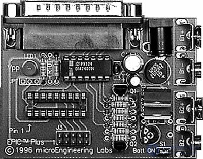
Fig. 6.2. EPIC programming board
The PIC 16F84 microcontroller is depicted in Fig. 6.3. It is a universal device equipped with flash-memory. Flash memory, as noted above, is a rewritable memory. The memory allows at least 1000 erase-write cycles, so you can reprogram and reuse the microcontroller up to 1000 times. Memory retention time without rewriting is approximately 40 years. Of the 18 pins of the IC 16F84, 13 are I / O buses. Changing the status of I / O buses can be easily implemented from the program. Other features include power management on restart, power saving mode, on timer and code protection. Other features of the PIC 16F84 architecture will be described as we go along.
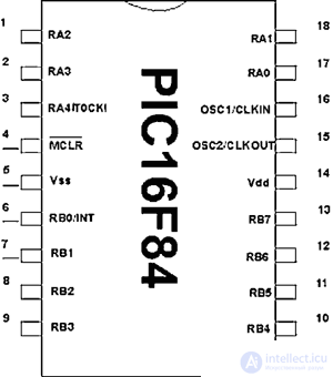
Fig. 6.3. 16F84 microcontroller
Software download
First of all, you need to download the PICBASIC compiler software and the EPIC programmer according to the instructions given in their descriptions. To boot, I created a directory on your hard drive called APPLICS. In order to call the compiler and programmer from the same directory, I used the DOS path pointer. All the necessary text files I created and saved in the same directory APPLICS. For a complete software installation, including a full list of DOS commands, along with the PIC Microcontroller Programming Guide, read my PIC Microcontroller Project Book (McGraw-Hill, New York, 2000).
Step 1: Writing a program in the BASIC language
PICBASIC programs must be written in a text editor capable of creating text files in ASCII or DOS text format. All modern editors that I used have this feature. Use the Save as command and select the MS-DOS text, DOS text or ASCII text extension. The finished text is compiled using PICBASIC. If you do not have a text editor, then use the Windows Notepad program, which is available in Windows versions 3.x, 95, 98, in order to write the source file to BASIC. (On Windows, see Applications.) In the DOS shell, you can use the EDIT editors.
When saving a file, it is necessary to provide it with an extension. bas. If you save the program as Wink, then its full name will be Wink.bas.
Step 2: Compile the program
The PICBASIC compiler is started with the pbc command line with the name of the required text file. For example, if we called the file wink.bas, the command line in the DOS command prompt would be:
pbc wink.bas
The BASIC compiler processes the source file and creates two additional files: .asm (file in assembly language) and. hex (file in hexadecimal machine codes).
The file wink.asm is a translation of the BASIC file into assembly language. The wink.hex file is a machine code file written in hexadecimal. A file is loaded for programming the PIC. hex
If the compiler detects errors when compiling the source text on BASIC, it will mark each of them in the line containing this error and interrupt the operation. In order to successfully complete the compilation, you must first correct all marked errors in the source code of the program.
Step 3: Programming the PIC IC
Connect the programmer board to the computer's printer port using a DB25 cable. Switch to DOS fashion. At the command prompt, type:
EPIC
In fig. 6.4 shows a view of the monitor screen. Use the Open File option and select the wink.hex file from the list in the dialog box. After downloading the file, the sequence of numbers will appear in the window on the left. Insert the PIC 16F84 into the panel and press the Program key. The PIC microcontroller is programmed and ready to go.
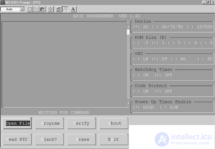
Fig. 6.4. EPIC programming window
The first program in the language of BASIC
Now we are ready to write our first program. Enter the program using a text editor exactly as shown below:
'The first program on BASIC for alternately blinking two LEDs connected to port B.
Loop: High 0 'Turn on the LED connected to RB0 port
Low 1 'Turn off the LED connected to RB1 port
Pause 500 '0.5 second delay
Low 0 'Turn off the LED connected to RB0 port
High 1 'Turn on LED connected to RB1 port
Pause 500 '0.5 second delay
goto loop 'Go to Loop label alternately blinking LEDs
End
Look at the pic. 6.5. Save this text as a text file using the Save command in the file menu. Name the file wink.bas (see Figure 6.6). If you accidentally saved the text as wink.txt, do not be discouraged. You can easily rename the file to wink.bas in the file menu of the editor using the Save as command.
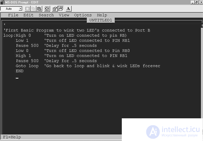
Fig. 6.5. PICBASIC text file
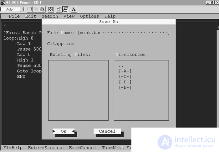
Fig. 6.6. Save text file
The PICBASIC compiler must be run under the DOS system or from the DOS prompt window in the Windows system. I started the compiler from the APPLICS directory. Make sure that the file wink.bas is also located in the PICBASIC compiler directory. The PICBASIC compiler is compatible with many types of different PIC microcontrollers. To compile a program for an existing microcontroller, you must tell the program its type. To compile a program under PIC 16F84, you need to add -p16f84 to the pbc command.
Thus, the full team will look like: pbc -p16f84 wink.bas. At the DOS prompt, type the command and press the enter key (see Figure 6.7).
C: \ APPLICS> pbc –p16f84 wink.bas
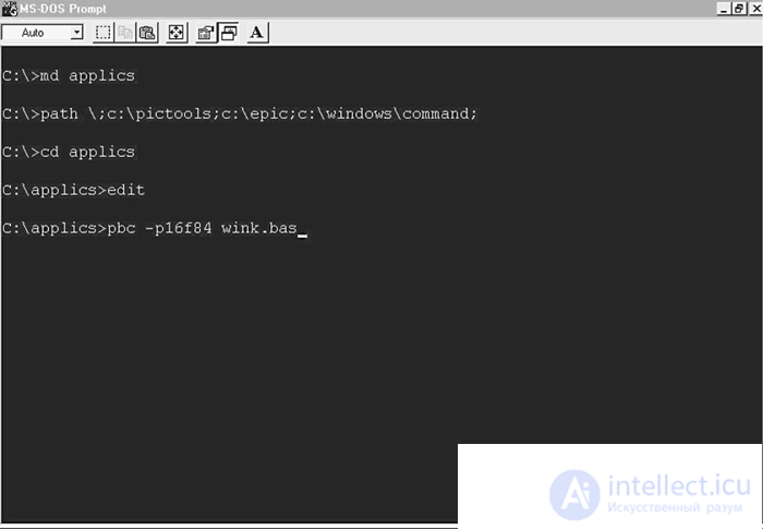
Fig. 6.7. Introduction of the compilation command
The compiler will display a header containing the name of the version and begin to compile the source text (see Figure 6.8). If the source text on BASIC does not contain errors, it will create two additional files. If the compiler finds errors, it will produce a list of errors with the number of the corresponding line. Match the error line numbers with the source lines. The compiler will terminate the program only if all errors are corrected.

Fig. 6.8. Compiler program
You can view the received files with the dir command. Type dir in the command line and press the enter key (see Figure 6.9).
C: \ APPLICS> dir
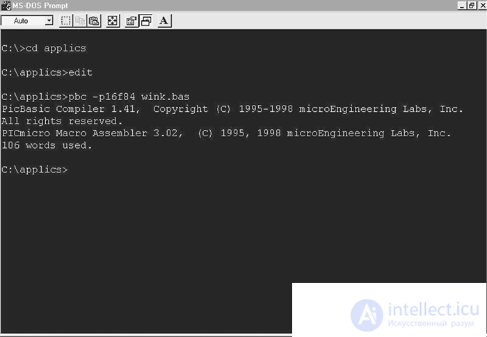
Fig. 6.9. Command directory
The dir command displays all subdirectories and files contained in this directory. In Figure 6.9 you can see the appearance of two additional files. One of them is the wink.asm file, which is an assembler language source file that automatically runs a macro assembler to convert the assembler code to hexadecimal machine code. The second file created is the wink.hex file containing hexadecimal machine code.
PIC programming
To program the PIC, you need to connect the EPIC programmer board to the computer (see. Fig. 6.10). The EPIC card connects to the printer port. If the computer contains a single printer port, then unplug the printer, if it was connected, and connect the EPIC card with a DB25 cable that is 2 meters long.
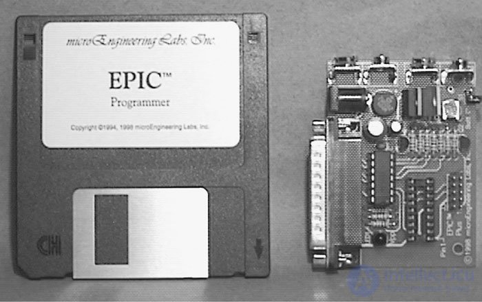
Fig. 6.10. EPIC Programmer Board
When connecting the card, pay special attention to the fact that the PIC microcontroller is not inserted into the card. If you have an external network power supply for the programmer board, insert it into the appropriate slot. If you do not have a mains supply, use two new 9 V batteries and switch the “Batt on” jumper to supply voltage. The connection of the board to the computer and the supply of voltage must be made before running the programs. Otherwise, the computer will not “see” the device connected to the printer port and will display the error message “EPIC programmer not connected”.
After energizing and connecting to the printer port on the programmer board, the LED may light up and go out. Until the completion of the communication setup program in the EPIC programmer, do not insert the PIC microcontroller into the programmer socket.
EPIC Programmer Board Software
There are two versions of EPIC software: EPIC.exe for DOS and EPICWIN.exe for Windows. Windows software is 32-bit and can be used under Windows 95, 98, and NT versions, but not suitable for 3.X.
Using the DOS version of EPICWhen using a version of Windows 95 or higher, you can open the MS-DOS prompt or restart the computer in the DOS mode. Under Windows 3.XX, you must end the session.
Suppose we are in a DOS mode and have just completed the compiling of wink.bas using the pbc compiler. Copy the file wink.hex to the EPIC directory. In the DOS prompt mode, type "EPIC" and press the enter key to launch the DOS version of the EPIC program (see Figure 6.11).
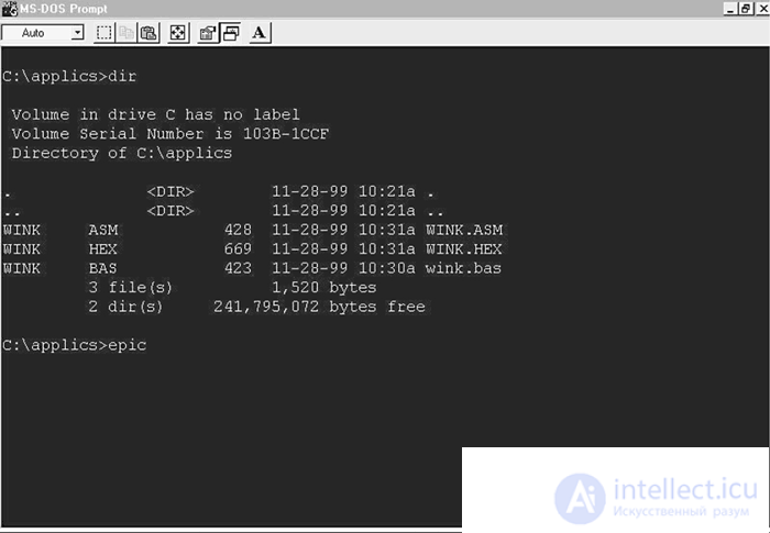
Fig. 6.11. EPIC commands
The display of the EPIC program on the monitor is shown in Fig. 6.12. Use the mouse to press the Open key or press the Alt + O key on the keyboard. Select the wink.hex file (see fig. 6.13). When the hex file loads, you will see a sequence of numbers in the window on the left (see Figure 6.14). This sequence is the machine code of the program. On the right side of the screen, the configuration parameters are displayed, which we will need to set before starting the programming of the PIC IC.
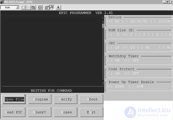
Fig. 6.12. EPIC window
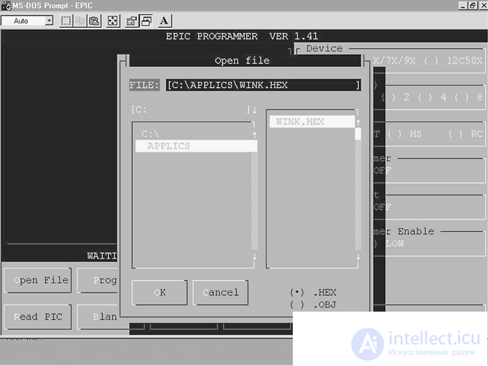
Fig. 6.13. Hex file selection
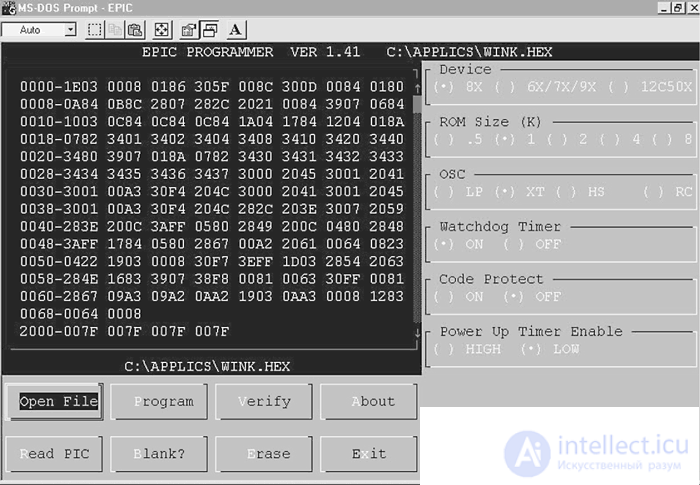
Fig. 6.14. Hex file uploaded to EPIC
Let's review the list of configuration parameters in order of priority:
• Device: Determine the type of device. Set the parameter to 8X.
• ROM size (K): Sets the ROM memory capacity. Choose 1.
• OSC: Set the oscillator type. Choose CT for a quartz resonator.
• Watchdog timer: Select On.
• Code protect: Choose Off
• Power-up time enable: Select High.
After setting the parameters, insert the 16F84 PIC microcontroller into the socket. Click on Program or press Alt + P on the keyboard to start programming. First of all, the EPIC program determines whether the memory of the microcontroller IC is “empty”. In this case, the EPIC program installs the program you specified into the microcontroller. If the memory of the microcontroller is not empty, then an option is given to interrupt the execution of the program or write a new program over the existing one. If a program already exists in the microcontroller's memory, write over it. As the PIC is programmed, the machine code working lines are highlighted. After the process is complete, the microcontroller is programmed and fully operational.
Check PIC microcontroller
The diagram shows that for the operation of the microcontroller requires a very small number of additional parts. First of all, you need a bias resistor connected to pin 4 (MCLR), a 4 MHz crystal oscillator with two 22 pF capacitors and a 5 V power supply.
At the output of the device are connected two LEDs connected in series with the limiting resistors. They will allow us to evaluate the correctness of the microcontroller. Connect the components without soldering on the breadboard in accordance with the diagram in fig. 6.15. The finished device will look like the one shown in Fig. 6.16.
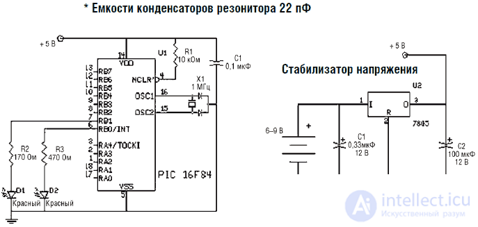
Fig. 6.15. Scheme
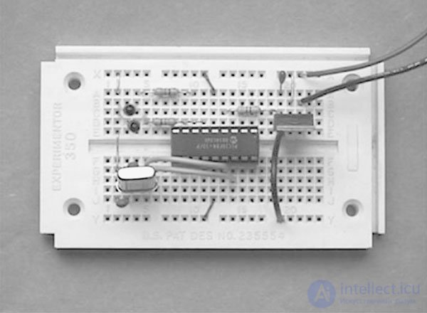
Fig. 6.16. The circuit mounted on the breadboard
Although the specification for IC 16F84 claims that the microcontroller is capable of operating in the voltage range from 2 to 6 V, I preferred to use a stabilized 5 V power supply. The voltage regulator includes a voltage regulator on the IC 7805 and two filter capacitors.
Blinking
Power up the circuit. Светодиоды, подключенные к ИС, начнут попеременно включаться и выключаться, поочередно мигая… Теперь вы знаете, что для программирования микроконтроллера и его запуска требуются совсем небольшие усилия.
По мере накопления опыта использование компилятора и программатора станет вашей «второй натурой». Процедура перестанет быть для вас «пошаговой», и все ваше внимание сосредоточится на создании наиболее эффективных программ на PICBASIC. Так должно быть и так будет.
Проверка неисправностей
В данной простой схеме ошибки практически не встречаются. Если Светодиоды не включаются, то необходимо проверить полярность их включения. Если они включены с обратной полярностью, то они не будут зажигаться.
Компилятор PICBASIC Pro
Существует старшая версия компилятора PICBASIC, которая имеет название PICBASIC Professional компилятор. Версия Pro компилятора гораздо бо-: лее дорогая и стоит порядка $249,95. Версия Pro имеет гораздо больший и развернутый набор команд, чем стандартная версия компилятора. Некоторые из таких команд, которые содержатся в Pro версии, могут управлять прерываниями, обеспечивают прямое управление ЖК-дисплеем, генерируют тоны DTMF и выдают команды Х-10.
Хотя данная версия является в целом более совершенной, она не поддерживает две из моих любимых (и очень полезных) команд: команду Peek (прочитать байт по адресу) и команду Poke (записать байт по адресу). Хотя в описании эти команды отмечены как «полезные», подчеркивается, что для версии PICBASIC Pro они не могут быть использованы. Если отбросить эмоции, такое решение представляется неудачным хотя бы потому, что оно разрушает вертикальную совместимость компиляторов PICBASIC, если в программе используются команды Peek или Poke.
Новые возможности интегрированной среды обработки (IDE)
С недавнего времени компиляторы PICBASIC и PICBASIC Pro комплектуются дополнительной дискетой, содержащей интерфейс интегрированной среды обработки информации (integrated development environment IDE), который имеет название CodeDesigner Lit (см. рис. 6.17). CodeDesigner Lite позволяет составлять и компилировать программы PICBASIC в оболочке Windows. Каждый оператор выделяется цветом, что позволяет с большей наглядностью выделять ошибки и вычитывать коды. Демонстрационная версия позволяет писать программы длиной до 150 строк и одновременно открывать до трех файлов с целью облегчения их перемещения и копирования.
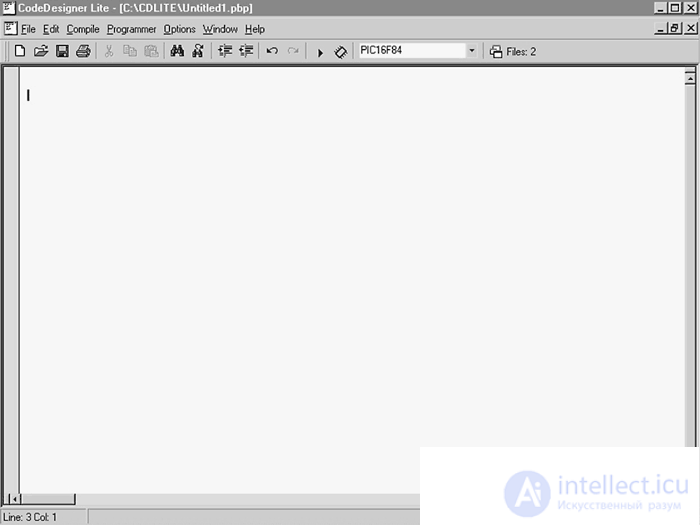
Fig. 6.17. CodeDesigner Line
Наиболее важной чертой интерфейса CodeDesigner IDE является возможность сперва ввести исходный текст программы, потом компилировать программу в машинный код и, наконец (теоретически), запрограммировать микроконтроллер в пределах одного окна Windows. Такая компоновка уменьшает время работы программы. Обычно я пишу программу в DOS моде или использую окно MS-DOS Prompt под Windows. После окончания я выхожу из режима редактора и вручную компилирую программу. Если программа содержит ошибки (что чаще всего и происходит), я опять вхожу в редактор и произвожу отладку программы. Когда программа полностью отлажена, я загружаю ее в микроконтроллер с помощью программатора и программы EPIC. После этого производится тестирование микроконтроллера и остальной схемы. Если все работает правильно, то задача решена; в противном случае я начинаю переписывать программу.
При использовании CodeDesigner легкость написания и отладки программы на PICBASIC, а также загрузки ее в микроконтроллер сильно повышают производительность работы. Мой опыт показывает, что оптимальным является создание и отладка программы под Windows, но программирование лучше осуществляется в DOS моде.
Демонстрационной версии CodeDesigner Lite для большинства случаев оказывается достаточно, но по желанию можно расширить ее до полной версии CodeDesigner. CodeDesigner имеет любительскую версию за $45,00 и стандартную версию за $75,00.
Любительская версия CodeDesigner может работать только с компилятором PICBASIC. Стандартная версия поддерживает оба компилятора: PICBASIC и PICBASIC Pro. Некоторые отличительные характеристики CodeDesigner приведены ниже:
• Автодополнение текста: CodeDesigner делает написание текста программы более простым с помощью всплывающих окон Windows, автоматически заполняемых необходимыми операторами и данными.
• Поддержка работы с несколькими файлами.
• Подсвечивание строк, содержащих ошибки: CodeDesigner во время компиляции текста PICBASIC считывает информацию об ошибках и подсвечивает соответствующие строки программы.
• Синтаксическая поддержка: Опция оперативной синтаксической поддержки отображает синтаксис операторов среди допустимых операторов PICBASIC.
• Описание оператора: Если оператор является допустимым для PICBASIC, дескриптор оператора появляется в поле строки состояния.
• Разъяснения функций операторов: Достаточно поставить курсор на оператор PICBASIC, чтобы получить разъяснения его функции.
• Список меток: Окно списка меток высвечивает текущую метку и позволяет вам выбрать нужную метку из списка для осуществления перехода.
• Выделение цветом в PICBASIC: Возможно выделять различным цветом различные слова, строки, данные, комментарии, определения и т. д. Подобное выделение позволяет более легко читать текст программы PICBASIC.
• Закладки: Для отметки нужных мест в программе CodeDesigner имеет систему закладок.
• Возможность отмены/назначения предыдущего действия: Если вы по ошибке удалили строку, то для ее восстановления необходимо нажать клавишу «отменить».
• Система окон просмотра: Наличие нескольких окон просмотра позволит вам легко редактировать текст программы.
• Печать текста программы.
• Перемещение и вставка текста.
• Возможность вставки, удаления и копирования по строкам и столбцам.
• Поиск и замена в тексте.
• Компиляция и запуск устройства программатора.
Установка программного обеспечения
В процессе установки компонент CodeDesigner создает поддиректорию в директории Program Files и устанавливается туда. Ярлык CodeDesigner помещается в меню программ Windows.
Первая программа на PICBASIC PRO
Данная программа аналогична по функции программе wink.bas для PICBASIC, но текст ее имеет отличия. Запустите программу CodeDesigner (Lte) – см. рис. 6.18 – и введите следующий текст:
' Программа мигалка
' Попеременное мигание двух светодиодов, подключенных к порту В
Loop:
High PORTB.0 'Включить светодиод, подключенный к порту RB0
Low PORTB.1 'Выключить светодиод, подключенный к порту RB1
Pause 500 'Задержка Ѕ с
Low PORTB.0 'Выключить светодиод, подключенный к порту RB0
High PORTB.1 'Turn on LED connected to RB1 port
Pause 500 'Delay s
got Loop 'Jump by Loop label for continuous flashing LEDs
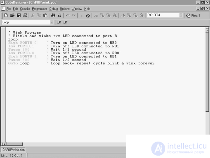
Fig. 6.18. PICBASIC Pro software written with CodeDesigner
CodeDesigner by default creates an output code for the PIC 16F84 microcontroller. This is the type of microcontroller I would recommend to start with. To change the device type, call the device menu and select the appropriate type of microcontroller in it.
Для компиляции программы необходимо выбрать команду компиляции в соответствующем меню или нажать клавишу F5. CodeDesigner автоматически загрузит компилятор PICPASIC Pro для осуществления компиляции. Перед началом компиляции необходимо выбрать соответствующие опции в меню компилятора. CodeDesigner «попросит» выбрать директорию, в которой находится программа PICBASIC Pro и директорию для сохранения исходного и компилированного файлов.
После завершения компиляции мы можем приступить к следующему этапу – загрузке программы в микроконтроллер с помощью программатора EPIC. Необходимо следовать порядку, изложенному ранее в инструкции для компилятора PICBASIC.
CodeDesigner и программатор EPIC
По желанию вы можете запрограммировать ИС также с помощью CodeDesigner. Выберите опцию «загрузить программатор» в меню программатора или нажмите F6. CodeDesigner автоматически запустит EPICWIN.exe под Windows.
Когда программа EPIC под Windows запущена, необходимо установить параметры конфигурации в меню опций:
• Device: Установите тип устройства. Поставьте опцию 16F84 (по умолчанию).
• Memory size (K): Устанавливает емкость ПЗУ. Поставьте 1.
• OSC: Установка типа осциллятора. Установите ХТ – кварцевый резонатор.
• Watchdog timer: Таймер режима ожидания. Установите On.
• Code protect: Защита кода. Установите Off.
• Power-up timer enable: таймер режима включения. Установите High.
После установки параметров конфигурации вставьте микроконтроллер PIC 16F84 в панельку платы программатора EPIC. В случае если CodeDesigner при запуске программы EPIC выдает ошибку «программатор EPIC не найден» (см. рис. 6.19), вы можете либо произвести диагностику программы, либо попробовать запустить EPIC в DOS моде. Инструкции по запуску матобеспечения EPIC под DOS приведены в разделе описания PICBASIC. Схема тестового устройства аналогична схеме для компилятора PICBASIC.
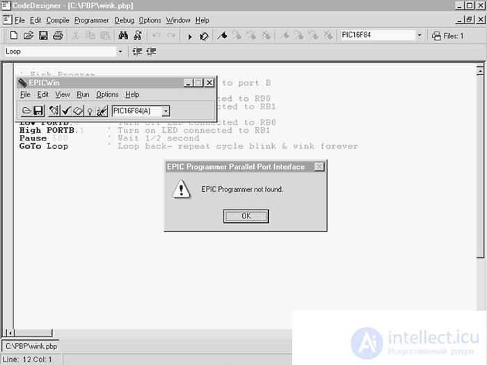
Fig. 6.19. Запуск программы EPIC из CodeDesigner
Мигание
Включите питание схемы. Светодиоды, подключенные к микроконтроллеру, будут попеременно включаться и выключаться.
Движемся дальше – приложения использования микроконтроллера
Сейчас настало время продемонстрировать вам, как используются микроконтроллеры в различных схемах. Вы уже обладаете начальным опытом программирования микроконтроллера 15F84. В этой главе приведены некоторые основные функции использования микроконтроллеров в различных устройствах. Эти функции повсеместно реализуются в микроконтроллерах, используемых в различных схемах и разработках.
Для начала посмотрим, как микроконтроллер может определить замыкание цепи. Для этой цели могут быть использованы любые из 13 шин ввод/вывод, которые работают в логике TTL. Для определения замыкания мы будем использовать эти логические уровни в соединении с выключателями (см. рис. 6.20).
Выключатели низкого уровня
In fig. 6.20 выключатель с меткой А выдает на шину ввода/вывода сигнал высокого логического уровня до момента замыкания. После замыкания шина «садится» на землю, т. е. получает сигнал низкого уровня. Когда микроконтроллер получает сигнал замыкания, он может произвести ряд операций или функций управления. В нашем случае замыкание контакта выключателя вызовет мигание светодиода. Понятно, что светодиод может быть заменен транзистором, преобразователем, электронной схемой или другим микроконтроллером или компьютером.
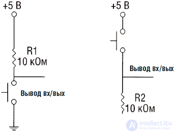
Fig. 6.20. Переключатели логических уровней
Программа на PICBASIC имеет следующий вид:
'PICBASIC компилятор
'REM проверка выключателя низкого уровня
' Инициализация переменных
input 4 'Назначить шину PB4 для определения состояния выключателя
start:
if pin4 = 0 then blink 'Если выключатель выдает низкий уровень – све
тодиод мигает
goto start 'Если нет – проверить состояние выключателя
blink: 'Процедура мигание
high 0 'Высокий уровень на шине RB0 для зажигания светодиода
pause 250 'Задержка ј с
low 0 'Низкий уровень на шине RB0 для гашения светодиода
pause 250 'Задержка ј с
goto start 'Проверка состояния выключателя
Программу на PICBASIC Pro можно составить следующим образом:
'REM BASIC Pro компилятор
'Rem проверка выключателя низкого уровня
input portb.4 'Назначить шину PB4 для определения состояния выключателя
start:
if port.b = 0 then blink 'Если выключатель выдает низкий уровень – све
тодиод мигает
goto start 'Если нет – проверить состояние выключателя
blink: 'Процедура мигание
high 0 'Высокий уровень на шине RB0 для зажигания светодиода
pause 250 'Задержка ј с
low 0 'Низкий уровень на шине RB0 для гашения светодиода
pause 250 'Задержка ј с
goto start 'Проверка состояния выключателя
Схема устройства для выключателя низкого уровня приведена на рис. 6.21. Выключатель соединен с шиной ввода/вывода, помеченной RB4. Светодиод соединен с шиной RB0 через ограничительный резистор 470 Ом.
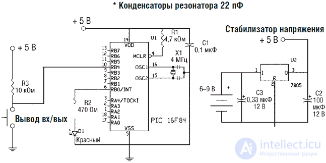
Fig. 6.21. Схема ключа низкого уровня
Выключатели высокого уровня
Programs and circuit solutions for this case are complementary to the previous example. Look again at pic. 6.20 - option B. If the switch labeled B is in the "off" position, the output bus has a low logic level. When the switch is closed, a high logic level signal is sent to the bus.
The PICBASIC program is as follows:
'PICBASIC compiler
'REM high level switch check
'Initializing Variables
input 4 'Assign bus PB4 to determine the state of the switch
start:
if pin4 = 1 then blink 'If the switch gives a high level -
LED blinks
goto start 'If not, check the status of the switch
blink: 'flashing procedure
high 0 'High level on bus RB0 for ignition of the LED
pause 250 'Delay s
low 0 'Low level on the bus RB0 for quenching the LED
pause 250 'Delay s
goto start 'Check the status of the switch
The PICBASIC Pro program can be composed as follows:
'REM BASIC Pro compiler
'Rem check high level switch
input portb.4 'Assign bus PB4 to determine the state of the switch
start:
if port.b = 0 then blink 'If the switch gives a high level -
LED flashes
goto start 'If not, check the status of the switch
blink: 'flashing procedure
high 0 'High level on bus RB0 for ignition of the LED
pause 250 'Delay s
low 0 'Low level on the bus RB0 for quenching the LED
pause 250 'Delay s
goto start 'Check the status of the switch
Diagram of the device for the high level switch is shown in Fig. 6.22. The switch is connected to the I / O bus labeled RB4. The LED is connected to the RB0 bus through a 470 ohm limiting resistor.
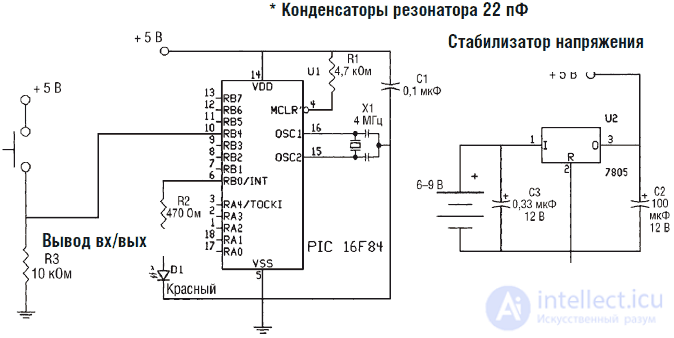
Fig. 6.22. High-level key schema
Reading comparator data
The microcontroller can also read logic level data from other microcontrollers, circuits, and ICs. As an example, consider the scheme in Fig. 6.23. In this circuit, the microcontroller reads the comparator output data. The output of the comparator LM339 is built according to the NPN transistor circuit, so to create a high level signal, you must use a bias resistor. The microcontroller reads the comparator output data in the same way as the low level switch algorithm.
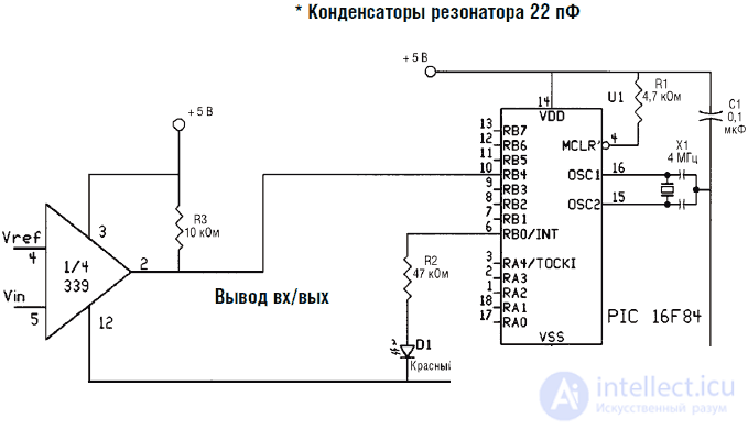
Fig. 6.23. Comparator reading scheme
Reading resistive sensor data
The microcontroller can directly read the resistive sensor data in the range from 5 to 50 kΩ. A resistive sensor of any type can be connected to the microcontroller: a photoresistor (element based on cadmium sulfide CdS), a thermistor with a positive or negative TC, a sensor for the presence of toxic gas, a sensor for bending or humidity. The microcontroller measures the resistance of the discharge time of the capacitor in the RC chain (see. Fig. 6.24).
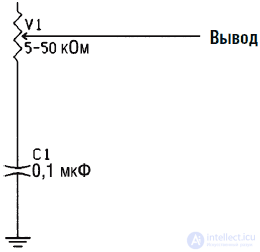
Fig. 6.24. ROT team diagram
The command to read resistive sensor data is:
Pot pin, scale, var
Pot is the command name, and pin is the bus number to which the sensor is connected. The variable scale is used to set the RC time. With a large RC time, the scale value should be low, and for a small RC time, the scale chain should be set to a maximum value of 225. If the scale value is set correctly, the value of the var variable will be close to zero with a minimum resistance and reach 225 - with maximum
The value of the scale variable can be determined experimentally. In order to find an appropriate scale value, it is necessary to determine the maximum operating resistance of the sensor and read the var readings when the scale parameter is set to 225. Under this condition, the value of the var variable will be a good approximation of the scale value.
The main scheme is shown in Fig. 6.25. To simulate a resistive sensor, a 50 kΩ resistor is included in the circuit. When the resistance of the variable resistor changes, depending on the value of the variable B0, one of the two LEDs will light up. If the resistance value exceeds 125 - LED 1 will light up, otherwise LED 2 will be on.
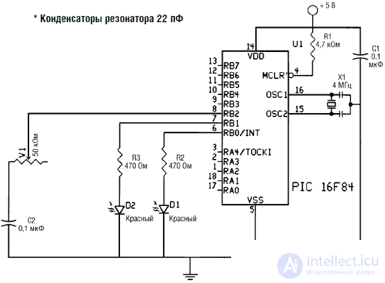
Fig. 6.25. ROT team diagram
The PICBASIC program is as follows:
'PICBASIC compiler ** reading resistive sensor data **
'Test? Program for photoresistance
'Installation
start:
pot 2,255, b0 'Read the sensor on the bus RB2
if b0> 125 then l1 'If the value is greater than 100, turn on the LED 1
if b0 <= 125 then l2 'If the value is less than 100, turn on LED 2
l1: 'LED 1 turn-on procedure
high 0 'Turn on LED 1
low 1 'Turn off LED 2
goto start 'Repeat
l2: LED 2 turn-on procedure
high 1 'Turn on LED 2
low 0 'Turn off LED 1
goto start 'Repeat
The program for the PICBASIC Pro compiler can be composed as follows:
'PICBASIC Pro Compiler ** reading resistive sensor data **
'Test? Program for photoresistance
'Installation
output portb.0 'Installing the RB0 bus as output
output portb.1 'Installing the RB1 bus as output
b0 var byte
start:
portb.2,255, b0 'Read the sensor reading on the RB2 bus
if b0> 125 then l1 'If the value is greater than 100, turn on the LED 1
if b0 <= 125 then l2 'If the value is less than 100, turn on LED 2
l1: 'LED 1 turn-on procedure
high 0 'Turn on LED 1
low 1 'Turn off LED 2
goto start 'Repeat
l2: LED 2 turn-on procedure
high 1 'Turn on LED 2
low 0 'Turn off LED 1
goto start 'Repeat
You can make the demonstration more interesting by replacing the variable resistance with a CdS-based photoresistor. With proper selection of a resistor, the dark resistance of which is from 50 to 100 kΩ and the light saturation resistance is about 10 kΩ or less, when the resistor is closed or in the dark, LED 1 will light up. In bright light, LED 2 will be lit.
It is possible to serially output the numerical value of the variable pot to the LCD display connected to the microcontroller via the serial port, or to the PC via the RS232 serial port. To organize a serial port, the following command is needed:
Serout Pin, Mode, Var
Now we will not consider the connection through the serial port; it is important that you get an idea about it.
Servomotors
Servomotors are DC motors with a gearbox, equipped with a feedback system that allows you to position the position of the rotor of the servo motor with high accuracy. The shaft of most servomotors for amateur design can be positioned in a rotation range of at least 90 ° (± 45 °). The servomotor has three outputs. The two terminals are connected to a power source, usually from 4.5 to 6 V and to the earth wire. The third wire is fed a feedback signal, positioning the rotor of the motor. The positioning signal is a chain of pulses of variable duration. Typically, the pulse duration varies in the range from 1 to 2 ms. Its duration pulses control the position of the servo shaft.
The pulsout command generates a pulse of a given duration on a given bus in 10 μs increments. Thus, the command pulseout 1, 150 will emit pulses with a length of 1.5 ms on the bus 1. A pulse with a length of 1.5 ms will turn the servo shaft into the middle position.
Servo Swing Program
The demonstration program will swing the servo shaft from the left to the right and back again in the same way as a parabolic radar antenna. Diagram of the device is shown in Fig. 6.26.
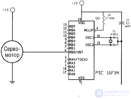
Fig. 6.26. Servo power on circuit
Below is a program for the PICBASIC compiler:
'Servo rocking program
'PICBASIC compiler
'The program performs the swing from the left position to the right and back
b0 = 100 'Initialization of the left position
sweep: 'straight pass procedure
pulsout 0, b0 'Sending a pulse to a servomotor
pause 18 'Waiting 18 ms (50 to 60 Hz)
b0 = b0 + 1 'Increase pulse length
if b0> 200 then sweepback 'End of straight stroke?
goto sweep 'No, continuation of the straight passage
sweepback: 'Backward pass procedure
b0 = b0 - 1 'Reducing the pulse length
pulsout 0, b0 'Sending a pulse to a servomotor
pause 18 'Waiting 18 ms (50 to 60 Hz)
if b0 <100 then sweep 'End of reverse?
goto sweepback 'No
Program for the PICBASIC Pro compiler:
'Servo rocking program
'PICBASIC Pro Compiler
'The program performs the swing from the left position to the right and back
b0 var byte
b0 = 100 'Initialization of the left position
sweep: 'straight pass procedure
pulsout portb.0, b0 'Sending a pulse to a servomotor
pause 18 'Waiting 18 ms (50 to 60 Hz)
b0 = b0 + 1 'Increase pulse length
if b0> 200 then sweepback 'End of straight stroke?
goto sweep 'No, continuation of the straight passage
sweepback: 'Backward pass procedure
b0 = b0 - 1 'Reducing the pulse length
pulsout portb.0, b0 'Sending a pulse to a servomotor
pause 18 'Waiting 18 ms (50 to 60 Hz)
if b0 <100 then sweep 'End of reverse?
goto sweepback 'No
Fuzzy logic and neural sensors
When interpreting sensor data, you can take advantage of some interesting features. With the help of a microcontroller, we can simulate the operation of neural networks and / or fuzzy logic devices.
Fuzzy logic
The first works on fuzzy logic were published in 1965 by a professor at the University of California at Berkeley Lotfi Zade. From the very beginning, the principles of fuzzy logic were both heavily advertised and criticized.
In essence, fuzzy logic tries to imitate a person’s approach to the definition of groups and classes of phenomena. The definition of "fuzziness" can be explained with some examples. For example, on the basis of what criterion can a warm sunny day be defined, not as “warm”, but how hot and by whom? The basis on which someone defines a warm day as hot can be a personal sensation of warmth, which in turn depends on his or her environment (see Figure 6.27).

Fig. 6.27. Temperature change from warm to hot: smoothly or abruptly
There is no universal thermometer that “claims” that 26.9 ° C is warm and 27 ° C is already hot. If we look at this example more broadly, then the people living in Alaska will have a different temperature range for “warm days” compared to New Yorkers, and both of these values will differ from the corresponding values for Florida residents. At the same time, it is not necessary to forget about the seasons. A warm winter day differs in temperature from a summer one. It all comes down to the fact that the basis of the classification (for example, the concept of a “warm day”) can be the range of temperatures determined by the opinion of a group of people. Further classification can be carried out by comparing the opinions of different groups of people.
For any temperature we can find a group in the temperature range of which it falls. In some cases, the temperature may fall into two intersecting groups. A clear group membership can be determined by the deviation of the value from the group average.
The idea of group or interval classification can be extended to many other things, such as orientation, speed, or growth. Let's use the concept of growth for another example. If we build a growth chart of 1000 people, its shape will resemble the first curve in fig. 6.28. We can use this chart to form groups of people of small, medium and high growth. If we apply a rigid decisive rule to consider everyone below 170 cm to be low-growth people and all above 180 people to be tall, then the graph will take the form 2 in fig. 6.28. This rule considers the height of 178 cm "average", although in reality a person of this height is closer to the group of "tall" (from 180 cm and above).
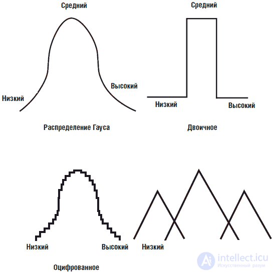
Fig. 6.28. Grouping people according to height according to different rules.
Instead of the rules of rigid "fast" logic, usually used in computers, a person, as a rule, uses softer, imprecise logic or fuzzy logic. To introduce fuzzy logic into the computer, we define the groups themselves and the degree of belonging to the group. Thus, a person with a height of 178 cm will almost not belong to a group of people of medium height (weak presence) and confidently belong to a group of high growth (strong presence).
Fuzzy logic is an alternative to digitized graphics, shown at number 3 in Fig. 6.28. The graph, digitized with high resolution, allows you to measure growth with the same accuracy. What is the reason for using fuzzy logic instead of using a digitized model? The fact is that methods of fuzzy logic require simpler forms of software and learning functions.
To simulate fuzzy logic in groups, it is necessary to create numerical intervals of values in the PIC microcontroller. This we will do in the next project.
Fuzzy logic device - light source tracking system
Now we will begin to manufacture the device - a tracking system for the direction of the light source using the principle of fuzzy logic. The system tracks the direction to the light source using fuzzy logic.
For the construction of the tracking system, we will need two CdS photo cells, which are photosensitive resistive sensors (see. Fig. 6.29). The resistance of such an element varies in proportion to the intensity of the light flux falling on the sensitive surface of the photocell. In dark conditions, the element has the greatest resistance.
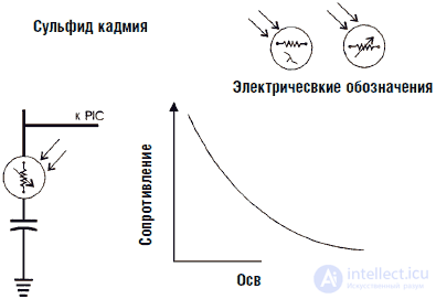
Fig. 6.29. Electrical characteristics of CdS photocell
There are many different types of CdS photo cells available. The choice of a suitable element is based on the dark resistance of the element and the resistance of the light saturation. The term "light saturation resistance" means the minimum resistance of an element, which ceases to decrease with an increase in the level of illumination, that is, it becomes saturated. I use CdS photocells with a dark resistance of about 100 kΩ and a light saturation resistance of about 500 ohms. Under medium lighting conditions, the resistance varies between 2.5 and 10 kΩ.
The project will require two CdS photo cells. It is necessary to check each element separately, since within the elements of one type there is a variation of parameters, which will require a change in the scaling factor. For the pot command, I used a capacity of 0.022 microfarads and a multiplier parameter of the scale of 225.
The schematic diagram of the device is shown in Fig. 6.30. CdS photocells are connected to the port B bus (physical pin numbers 8 and 9).
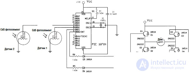
Fig. 6.30. Scheme of the tracking system for the light source
Photocells are mounted on a small plate of plastic or wood (see. Fig. 6.31). Small holes are drilled in the plate for the photocell leads. From the reverse side to the terminals, conductors connected to the PIC terminals of the microcontroller are soldered.
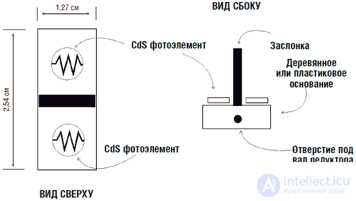
Fig. 6.31. Sensor block design
To fix the shaft of the engine gearbox, a hole is drilled from 2.4 mm to 3 mm. The gearbox shaft is passed through a hole in the sensor unit and secured with glue (see fig. 6.32).
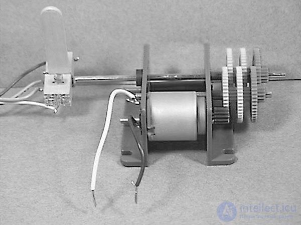
Fig. 6.32. Photograph of the sensor unit mounted on the engine gearbox
The operation of the tracking system is shown in Fig. 6.33. With the same illumination of both sensors, their respective resistances are about the same. Within ± 10 PIC units, the program considers them the same and does not include a turning device. In other words, a group of "sameness" is formed with a span of 20 units. Such a group is a group of fuzzy logic.
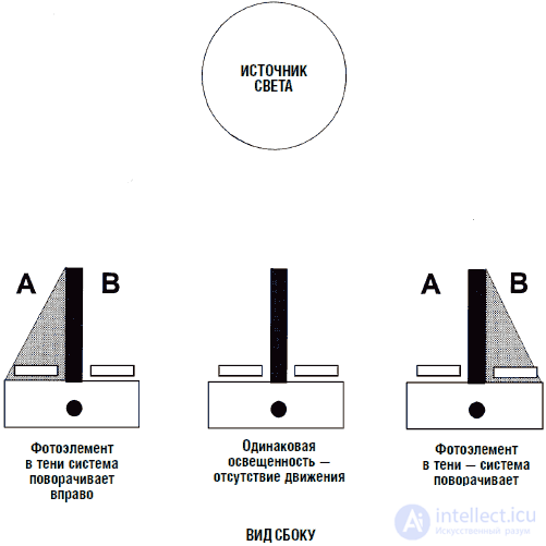
Fig. 6.33. The work unit sensors depending on the direction of the light source
When one of the sensors enters the shadow zone, i.e. the difference in sensor readings exceeds a range of 20 units, the PIC microcontroller starts the engine turning the sensor unit towards the light source (i.e. equal to the sensor illumination).
DC motor controlTo rotate the sensor unit in the direction of the light source, the device uses a DC motor with a gearbox (see. Fig. 6.34). The reduction ratio of the gear 4000: 1. The shaft of the gearbox has a speed of approximately 1 revolution per minute. When repeating a design, it is recommended to use a motor with a gearbox having similar characteristics to rotate the sensor unit.
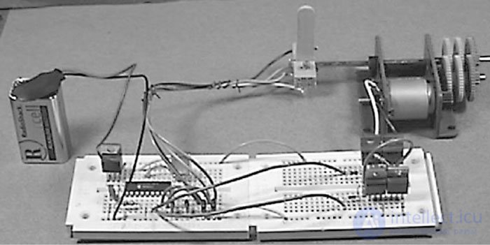
Fig. 6.34. Photo of the assembly of the tracking device assembly
The sensor block is attached (glued) to the motor gearbox shaft. The motor through the gearbox can turn the unit clockwise or counterclockwise, depending on the direction of the current flowing through the motor.
To ensure that the direction of rotation of the motor is reversed, a device is necessary that allows current to flow in both directions. For this purpose we use a bridge circuit. In the bridge circuit uses four transistors (see. Fig. 6.35). Consider each transistor as a simple key, as shown at the top of the figure. The circuit is called pavement, since the transistors (keys) included it in the form of a bridge.
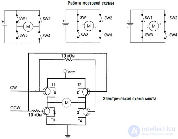
Fig. 6.35. The operation of the bridge circuit and its device
With the closure of the keys SW1 and SW4, the motor rotates in one direction. When the switches SW2 and SW3 are closed, the motor rotates in the opposite direction. If the keys are open, the engine stops.
Управление мостом осуществляется с помощью PIC микропроцессора. Мостовая схемы включает в себя четыре NPN транзистора типа 120 Darlington, четыре диода типа 1N514 и два резистора 10 кОм 0,25 Вт. Вывод 0 подключен к транзисторам Q1 и Q4. Вывод 1 подключен к транзисторам Q2 и Q3. Сигналами на выводах 0 и 1 открываются соответствующие транзисторы и двигатель вращается по или против часовой стрелки соответственно данным блока датчиков. Обратите внимание на правильность подключения резисторов 10 кОм, в противном случае схема не будет работать.
Транзисторы TIP 120 Darlington изображены на схеме как обычные NPN транзисторы. Во многих схемах моста в «верхней» части используются транзисторы PNP проводимости. Сопротивление PNP транзисторов немного выше. Таким образом, если мы используем только NPN транзисторы, то КПД устройства несколько увеличится.
ДиодыДля предотвращения выбросов напряжения, которые могут привести к сбросу или зависанию PIC микропроцессора, используются защитные диоды, включенные между эмиттером и коллектором каждого транзистора (от Q1 до Q4). Эти диоды гасят всплески напряжения, возникающие при включении и выключении обмоток двигателя.
Программа на PICBASIC имеет следующий вид:
'Программа нечеткой логики для системы слежения
start:
low 0 'Низкий уровень шины 0
low 1 'Низкий уровень шины 1
pot 2,255,b0 'Чтения показаний фотоэлемента 1
pot 3,255,b1 'Чтение показаний фотоэлемента 2
if b0 = b1 then start 'Если показания равны, то ничего не делать
if b0 > b1 then greater 'Если больше, то насколько
if b0 < b1 then lesser 'Если меньше, то насколько
greater: 'Процедура больше
b2 = b0 – b1 'Определение разницы показаний
if b2 > 10 then cw 'Внутри границ? Если нет, перейти на cw
goto start: 'Если внутри границ, измерять снова
lesser: 'Процедура меньше
b2 = b1 – b0 'Определение разницы показаний
if b2 > 10 then ccw 'Внутри границ? Если нет, перейти на ccw
goto start: 'Если внутри границ, измерять снова
cw: 'Поворот блока по часовой стрелке
high 0 'Включить мост
pause 100 'Вращение 0,1 с
goto start 'Новая проверка
сcw: 'Поворот блока против часовой стрелки
high 1 'Включить мост
pause 100 'Вращение 0,1 с
goto start: 'Новая проверка
Работа устройстваПри работе система слежения поворачивается вслед за перемещением источника света. Если оба CdS фотоэлемента освещены примерно одинаково, то поворота не происходит. Для проверки работы устройства закройте пальцем один из CdS датчиков. Это должно вызвать включение двигателя и поворот вала редуктора.
Если вал вращается в направлении, противоположном заданному, то поменяйте либо входные проводники датчиков, либо выходные проводники управления мостовой схемой, но не обе операции одновременно.
Выход, не использующий нечеткую логикуУстройство системы слежения с нечеткой логикой имеет двоичный выход. Двигатель может находиться в трех состояниях: выключено и вращение по и против часовой стрелки. Во многих случаях требуется плавное (градуальное) изменение выходного сигнала. Допустим, вы проектируете устройство управления двигателем лифта. Необходимым условием в данном случае будет постепенное, а не резкое ускорение или остановка лифта (двигатель не должен просто включаться и выключаться).
Возможно ли подобное изменение схемы нашего устройства? Yes of course. Вместо простого включения двигателя, мы можем запитывать его сигналом ШИМ, который управляет скоростью его вращения.
В идеале скорость вращения двигателя должна быть пропорциональна разнице показаний (сопротивлений) двух CdS датчиков. Большая разница будет приводить к большей скорости вращения. По мере вращения датчика и приближения его к положению равновесия скорость вращения двигателя будет динамически изменяться.
Такая программа управления выходом может быть иллюстрирована графиками, разбиениями на группы и принадлежностью к группе в терминах нечеткой логики. В данном случае использование подобной программы для системы слежения является избыточным.
В целях эксперимента вы можете использовать команды pulsout и pwm для управления скоростью вращения двигателя.
Нейронные датчики (логика)При помощи простой программы мы можем превратить датчики нечеткой логики (CdS фотоэлементы) в нейронные датчики. Нейронные сети представляют собой обширную область, мы же ограничимся одним небольшим примером. Для тех, кто решил углубленно изучить строение нейронных сетей, я рекомендую собственную книгу Understanding Neural Networks (Prompt, Indianapolis, 1998, ISBN 0-7906-1115-5).
Для создания нейронного датчика мы возьмем численные значения каждого датчика, умножим их на соответствующие весовые коэффициенты и суммируем результирующие величины. Полученный результат затем будет сравниваться со значением трехуровневого порогового значения (см. рис. 6.36).
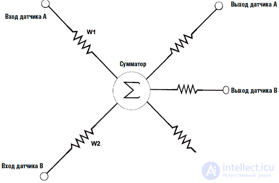
Fig. 6.36. Схема трехуровневого нейрона
Наша небольшая программа и датчики могут выполнять все функции, присущие нейронной сети. Более того, введение многоуровневых пороговых значений является нашей оригинальной разработкой. Существуют ли многопороговые системы в природе (биологические системы)? Да, несомненно. Зуд или чесотка представляет собой очень незначительную по уровню боль, а жжение может ощущаться как жары, так и от действия холода.
Многоуровневые пороговые значенияКак правило, отдельные нейроны нейронной сети имеют единственный порог (положительный или отрицательный). Если значение превышает пороговое, то нейрон активируется. В нашем случае выходной сигнал сравнивается с несколькими пороговыми значениями и попадает, таким образом, в соответствующую группу.
Вместо того чтобы рассматривать группы выхода как диапазоны численных значений, воспользуемся геометрической интерпретацией. Рассмотрим группы как группы круга, квадрата и треугольника соответственно. При накоплении значения «на нейроне» его выходом будет служить геометрическая форма, а не численное значение. Выходные нейроны (светодиоды) могут быть собраны в матрицы соответствующей формы. При попадании сигнала в определенную группу загорается соответствующая матрица.
В нашем случае каждый из уровней выхода нейрона мы будем относить к трем группам характерного «поведения»: спячке, охоте и кормлению, которые отражают основные типы поведения «выживания» для робота «охотника за светом». Выбор типа «поведения» основывается на текущем уровне освещенности. При низком уровне освещенности робот-охотник прекращает охоту и поиски пищи (света). Включается режим сна или спячки. При средних уровнях освещенности робот «охотится» и выискивает места с наибольшим уровнем света. При высоких уровнях освещенности «охотник» останавливается и «питается», подзаряжая солнечные батареи.
В этой главе мы не будем изготовлять полную модель робота-охотника, лишь ограничимся использованием светодиодов как индикаторов типа соответствующего поведения (см. рис. 6.37). Можно обозначить светодиоды как «спячка», «охота» и «питание». Каждый из светодиодов зажигается в зависимости от интенсивности светового потока, принимаемого CdS фотоэлементами.
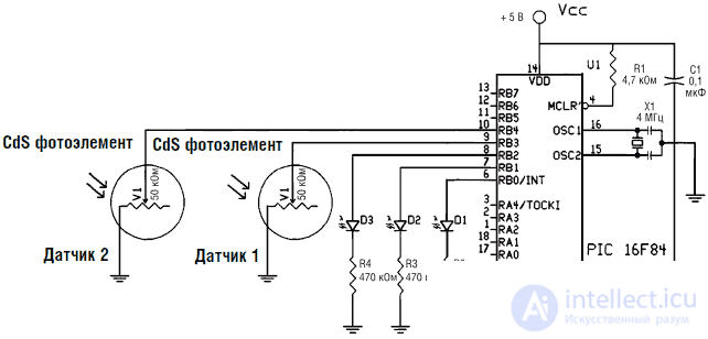
Fig. 6.37. Схема основной нейронной цепочки
Программа на PICBASIC имеет следующий вид:
'Демонстрация работы нейрона
'Установка параметров
low 0 'Светодиод 1 «спячка» выключен
low 1 'Светодиод 2 «охота» выключен
low 2 'Светодиод 3 «питание» выключен
start:
pot 3,255,b0 'Считывание показаний первого датчика
pot 4,255,b1 'Считывание показаний второго датчика
w2 = b0 * 3 'Умножение на весовой коэффициент
w3 = b1 * 2 'Умножение на весовой коэффициент
w4 = w2 + w3 'Сложение результатов
'Установка пороговых значений
if w4 < 40 then feed 'Много света. Nutrition
if w4 <= 300 then hunt 'Света среднее количество. Hunting
If w4 > 300 then snooze 'Света мало. Спячка
'Действия
feed: 'Кормление
low 0
low 1
high 2
goto start:
hunt: 'Охота
low 0
high 1
low 2
goto start:
snooze: 'Спячка * не использовать ключ sleep *
goto start
Список необходимых частей для программирования микроконтроллера
• компилятор PSIBASIC
• компилятор PSIBASIC Pro (включая CodeDesignerLit)
• программатор EPIC
• компилятор PICBASIC и программатор EPIC
• CodeDesigner любительская версия
• CodeDesigner стандартная версия
• 16F84-4 1 шт.
• кварцевый резонатор 4,0 МГц
• конденсатор 22 пФ 2 шт.
• конденсатор 0,1 мкФ
• конденсатор 100 мФ 12 В
• резистор 4,7 кОм 0,25 Вт
• резистор 470 Ом 0,25 Вт
• стабилизатор напряжения 7805
• светодиод миниатюрный
• плата макетная
• Набор для экспериментов PIC–LED-02 (Включает: PIC16F84 (1), кварц 4,0 МГц (1), конденсатор 22 пФ (2), резистор 10 кОм 0,25 Вт (1), регулятор напряжения 7805 (1), макетная плата (2,1" х 3,6", 270 монтажных отверстий)(1), резистор 470 Ом (8), миниатюрный светодиод (8), кнопка-выключатель (1), руководство по двоичному коду, логике и портам ввода/вывода А и В)
• Сервомотор с усилием 1,3 кгс
Список деталей для системы слежения за направлением источника света и демонстрационного нейрона
• (2) CdS фотоэлемент
• (1) датчик изгиба (номинальное сопротивление 10 кОм)
• (2) конденсатор 0,22 мкФ
• (1) конденсатор 0,01 мкФ
• (4) транзистор NPN TIP 120 Darlington
• (2) резистор 10 кОм
• (б) диод 1N514
• (2) резистор 1 кОм
• двигатель с редуктором 4000:1

Comments