Lecture
Platforms are the base of mobile robots. There are two ways: buy such a platform or make it yourself. If you have skills in metalworking or simply a desire to learn, then making a platform from the very beginning has obvious advantages. Such a platform is designed and manufactured specifically for the goals and objectives set for the robot. It does not matter the type of engines used, gearboxes, mechanical connections, power supplies, etc.
Buying a finished platform frees from its independent production. But, on the other hand, suitable off-the-shelf engines, gearboxes, power sources and speeds were originally intended for other purposes. One feature is most important: most existing car models move too fast. If there are no plumbing skills, then this may be the way out. Usually purchased radio-controlled model of an electric car. The radio control circuit is removed, and the electrical connections (wires) to the stroke and turn engines are retained.
Here are a few points to consider when buying an electric car for later rework. First, do not purchase a car that is too small or too close to the ground. In a small model, it is difficult to place touch sensors and microcontrollers on the chassis. If the bottom of the car is too close to the ground, it will constantly get stuck. Choose an instance with a high wheelbase.
In fig. 10.1 shows a model of a car that you should not choose to convert to a mobile robot. It is too small to bear the extra load, and notice how close it is to the ground. Such a car will be easily stuck. In fig. 10.2 shows the best option. The size of the platform is larger (you can place more parts) and it has a large wheelbase.
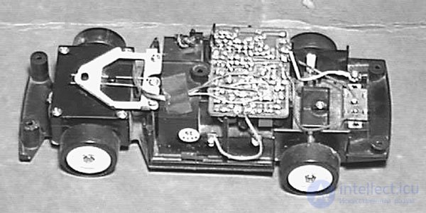
Fig. 10.1. A small model of a radio-controlled car is not suitable for rework
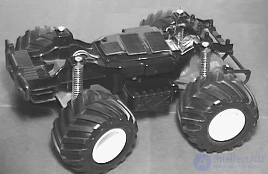
Fig. 10.2. A large model of a radio-controlled car is suitable for rework
Stepper motors
In as a platform propulsion engine is best to use stepper motors. Consider some of the advantages of such engines. Since the stepping motor rotates at a strictly defined angle at each step, the microcontroller can easily calculate the distance traveled, knowing the number of control pulses fed to the stepping motor and the diameter of the drive wheel. In the case of application on a mobile platform of two stepper motors, one on each side, used for direct movement and rotation, turns out to be possible to turn at an exact predetermined angle. Due to the special importance of stepper motors for robotics, before designing and manufacturing any devices, we will elaborate on the principles of their operation.
The design and operation of a stepper motor
Stepper motors are designed using permanent magnets and electromagnets. Permanent magnets are located on a rotating shaft, which is called a rotor. Electromagnets or winding coils are located in a fixed part of the engine and are called a stator. Fig. 10.3 illustrates the full cycle of a stepper motor. The windings of the stator, the fixed part of the engine, surround the rotor from all sides.
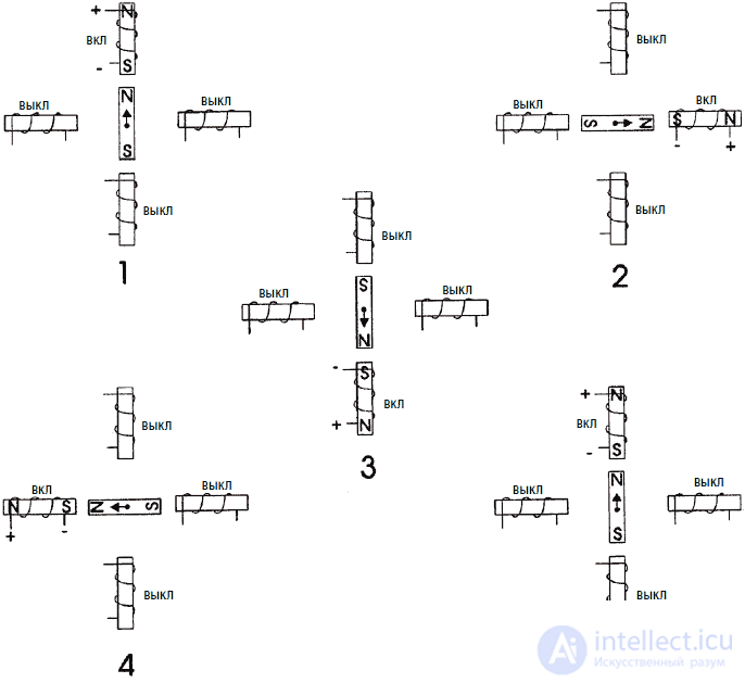
Figure 10.3. Full step
In Fig. 10.3, position 1, the rotor is in the initial position and is directed to the upper electromagnet, which is turned on. To turn the rotor clockwise, the upper electromagnet is turned off and the winding of the right electromagnet is turned on. This causes the rotor to rotate 90 ° clockwise towards the right electromagnet, as shown in position 2. Continuing in the same way, the rotor is rotated to full rotation until it reaches its initial position, as shown at position 5.
Resolution
The angle of rotation for each incoming pulse is called the resolution of the stepping motor. In the illustrative example in fig. 10.3 The rotor turned 90 ° per impulse - not very suitable for practical use. Real stepper motors have a much higher resolution (lower pitch angular magnitude), for example, having a rotation angle of 1 ° per pulse (or pitch). To complete a complete revolution on such an engine, 360 pulses must be applied. When a stepping motor is used to move or linearly position on a surface, each step of the motor is converted to a strictly measured linear motion.
Assume that one motor revolution corresponds to a 25 mm linear displacement. Then the increment of linear displacement for a motor with a resolution of 3.75 ° per step will be approximately 0.25 mm per step. For an engine with a resolution of 1 ° per step, the corresponding increment will be 0.007 mm per step. Accordingly, the increment of the linear displacement will be inversely proportional to the number of degrees by one step.
Half step
For some types of stepper motors, it is possible to double their resolution using a process called half step. This process is illustrated in Fig. 10.4. In position I, the rotor starts rotation from the upper electromagnet, as it was before. In position II, the right electromagnet is turned on, while the power of the coil of the upper electromagnet is maintained. Since the current flows through the coils of both electromagnets, the rotor is attracted to both of them and occupies an intermediate position between the two positions (half step). In position III, the winding of the upper electromagnet de-energizes and the rotor “completes” a full step. Only one half step is shown here. Obviously, the rotor can rotate in half steps during a full turn.
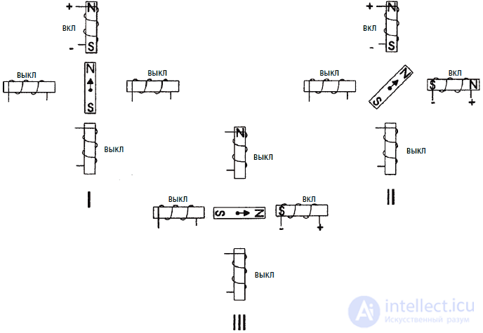
Fig. 10.4. Half step
Other types of stepper motors
There are four stepping motors. Such stepping motors are called bipolar and have two windings, each of which has two leads. Although the design of such an engine is simpler than those we use, it requires a more complex scheme for controlling its rotation. Such a scheme should change the direction of the current in the windings after the step.
Real types of SD
The stepper motor in the considered example had a rotation angle of 90 ° per step. The stators and rotors of real stepper motors are sequences of mini-poles. Mini-poles reduce the angle of rotation in steps to improve the resolution of the stepper motor. Scheme of the stepper motor in Fig. 10.5 seems to be more complicated, however, its principle of operation is identical to that in fig. 10.3 and 10.4.
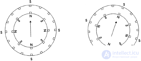
Fig. 10.5. Multi-pole control
The rotor of the engine in Fig. 10.5 rotates clockwise. In the initial position, the north pole of the permanent magnet of the rotor will be attracted to the south pole of the stator electromagnet. Note that there are several such pairs of magnets attracted by opposite poles. In the second position, the chain of electromagnets is turned off, and the next clockwise chain is turned on. This leads to the rotation of the rotor clockwise at a strictly defined angle. This continues in the same way for the next steps. After eight steps, the cycle ends and the repetition begins. The turn in half step is similar to that described above.
In fig. 10.6 shows a diagram of a unipolar stepper motor. The engine has six leads coming out of the hull. As can be seen from fig. 10.6, the windings are connected in pairs in series and have conclusions from the midpoint. If you have just taken such a stepping motor in your hands and know nothing about it, then the simplest method is to measure the electrical resistance between the terminals. Having made a table of correspondence between the colors of the wires of the leads and the electrical resistances between them, you will quickly figure out which leads correspond to which windings. (In some cases, the stepper motor has only five conclusions. In this case, the middle points of the windings are interconnected).
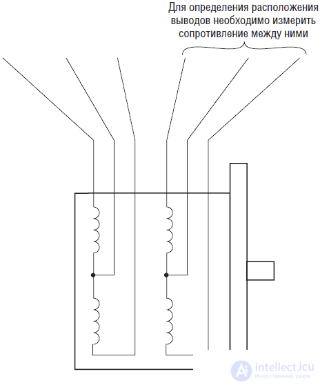
Fig. 10.6. Schematic diagram of a six-pole stepper motor
The engine that we will use has a resistance of 100 Ohms between the central terminal and the end of the winding, and accordingly 220 Ohms between the ends of the windings. It is clear that the resistance between the windings that are not connected between them will be equal to infinity (no connection). Equipped with this information, we can easily determine the pinout of the windings of any motor with six leads. The stepper motor, which we will use, has a rotation angle of 1.8 ° per step.
IC UCN-5804
In fig. 10.7 shows the pinout of the UCN-5804 IC. The IC is designed to control and power a four-phase unipolar stepper motor, which we will use in our design. IP UCN-5804 has the following parameters:
• Maximum continuous output current 1.25 A
• Reference Voltage 35 V
• Full and half step control
• Management of output state and direction of rotation
• Built-in protective diodes
• Automatic reset at power on
• Internal thermal overload protection
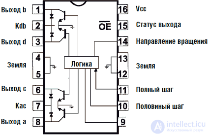
Fig. 10.7. IC UCN-5804 stepper motor controller
The IC provides, in continuous mode, a maximum output current of 1.35 A per phase with a reference voltage of 35 V. This is more than sufficient when driving a 12 volt stepper motor. The required output current for such a motor is (12V / 110O m = 0.11 A), that is, approximately 1/10 ampere.
The sequence of output pulses, determined by the internal logic of the UCN-5804, is triggered by rectangular pulses arriving at pin 11. Each rectangular pulse fed to this pin, with its negative front, starts moving the SM by one step.
The order of the windings is determined by the table. After the table ends, the sequence is repeated from the beginning of the table. To reverse the direction of rotation of the SM, the sequence of switching on the windings is determined by the table from bottom to top.
Pin 15 controls the exit status. When high potential is applied to this pin, all outputs of the IC are disabled. If this function is not required for your design, then you need to connect this pin to the ground (low level).
Table 10.1. The order of the full pulses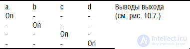
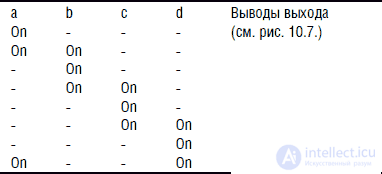
Pin 14 defines the direction of rotation. When this pin has a low level potential or is connected to an earthen tire, the direction of rotation is defined by table 10.1 or 10.2, which is read from top to bottom. When there is a high potential (15V) on this pin, the direction of rotation is reversed and is determined by tables read from the bottom up.
Uses UCN-5804
In fig. 10.8 shows a scheme for controlling the SM using the UCN-5804 IC. Clock pulses are generated using an IC 555 timer. The clock frequency can be increased or decreased using a variable resistor V1. Changing the frequency of clock pulses directly controls the speed of rotation of the SM. In this chapter, we will also show how a stepper cell can be controlled using a PIC microcontroller directly or using additional circuits.
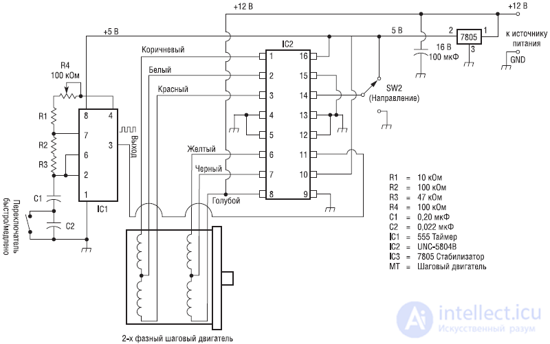
Fig. 10.8. Basic schematic diagram of stepper motor rotation control
In this scheme, additional functions are controlled using three switches. The pins of the ICs to which these switches are connected can also be controlled using the I / O bus of the same type of microcontroller. A switch connected to pin 15 controls the state of the output. When a high potential is applied, the UCN-5804 IC is turned off and the SM is stopped.
A switch connected to pin 14 controls the direction of rotation of the SM (clockwise or counterclockwise). A switch connected to pin 10 of the UCN-5804 IC switches the stepper motor to full or half step mode. When high potential is applied to pin 10, the SD is in half step mode. This mode doubles the resolution of the SM. For example, the engine we use has a resolution of 1.8 ° per step. When the half-step mode is enabled, the resolution will increase to 0.9 ° per step, and, accordingly, the rotational speed will be halved. When applying to the output 10 low level SM switches to full step mode.
Attaching a drive wheel to the shaft SM
Attaching the drive wheel to the shaft of the SM can be a problem. In fig. 10.9 shows one of the options for its simple solution. Locate a large-diameter plastic gear with a locking screw. The axial hole gear must match the diameter of the shaft SM. Attach the gear to the drive wheel in the center. Drill three through holes on the gear circle through 120 °. Fasten the drive wheel and gear with screws, nuts and washers. Then put the gear on the shaft of the SM and fix it with the fixing screw.
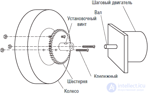
Fig. 10.9. Connecting the drive wheel to the motor shaft
The use of a microcontroller to control the SD
To study the principles of operation of the SM, we will manufacture the SD control circuit using the PIC 16F84 microcontroller.
Initial control scheme
In fig. 10.10 the first test version of the SD control circuit is shown. To buffer the output signals from the PIC 16F84, hexadecimal buffers of type 4050 are used. The signal from the output of each buffer is fed to an NPN transistor. NPN transistors Darlington TIP 120 are actually used as such transistors, but in the diagram they are designated as normal NPN transistors. The TIP 120 transistors are used in the circuit as electronic switches that ensure timely switching of the SM windings.
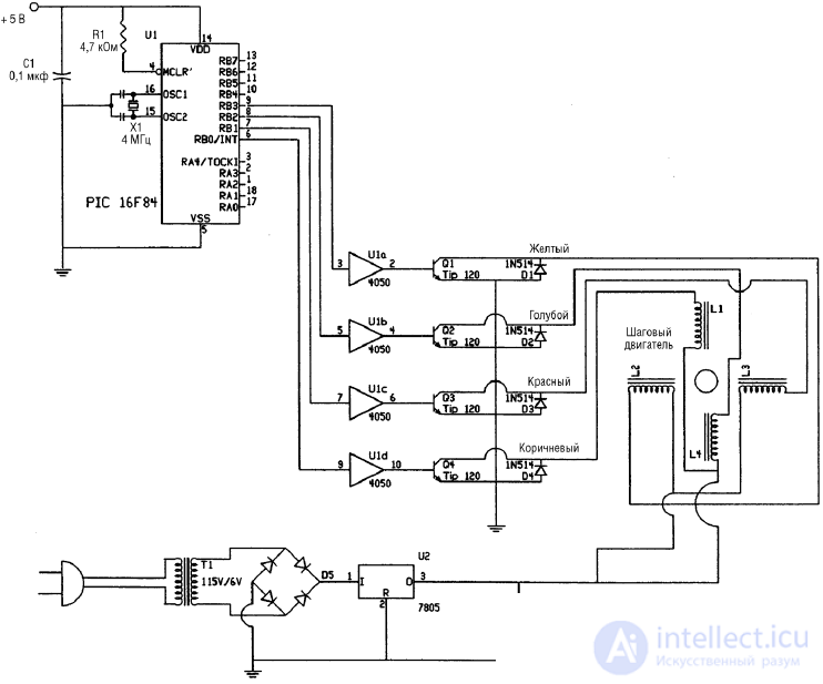
Fig. 10.10. Microcontroller circuit of a stepper motor
Diodes connected in parallel to the transistors provide damping of the current pulses arising in the inductors of the SM windings. Diodes provide safe backflow blocking. If we exclude the diodes from the circuit, then the probability of breakdown of transistors by reverse current will increase many times.
Stepper motors
In Figure 10.11. shows the equivalent electrical circuit of the engine we use. The engine has six conductors extending from its hull.
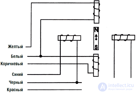
Fig. 10.11. Diagram of unipolar stepper motor leads
Suppose that we have just taken the engine in hand and know nothing about its internal structure. As I said earlier, the easiest way to find out the internal wiring of the windings is to measure the electrical resistance between the terminals. By making a table of resistances measured between the leads, you can easily determine which lead is connected to which of the windings.
In fig. 10.12 shows what resistance the engine we use has. Between the central terminal and the ends of the windings, the resistance is 13 ohms, respectively, between the ends of the windings, the resistance is 26 ohms. The resistance between the pairs of connected windings is, respectively, infinity (no connection). For example, if we measure the resistance between a brown and blue conductor, the device will show infinity. Armed with this data, we will be able to correctly include the windings of the SD in the circuit.
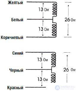
Fig. 10.12. Resistance between unipolar stepper motor leads
The program for the test control circuit
After the test control circuit has been manufactured, it is necessary to program the PIC microcontroller using the following program in the BASIC language. The program is very simple and short to show how easy it is to ensure the rotation of the SD. Table 10.3 shows how the corresponding transistor is turned on at each step. Use table 10.3 to track the logic of the BASIC program. When you reach the end of the table, the sequence repeats, starting from the beginning.
Table 10.3. Transistor Switching Logic for Full Pitch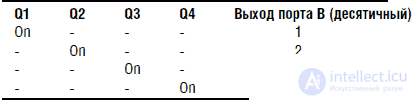
'Stepper Motor Controller
Symbol TRISB = 134 'Initialize TRISB as 134
Symbol PortB = 6 'Initialize PortB as 6
Symbol ti = b6 'Initialize ti as a delay
ti = 25 '25 ms delay
poke TRISB, 0 'Set PORTB tires to exit
start: 'Sequence forward
poke portb, 1 'Step 1
pause ti 'delay
poke portb, 2 'Step 2
pause ti 'delay
poke portb, 4 'Step 3
pause ti 'delay
poke portb, 8 'Step 4
pause ti 'delay
goto start 'Repeat
With a full step, 200 pulses (360 ° / 1.8 ° per step) are required to complete a full turn of the SM. Counting the number of pulses allows the PIC microcontroller to control and position the SD motor rotor.
The second program at PICBASIC
The second program at PICBASIC is much more flexible. Пользователь может изменять параметры программы (время задержки) во время ее работы с помощью одного из четырех выключателей, соединенных с портом А. При нажатии кнопки 1 время задержки между импульсами увеличивается, и соответственно ротор ШД вращается медленнее. Кнопка 2 обладает противоположным действием. При нажатии кнопки 3 двигатель останавливается и находится в режиме ожидания, пока эта кнопка нажата. Кнопка 4 управляет направлением вращения ШД (по часовой стрелке или против часовой стрелки). Нажатие кнопки 4 изменяет направление вращения на противоположное. Реверсирование направления вращения сохраняется на все время нажатия кнопки.
'Контроллер вращения ШД
Symbol TRISB = 134 'Инициализация TRISB как 134
Symbol TRISA = 133 'Инициализация TRISA как 133
Symbol PortB = 6 'Инициализация portb как 6
Symbol PortA = 5 'Инициализация porta как 5
symbol ti = b6 'Начальное время задержки
ti = 100 'Установка времени задержки 100 мс
Poke TRISB,0 'Установка PORTB как выхода
start: 'Вращение ШД вперед
poke portb, 1 'Шаг 1
pause ti 'Задержка
poke portb,2 'Шаг 2
pause ti 'Задержка
poke portb,4 'Шаг 3
pause ti 'Задержка
poke portb,8 'Шаг 4
pause ti 'Задержка
goto check 'Переход на проверку состояния кнопок
start2: 'Вращение ШД назад
poke portb,8 'Шаг 1
pause ti 'Задержка
poke portb,4 'Шаг 2
pause ti 'Задержка
poke portb,2 'Шаг 3
pause ti 'Задержка
poke portb,1 'Шаг 4
pause ti 'Задержка
goto check 'Переход на проверку состояния кнопок
Check: 'Состояние кнопок
Peek PortA, B0 'Загрузка состояния
if bit0 = 0 then loop1 'Если кнопка 1 нажата, увеличить ti
if bit1 = 0 then loop2 'Если кнопка 2 нажата, уменьшить ti
if bit2 = 0 then loop3 'Остановка ШД
if bit3 = 0 then start 'Вращение вперед
goto start2 'Реверсивное вращение
loop1: 'Increase delay time
poke portb, 0 'Turn off transistors
ti = ti + 5 'delay increase of 5 ms
pause 50 'pause 50 ms
if ti> 250 then hold1 'delay limit 250 ms
peek porta, b0 'Check the status of buttons
if bit0 = 0 then loop1 'Continue to increase the delay?
goto check 'If not, go to basic status check
loop2: 'Reduce delay
poke portb, 0 'Turn off transistors
ti = ti - 5 'Delay reduction by 5 ms
pause 50 'pause 50 ms
if ti <20 then hold2 'delay limit 20 ms
peek porta, b0 'Check the status of buttons
if bit1 = 0 then loop2 'Continue to reduce the delay?
goto check 'If not, go to basic status check
hold1: 'upper delay limit
ti = 245 'Delay up to 250 ms
goto loop1 'Go back
hold2: 'lower delay limit
ti = 25 '25 ms delay
goto loop2 'Go back
hold3: 'ShD stop
poke portb, 0 'Turn off transistors
peek porta, b0 'Check the status of buttons
if bit2 = 0 then hold3 'Keep motor off?
goto check 'If not, go to basic status check
Схема устройства изображена на рис. 10.13. На фотографии (рис. 10.14) трудно различить конструкцию кнопок выключателей. Они представляют собой четыре оголенных проводящих полоски позади микроконтроллера.
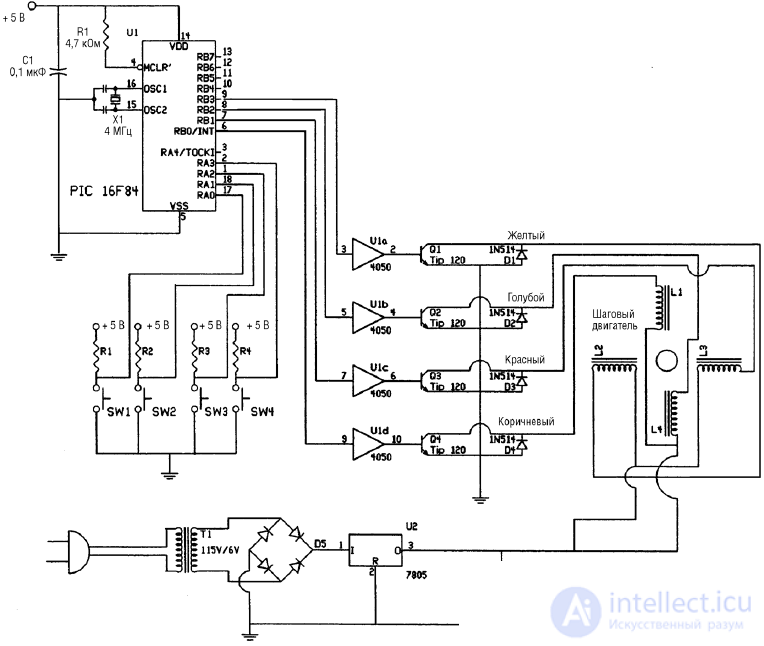
Fig. 10.13. Схема шагового микроконтроллера с дополнительными выключателями
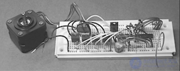
Fig. 10.14. Схема микроконтроллера шагового двигателя
Верхние половины оголенных полосок соединены с источником питания 5 В через резисторы сопротивлением 10 кОм. Проводник от каждой полоски соединен с соответствующим выводом порта А ИС. Второй контакт представляет собой оголенный одножильный проводник, соединенный с землей, на который замыкаются при нажатии на соответствующие полоски.
Половинный шагИспользование режима половинного шага эффективно удваивает разрешение ШД. В этом случае для завершения полного оборота требуется 400 импульсов. Таблица 10.4 представляет логику переключений, необходимую для работы программы. Когда вы дойдете до конца таблицы, то вы циклически вернетесь к ее началу.
Таблица 10.4. Логика переключений транзисторов для половинного шага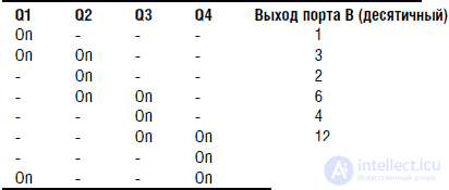
Переменная ti в каждой из программ на PICBASIC определяет время задержки, целью которой является снижение скорости следования выходных импульсов на шине В. Без этой задержки скорость следования выходных импульсов может оказаться слишком большой для обеспечения нормальной работы ШД, что приведет к сбоям в его функционировании.
Вы можете захотеть изменить значение переменной ti в зависимости от тактовой частоты работы микропроцессора, определяемой кварцевым резонатором. Проведя эксперименты, вы подберете наилучший диапазон изменения переменной ti для конкретного PIC.
Возможные неисправности
Если двигатель не вращается, проверьте полярность диодов. Убедитесь, что вы подключили их правильно, соблюдая полярность, изображенную на схеме.
Если шаговый двигатель вращается медленно или совершает колебания туда и обратно, то это может быть вызвано рядом причин.
Если вы используете питание от батарей, то батареи могут оказаться слишком слабыми для питания двигателя. Примечание: батареи истощаются достаточно быстро, поскольку ШД потребляет относительно большой ток.
В случае замены транзисторов TIP 120 NPN на транзисторы другого типа переключающий ток может оказаться слишком большим для их нормальной работы. Решение: используйте транзисторы TIP 120.
Перепутаны концы обмоток ШД, включенные в схему. Проверьте обмотки с помощью омметра и при необходимости переключите их.
Частота импульсов слишком велика. Если частота импульсов превышает время реакции двигателя, то это приведет к нарушению его правильной работы. Частота импульсов управляется переменной ti в программе. При увеличении значения этой переменой частота следования импульсов, управляющих ШД, уменьшится. Решением будет являться уменьшение частоты импульсации.
Использование PIC-микроконтроллера и ИС UCN-5804 для управления ШД
Мы использовали схему управления работой ШД непосредственно с помощью ИС PIC. Также для управления работой ШД мы использовали специализированную ИС. При совместном использовании специализированной ИС и PIC-микроконтроллера мы можем объединить преимущества, характерные для каждой из схем. ИС UCN-5804 в этом случае выполняет всю «черновую» работу по управлению работой ШД. При некотором усложнении конечной электрической схемы программа управления PIC может быть сильно упрощена, что является хорошим решением.
Принципиальная схема устройства управления ШД с использованием специализированной ИС показана на рис. 10.15, а фотография устройства приведена на рис. 10.16. Питание ИС UCN-5804 осуществляется от источника постоянного тока напряжением 5 В. При напряжении питания 5 В управляющие работой ШД напряжения могут достигать 35 В.
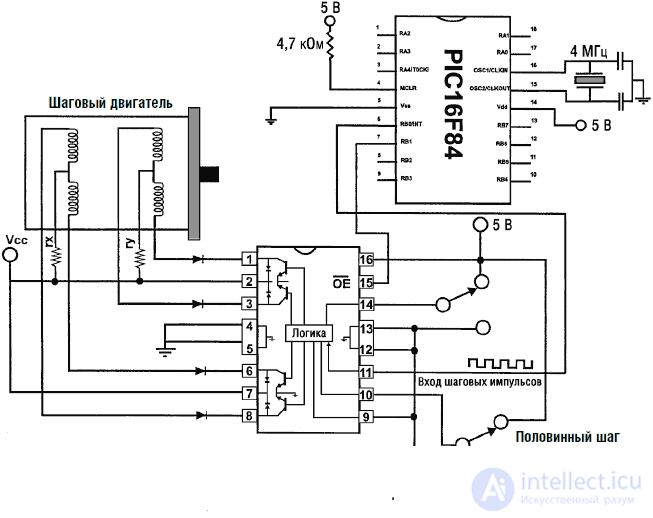
Fig. 10.15. Схема микроконтроллера шагового двигателя
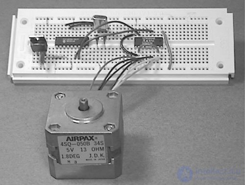
Fig. 10.16. Принципиальная схема микроконтроллера и ИС управления шаговым двигателем
Обратите внимание, что на схеме присутствуют два резистора, обозначенные «rx» и «ry» без указания их номинала. Наличие или отсутствие этих резисторов определяется типом применяемого ШД. Целью введения этих резисторов является ограничение выходного тока, протекающего через ШД, значением 1,25 А (в случае необходимости).
Рассмотрим наш ШД с напряжением питания 5 В. Его обмотки имеют сопротивление 13 Ом. Ток, протекающий через обмотки, составляет 5В/130 м=0,385А, или 385 мА, что значительно ниже максимально разрешенного значения тока 1,25 А для ИС UCN-5804. Поэтому для данного случая резисторы rx и ry не требуются и могут быть исключены из схемы.
Перед тем как мы двинемся дальше, рассмотрим еще один случай. ШД с напряжением питания 12 В имеет сопротивление обмоток 6 Ом. Ток, протекающий через обмотки ШД, составит 12 В/6 Ом=2 А. Такое значение тока превышает максимально допустимое для ИС UCN-5804. Для использование данного ШД резисторы rx и ry необходимы. Для обеспечения одинакового крутящего момента для каждой фазы сопротивления rx и ry должны быть равны. Величины резисторов должны ограничивать ток до величины 1,25 А или ниже. В данном случае сопротивление резисторов должно быть не менее 4 Ом (при мощности от 5 до 10 Вт). При включении резисторов значение тока составит 12 В/10 Ом = 1,20 А.
Уровни входов ИС UCN-5804 совместимы с выходами КМОП– и ТТЛ-логики. Это означает, что для нормальной работы схемы мы можем непосредственно соединить входы ИС с шинами выхода PIC-микроконтроллера. Входные тактовые импульсы (вывод 11) для ИС UCN-5804 генерируются PIC-микроконтроллером. Вывод управления выходом разрешает вращение ШД при подаче сигнала низкого уровня и останавливает ШД при сигнале высокого уровня.
Выводы 10 и 14 ИС UCN-5804 управляются переключателями, подающими сигналы высокого или низкого уровня. Вывод 10 управляет режимами полного или половинного шага, а вывод 14 управляет направлением вращения. При желании этими функциями можно управлять с помощью PIC. Для управления на соответствующие выводы подаются сигналы высокого или низкого уровня аналогично управлению работой выхода ИС.
Программа на PICBASIC для обеспечения работы схемы имеет следующий вид:
'Управление шаговым двигателем через ИС UCN?5804
Symbol TRISB = 134 'Инициализировать TRISB как 134
Symbol PortB = 6 'Инициализировать PortB как 6
Poke TRISB,0 'Установить шины PORTB на выход
low1 'Установить выход на низкий уровень
start:
pulsout 0, 10000 'Подача 10 мс импульсов на UCN?5804
goto start 'Повторение
В этом случае я снова написал простейшую «базовую» программу, чтобы показать, насколько просто осуществляется управление вращением ШД. Конечно, вы можете дополнить программу управлением частотой импульсов, направлением вращения и т. д.
Список деталей для контроллера ШД
• (1) микроконтроллер 16F84
• (2) конденсатор 22 пФ
• (1) кварцевый резонатор 4 МГц
• (1) резистор 4,7 кОм, 0,25 Вт
• (1) IC timer 555
• (1) ИС контроллер ШД UCN-5804B
• (1) Stepper motor (unipolar with 6 leads)
• (1) Step-down transformer
• (6) 1N914 diode
• (4) TIP 120 NPN transistor
• (1) IC voltage regulator (7805, 7812)
• (1) diode bridge 50 V, 1 A
• (1) 150 μF capacitor
• (1) IP buffer 4050
• Miscellaneous: breadboard

Comments
To leave a comment
Robotics
Terms: Robotics