Lecture
Capacitors are radio elements that can accumulate electrical discharge. However, in radio engineering, the main useful property of capacitors is that they are capable of passing alternating current without simultaneously passing a constant current. In addition, they may be part of radio filters. Depending on their task, the requirements for capacitors also change.
As is known from the general course of physics, the simplest capacitor is a parallel metal plate, separated by a dielectric. Metal plates of a capacitor are usually called its plates. The internal device of the flat capacitor is shown in Figure 1.

Figure 1. The internal device of a flat capacitor
The capacitance of a capacitor depends on the area of metal plates deposited on the dielectric, and the distance between them (the thickness of the dielectric). This dependence is described by the following formula:

where S is the area of the capacitor plates (m
2
  );
     d is the distance between the plates (m);
     ε is the dielectric constant of the dielectric;
     ε
0
- dielectric constant of vacuum ε
0
= 8.85 · 10
−12
  (F / m);
     C - Capacity of the capacitor (F).
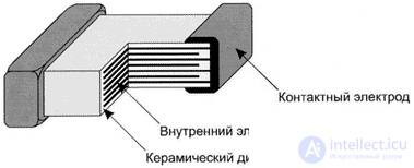
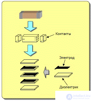
The most common currently are ceramic surface mounted capacitors. Structurally, they are a parallel connection of flat capacitors deposited on a ceramic substrate. Parallel connection allows you to increase the capacitance of the capacitor, without increasing the area occupied by the capacitor on the printed circuit board. A simplified internal arrangement of surface mounted capacitors (smd capacitors) is shown in Figure 2.

Figure 2. The internal structure of a ceramic smd capacitor

Figure 3. The process of creating a ceramic smd capacitor
The main parameter of a capacitor is its capacitance, measured as a function of its size in picofarads (1 pF = 10 −12 F), nanofarads (1 pF = 10 −9 F), and microfarads (1 pF = 10 −6 F)
No less important parameter (especially in the conditions of microminiaturization) are the dimensions of the capacitor. Now mainly used surface mount resistors. Their sizes are usually standardized and coincide with the sizes of smd resistors. However, there are exceptions. As an example, we can mention the capacitors of the firm American technical ceramics (ATC) [1]
Capacities of capacitors, depending on the circuit where they are used, require different ratings. In the manufacture of a capacitor it is necessary to obtain the required capacity. Capacities of small values (units and tens of picofarads) are obtained quite easily. In this case, it is possible to use high-quality high-frequency ceramics as a dielectric separating the capacitor plates. The result is a capacitor with high quality parameters. Changing the capacitor capacitance is possible by changing the area of the capacitor plates and reducing the distance between the plates (decreasing the thickness of the dielectric). Reducing the thickness of the dielectric at the same time leads to a decrease in the limiting voltage of the capacitor.
With an increase in the capacitance of a capacitor at a given size (and in smd capacitors, they are rigidly defined), the technological limit for reducing the thickness of the dielectric and increasing the area of the capacitor plates begins. A further increase in the capacitance (to values of the order of several thousand picofarads) is possible only by increasing the dielectric constant of the dielectric. As an analogy, it can be mentioned that an increase in the inductance of a coil can be accomplished using a ferromagnet. Dielectrics with similar electrical properties are called ferroelectrics. Some types of ceramics with a high dielectric constant of the dielectric are shown in Table 1.
Table 1. Electromechanical parameters of some types of ceramics.
| Material grade | Functional group | The dielectric constant | Curie point, ° С | Electromechanical coupling coefficient | Piezoelectric effect (d) 10 -11 , C / N, not less | |
|---|---|---|---|---|---|---|
| d 31 | d 33 | |||||
| TB-1 | one | 1500 ± 300 | 110 | 0.20 | 4.5 | ten |
| TBC – 3 | 2 | 1200 ± 200 | 95 | 0.2 | 4.3 | 8.3 |
| Tbcs | 3 | 450 ± 50 | 150 | 0.17 | 2 | five |
| PZT 19 | one | 1725 ± 325 | 290 | 0.4 | 10.0 | 20.0 |
| PTSNV-1 | one | 2250 ± 560 | 240 | 0.45 | 16.5 | 40.0 |
| PZT-23 | 2 | 1075 ± 225 | 275 | 0.43 | 10.0 | 20.0 |
| CTS-24 | 2 | 1075 ± 225 | 270 | 0.45 | 10.0 | 20.0 |
| TsBS-3 | 2 | 2300 ± 500 | 180 | 0.45 | 12.5 | 32.0 |
| CTSS-1 | 2 | 1150 ± 150 | 260 | 0.43 | 7.5 | 18.0 |
| PZT-22 | 3 | 800 ± 200 | 300 | 0.20 | 2.0 | 5.0 |
| PZT-35 | 3 | 1000 ± 200 | 300 | 0.38 | 7.0 | Not normal |
| PZT-21 | four | 550 ± 150 | 400 | 0.2 | 2.7 | 6.7 |
| NBS 1 | 2 | 1600 ± 300 | 245 | 0.28 | 6.7 | 16.7 |
| NBS-3 | 3 | 1800 ± 400 | 250 | 0.20 | 4.5 | 10.0 |
It can be seen from the table of types of ceramics that by using such ceramics without increasing the size, it is possible to increase the capacity of surface-mounted capacitors (smd capacitors) up to two thousand times. The cost of increasing the specific capacitance of the capacitors is the non-linearity of the capacity obtained. This is due to the fact that the amplitude characteristic of ferroelectrics, including barium titanate, is nonlinear. In addition, it has a hysteresis. These phenomena can lead to a significant deterioration in the parameters of electronic equipment, such as intermodulation distortion of the transmitters of cellular devices and base stations and the deterioration of the multi-signal selectivity of radio stations. In addition, capacitors made on these types of ceramics are capable of converting sonic noise and vibration into electrical signals due to the piezoelectric effect.
The next type of high-capacity capacitors are electrolytic surface-mounted capacitors. Basically, electrolytic surface-mounted capacitors are realized as tantalum capacitors, and a little less often surface-mounted polymer capacitors.
Comments
To leave a comment
Design and engineering of electronic equipment
Terms: Design and engineering of electronic equipment