Lecture
Walking robots are a class of robots that mimic the movement of animals or insects. As a rule, robots use mechanical legs to move. Movement using the legs has millions of years of history. In contrast, the history of movement using the wheel began from 10 to 7 thousand years ago. Wheeled movement is quite effective, but requires relatively flat roads. Just look at aerial photographs of the city or its suburbs to notice a network of intertwining roads.
The purpose of creating walking robots
Walking robots can move over rough terrain, inaccessible to conventional wheeled vehicles. With a similar goal, they usually create walking robots.
Imitation of life
Perfect walking robots mimic the movements of insects, crustaceans, and sometimes humans. The designs of two-legged robots are rare because they require complex engineering solutions. I plan to consider the draft bipedal robot in my next book with the provisional name Pic-Robotics. In this chapter we will build a six-legged walking robot.
Six legs - gait tripod
Using a model with six legs, we will be able to demonstrate the famous walk with a “tripod”, that is, based on three legs, which most creatures use. In the following figures, a dark circle means that the foot is firmly placed on the ground and supports the weight of the creature. A bright circle means that the leg is raised and in motion.
In fig. 11.1 shows our being in the position of "standing." All legs rest on the ground. From the position of "standing" our being decides to go forward. In order to take a step, it lifts three of its legs (see the bright circles in Fig. 11.2), relying with its weight on the three remaining legs (dark circles). Note that the legs that support the weight (dark circles) are arranged in the shape of a tripod (triangle). Such a position is stable, and our being cannot fall. The other three legs (light circles) can move and move forward. In fig. 11.3 shows the moment of movement of the raised legs. At this point, the weight of the creature moves from fixed to moving legs (see. Fig. 11.4). Notice that the weight of the creature is still supported by the triangular arrangement of the supporting legs. Then another three of the legs is rearranged in the same way, and the cycle repeats. This method of movement is called a tripod gait, since the weight of the creature’s body at each moment in time is supported by the triangular position of the supporting legs.
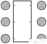
Fig. 11.1. Tripod gait. Initial position
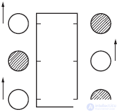
Fig. 11.2. Tripling walk, first step forward
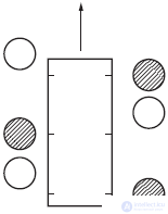
Fig. 11.3. Tripod gait, second movement, shifting center of gravity
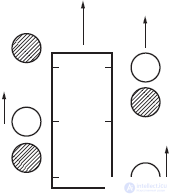
Fig. 11.4. Tripling, third movement
Create walking robot
There are many models of small winding walking toys. Such toy "pedestrians" move their legs up and down and back and forth with the help of cam mechanisms. Although such constructions are quite capable of “walking”, and some do it quite quickly, our goal is to create a walking robot that does not use cam mechanisms to simulate walking movements.
We will build a robot simulating a tripod gait. The robot described in this chapter requires three servomotors to move. There are other six-legged and four-legged models of walking robots that require large degrees of freedom in their legs. Accordingly, having more degrees of freedom requires more control mechanisms for each of the legs. If servomotors are used for this purpose, then two, three or even four engines will be required for each leg.
The need for so many servomotors (drives) is dictated by the fact that at least two degrees of freedom are required. One for lowering and raising the leg, and the other for moving it back and forth.
Walking robot with three servomotors
The walking robot, which we are going to make, is a compromise solution in design and construction and requires only three servomotors. However, even in this case, it provides movement with a tripod gait. In our design, three lightweight servos HS300 (torque 1.3 kgf) and a microcontroller 16F84-04 are used.
Device operation
Before we begin to design the robot, we will look at the finished robot shown in fig. 11.5, and analyze how the robot moves. A tripod walk, which is used in this design, is not the only possible one.
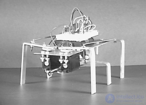
Fig. 11.5. Six-legged walker ready for a walk
In the front of the robot are fixed two servomotors. Each of the servomotors controls the movement of the front and rear legs on the respective side of the robot. The front leg is attached directly to the rotor of the servomotor and is able to swing back and forth. The back leg is connected to the front with a thrust. Traction allows the back leg to repeat the movement of the front leg back and forth. The two central legs are controlled by a third servomotor. This servomotor turns the central legs along the longitudinal axis at an angle from 20 ° to 30 ° clockwise and counterclockwise, which tilts the robot to the right or left.
Using information about the mechanism of the drive legs, we now see how our robot will move. Let's look at pic. 11.6. We will start from a resting position. Each circle marks the position of the foot. As in the previous case, dark circles indicate the position of the support legs. Note that in the resting position, the middle legs are not supporting. These legs are 3 mm shorter than the front and rear legs.
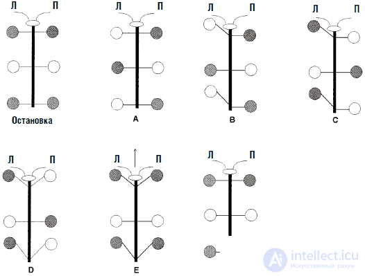
Fig. 11.6. Phases of motion hex
In position A, the central legs rotate clockwise at an angle of approximately 20 ° from the center position. This causes the robot to tilt to the right. In this position, the weight of the robot is held by the right front and back legs and the left central foot. This is the standard position of the "tripod", which was described above. Since the left front and left hind legs are “in the air”, they can be moved forward, as shown in Fig. 11.6, position B.
In the C position, the central legs rotate counterclockwise at an angle of approximately 20 ° from the central position. This causes the robot to tilt to the left. In this position, the weight of the robot is distributed between the left front and rear legs and the right middle leg. Now the right front and rear legs do not carry the load and can be moved forward, as shown in pos. D Fig. 11.6.
In position E, the central legs return to the middle position. In this position, the robot "stands" straight and relies only on the front and rear legs. In position F, the front and rear legs simultaneously move backwards, and the robot accordingly moves forward. Further the cycle of movement is repeated.
This was the first way of walking that I tried to reproduce, and this system works. You can develop, improve and design other models of ways of walking with which you can conduct experiments. I will leave to you the development of ways of going backwards (reversing) and turning right and left. I will continue to improve this robot by adding sensors for walls and obstacles, as well as ways to move backwards and turns.
Robot design
I took the sheet of aluminum with dimensions of 200x75x0.8 mm as the basis for the “body” of the robot. Servomotors are attached to the front of the plate (see fig. 11.7). Marking openings for servomotors should be copied from the drawing and transferred to a sheet of aluminum. Such copying will ensure the accuracy of the position of the mounting holes for servomotors. Four holes with a diameter of 4.3 mm are located slightly behind the midline and are designed for mounting the central servo motor. These four holes are offset to the right. This must be done so that the flange of the central servomotor is located exactly in the center of the “body”. The two rear openings are designed for mobile mounting of the rear legs.
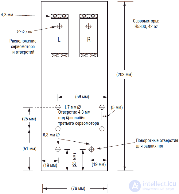
Fig. 11.7. Foundation of the "body"
To mark the centers of the holes for drilling it is necessary to use a center punch. Otherwise, when drilling holes, the drill may "lead". If you do not have a center punch, you can use a sharp nail as a good replacement.
The legs of the robot are made of aluminum strip 12 mm wide and 3 mm thick (see fig. 11.8). Four holes are drilled in the front legs. Two holes are drilled in the hind legs: one for mobile fastening and the other for attaching thrust. Note that the hind legs are 6 mm shorter than the front. This is because it is necessary to take into account the height of the servomotor flange, to which the front legs are attached, above the general level of the plate. Shortening the hind legs aligns the position of the platform.
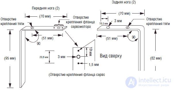
Fig. 11.8. The design of the front and rear legs
After drilling the required holes, bend the aluminum strip to the desired shape. Clamp the strip in a vice from the side of the drilled holes at a distance of 70 mm. Click on the plate and bend it at a 90 ° angle. It is best to press the plate directly near the vise jaws. In this case, the plate will bend at an angle of 90 ° without the risk of flexing the “lower” part of the leg.
The central legs are made of one piece of aluminum (see fig. 11.9). When attached to the robot, the central legs are 3 mm shorter than the front and rear legs. Thus, in the middle position, they do not touch the ground. These legs are designed to tilt the robot to the right and left. When the central servomotor rotates, the robot bends an angle of approximately ± 20 °.
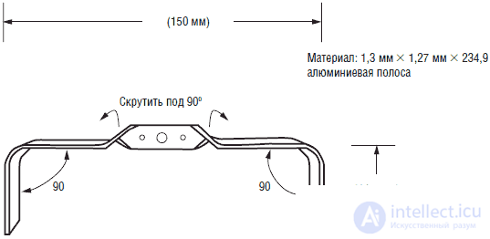
Fig. 11.9. Middle legs
In the manufacture of central legs in an aluminum strip measuring 3x12x235 mm, three central holes for the servomotor flange are drilled first. Then the aluminum strip is fixed in a vice, and the jaws of the vice on the upper edge should fix the strip at a distance of 20 mm from the center of the strip. Clamp the strip with pliers at a distance of approximately 12 mm from the top edge of the vice. While keeping the pliers clamp, gently twist the aluminum strip at a 90 ° angle. Perform the operation slowly enough, otherwise you can easily break the plate. Similarly twist the plate on the other side.
After the 90 ° twist is done, additionally bend the plate in two places by 90 °, as we did for the front and rear legs.
Installation of servomotors
The front servos are attached to the aluminum base with plastic screws and 3 mm nuts. I chose plastic screws, since they can be slightly bent and compensated for small discrepancies between the positions of the holes drilled in the plate and the mounting holes of the servomotor.
The legs are attached to the plastic flange of the servomotor. For this, I used 2 mm screws and nuts. When attaching the flange to the servomotor shaft, make sure that each leg can deviate back and forth at the same angle from the average perpendicular position.
Thrust design
The traction between the front and rear legs is made of a bar with a thread of 3 mm (see fig. 11.10). In the original design, the thrust length is 132 mm from center to center. The thrust is inserted into the holes on the front and rear legs of the robot and can be fixed with the help of several nuts.
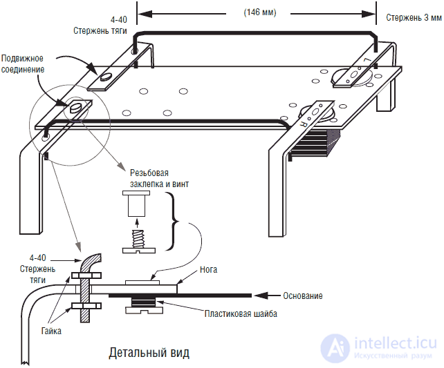
Fig. 11.10. Detailed drawing of the hinge and thrust
Before installing the robot's rear legs should be attached to the base. The hind legs are made from a 9.5 mm threaded rivet and a mounting screw. Detailed fastening of a leg is shown in fig. 11.10. It is necessary to put plastic washers under the base, which will fill the space between the bottom of the base and the screw head. This design provides the attachment of the legs to the base without her “hanging out”. To reduce friction, you can use plastic washers. Do not use too many washers - this will lead to excessive clamping of the legs to the surface of the base. The leg should turn in the joint fairly freely. In fig. 11.11 and 11.12 are photographs of a partially assembled six-legged robot.
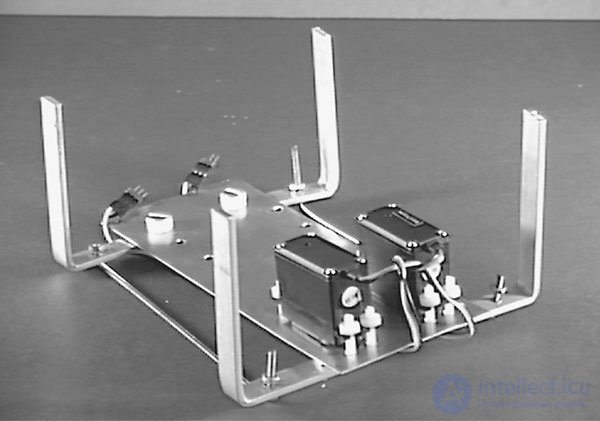
Fig. 11.11. Sheshinog - bottom view. Front two servomotors
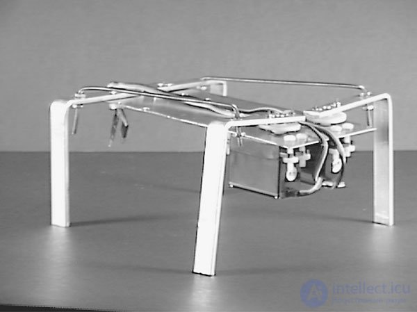
Fig. 11.12. Partially assembled six-legged with two front servos
Central servo motor
To mount the central servomotor, two L-shaped brackets will be required (see. Fig. 11.13). Drill the corresponding holes in the aluminum strips and bend them at a 90 ° angle to make the brackets. Attach the two L-shaped brackets to the central servomotor with plastic screws and nuts (see. Fig. 11.14). Then attach the center servo assembly to the bottom of the base. Align the four holes on the base with the holes on the top of the L-shaped brackets. Fasten parts with plastic screws and nuts. In fig. 11.15 and 11.16 are photos of the top and bottom view for a six-legged robot.
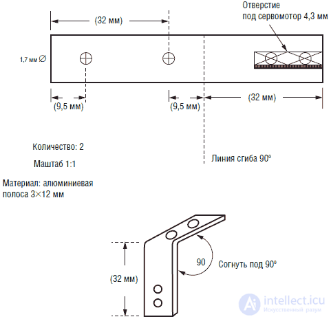
Fig. 11.13. Central servo bracket
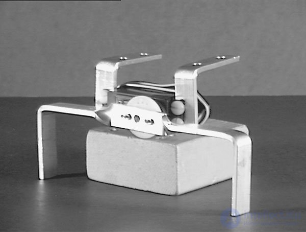
Fig. 11.14. Central motor assembly with mounting brackets and middle legs

Fig. 11.15. Sheshinog - bottom view with three servomotors
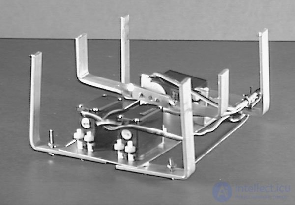
Fig. 11.16. Sixinog assembly. Design ready for electronic control installation
Electrical part
In fig. Figure 11.17 shows a control circuit for servomotors using a PIC microcontroller. The servos and microcontroller are powered from a 6 V battery. The 6 V battery compartment contains 4 AA cells. The microcontroller circuit is assembled on a small breadboard. The battery compartment and the circuit are attached on top of the aluminum base. Figure 11.5 shows the finished design of the robot, ready to "move".
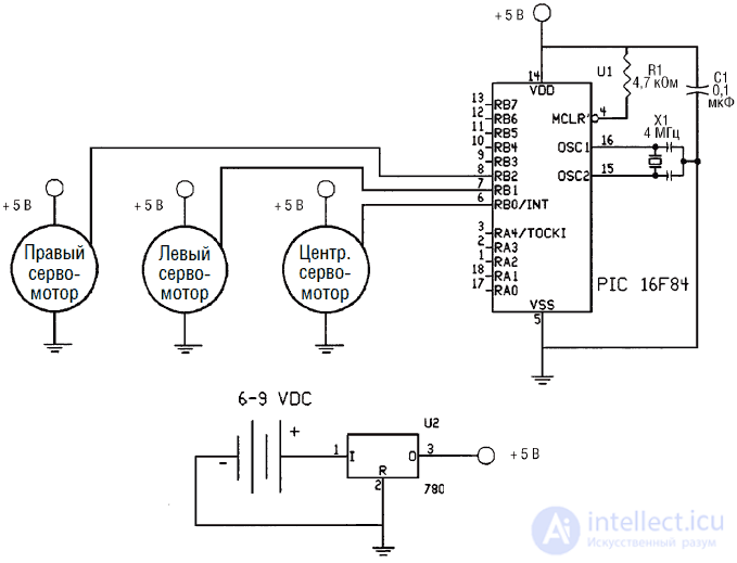
Fig. 11.17. The control circuit of the six-legged robot
Microcontroller software
The 16F84 microcontroller controls the operation of three servomotors. The presence of a large number of unused I / O buses and the space for the program provides an opportunity to improve and modify the basic model of the robot.
PICBASIC program
'Six-legged walking robot
'Connections
'Left Servo Pin RB1
'Right Servo Pin RB2
'Servo Tilt Pin RB0
'Move only forward
start:
for B0 = 1 to 60
pulsout 0, 155 'Tilt clockwise, raise the right side
pulsout 1, 145 'Left legs in place
pulsout 2, 145 'Right legs move forward
pause 18
next B0
for B0 = 1 to 60
pulsout 0, 190 'Tilt counterclockwise, lift the left side
pulsout 1,200 'Left legs move forward
pulsout 2, 145 'Right legs keep forward
pause 18
next B0
for B0 = 1 to 15
pulsout 0, 172 'Medium, no slope
pulsout 1, 200 'Left legs keep forward
pulsout 2,145 'Right legs keep forward
pause 18
next B0
for B0 = 1 to 60
pulsout 0, 172 'Medium, no slope
pulsout 1, 145 'Movement of the left legs back
pulsout 2, 200 'The movement of the right legs back
pause 18
next B0
goto start
Not all servos respond the same to the pulsout command. It is possible that to create a robot, you will acquire servos, the characteristics of which will differ slightly from those that were used by me. In this case, note that the parameters of the pulsout command, which determines the position of the rotor of the servomotor, must be adjusted. In this case, you need to select the numerical values of the parameters pulsout, which would correspond to the type of servomotor used in your design of a six-legged robot.
This program on PICBASIC allows the robot to move only in the forward direction, however, by slightly changing the program, the designer can force the robot to move backwards and make turns to the right and left. Installing multiple touch sensors can inform the robot of obstacles.
A list of details of the design of the walking robot
• Servomotors
• Microcontrollers 16F84
• Aluminum strips
• Aluminum sheet
• 3 mm threaded rods and nuts
• Plastic screws, nuts and washers

Comments