Lecture
This chapter discusses the class of robots that do not have a CPU based on a control circuit. Such robots operate on the principles of stimulus-response characteristic of neural networks.
The stimulus-reactive mechanisms used in robots carry a number of names, such as neural networks, behaviorally oriented schemes, neural organization schemes, and predicative architecture systems. The pioneer of these works is William Gray Walter, who created behavioral-oriented systems in the late 40s. Regardless of Walter's work, the robot response schemes built on the principles of neural networks were scientifically developed and improved by Valentino Breitenberg in the 1980s, which was reflected in his book: Mobile Devices: Synthetic Psychology Experiments. Inspired by the work of Walter, a professor at the Massachusetts Institute of Technology Rodney Brooks developed his own version of the response to stimuli, which he called "predicative architecture." In turn, Mark Tilden, inspired by the work done by Rodney Brooks, created the BEAM system of robots using "neural networks."
The topic of behavioral-oriented robots is very relevant now and will certainly be even more important in the future. In systems of such an architecture, stimulus-response mechanisms may be built one above the other. A device with a hierarchically multi-layered stimulus-response mechanism may exhibit a strikingly “intelligent” behavior, like a robot-hunter for “light”, described below.
Until a certain time, I will use the term “behaviorally oriented” to describe the “stimulus-response” mechanism. A behavioral-oriented approach is one of two main approaches to supplying robots with “intelligence,” as described in ch. 6. One of them is called “top down” intelligence, and the second is “bottom up” intelligence.
In order to introduce “intelligence” into the device controlling the functions of a mobile robot (using the term “function” I limit, for simplicity, the possible discussion area to the functions of motion and inspection of the surrounding space, but this is undoubtedly a valid limitation for using other approaches) which needs to be decided will be the most successful to complete the task. The intelligence that controls the operation of the device “from top to bottom” is an expert system or program for performing a given type of search and detection. The bottom-up approach relies on the creation of a system of artificial behavior of the robot, which determines its search actions.
At first glance, there is no significant difference between these two approaches, but there is one very important difference. If the expert system is in a situation (or external circumstances) not covered by the program, the robot will be in "indecision". On the other hand, a system of behavior that is not focused on finding patterned “programmed” situations for calculating response options does not attach “importance” to the surrounding circumstances — it simply continues the search.
Experimental work carried out for 30 years has shown that similar systems with the “intelligence” type are “bottom-up,” that is, behaviorally oriented, in some cases successfully coped with tasks when expert systems were defeated.
Pioneers in robotics
As already noted, one of the pioneers in the development of a behavioral-oriented approach (“bottom-up”) in robotics was William Gray Walter. He was born in Kansas City, Missouri in 1910. When he was five years old, his family moved to England. There he attended school and graduated from King's College, Cambridge in 1931. After graduation, he took up basic research in the field of neurophysiology, which he conducted in hospitals.
At the beginning of his career, Walter became interested in the work of the Russian physiologist I.P. Pavlova, famous for his research on the mechanisms of "stimulus-response", conducted on dogs. In his experiments, Pavlov rang the bell just before giving food to experimental dogs. After a while, the dogs reacted with saliva to the bell itself.
Another contemporary of Walter, Hans Berger, invented the electroencephalographic apparatus. During the visit of Walter to the laboratory of Berger, he proposed some improvements of the electroencephalograph. After reworking, the sensitivity of the device increased, and EEG curves with frequencies below 10 Hz were detected in the human brain.
Walter's study of the human brain led him to study the neural networks of the brain. Due to their exceptional complexity, biological neural networks turned out to be inaccessible for an accurate topological picture or reproduction. For this reason, he chose to study a separate neuron and its electrical analog. He sought to find out what type of behavior can be obtained in a system consisting of several neurons.
To answer this question in 1948, Walter built a three-wheeled robot that looks like a turtle. The size of the robot was 12 "in height and about 18" in length. What turned out to be surprising is that this robot used only two electric neurons and at the same time showed quite complex and interesting behavior. The first two robots were affectionately named Elmer and Elsie (Electro Mechanical Robot and Electro Sensitive (Light Sensitive)). After observing the complex type of behavior demonstrated by the robots, Walter renamed them Machina Speculatrix (reasoning machine).
Remember that in the 40s the transistor was not yet invented, therefore electron tubes were used in the electronic neurons of the robot. Since the electron tubes consume significantly more power than transistors, the original design contained large-sized batteries.
The nervous system or the system of reflexes of the robot consisted of two sensors connected to two neurons. One of the sensors was a photoresistance, and the other was a contact switch connected to the outer shell of the robot.
The three wheels of the robot were arranged in a triangle. The front steering wheel was equipped with a steering gear and at the same time could rotate 360 ° in one direction. In addition, a running motor was connected to the same wheel, ensuring the forward movement of the robot. Since the steering mechanism could be rotated to full 360 °, power was supplied to the drive motor through two slip rings mounted on the drive axis.
The photoresistor was also mounted on the axis of the steering wheel drive mechanism. This made it possible to automatically combine the axis of the photoresistor “look” and the direction of movement of the robot.
Four modes of operation
Even before the appearance of designs of robots - hunters for light, this robot demonstrated four modes of operation. It should be noted that in this design, both the undercarriage engine and the steering actuator engine were almost always included.
• Search. The surrounding space is poorly lit or in darkness. The reaction of the robot: the engine steering gear - full speed, running engine - half speed.
• Movement. Found light source. Robot reaction: the engine of the steering mechanism is disconnected, the driving engine - full turns.
• Blinding. Bright light. The reaction of the robot: the engine steering gear - half speed, running engine - reversing mode.
• Touch. A collision with an obstacle. The reaction of the robot: the engine steering gear - full speed, running the engine - reversing.
Observable behavior
In 1950, Walter wrote two articles for Scientific American (Imitation of Life, May 1950 and Machine that Learns, August 1951), and then a book called Living Brain (Norton, New York, 1963). The interaction between the neural system and the environment has generated unexpected and complex types of behavior.
In one experiment, Walter built a shelter where Elsie could go in and recharge her batteries. The shelter was equipped with a small light source, which was supposed to attract the attention of the robot to it as the batteries were consumed. The robot could go into the shelter and automatically recharge the batteries. After the charging process was completed, the robot could leave the shelter in search of new light sources.
In another experiment, Walter attached small light bulbs to the shell of each turtle. The robots demonstrated an interaction that reminded the observer of some type of social behavior. The robots danced around each other, occasionally approaching and then diverging, which resembled the communication of robots in the manner of ritual behavior or marking of territory.
Build Walter's tortoise
We can reproduce most of the functions of the famous Walter's tortoise. The program we use simulates the work of neurons used in the original design. For the manufacture of the chassis will need some plumbing work. Locksmith work will be greatly simplified using the following tools:
• Kerner. Used to apply recesses on a sheet of metal to facilitate drilling. If you do not mark the center of the hole using a center punch, the drill can easily “lead”. For marking, place the tip of the punch at the point of the intended hole. Hit with a hammer to apply a groove.
• Hand shears for metal. Used for cutting sheet metal. I would recommend a 75 cm scissors. The cutting process is similar to using ordinary scissors. Note: cutting metal is much more difficult than cutting paper.
• Vice . Used for fixing metal parts for drilling and bending.
• Drill
• Hammer
You can find these tools in almost any plumbing store. You can also find thin sheets of metal and aluminum strips necessary for the manufacture of the chassis.
I made the chassis from a rectangular aluminum strip with a section of 3x12 mm and a stainless steel sheet with a thickness of 0.6 mm. Stainless steel is worse treated than conventional cold rolled sheet, so the next time I would prefer aluminum or rolled.
Running and turning enginesThe propulsion engine is an engine with a 100: 1 gearbox (see Fig. 8.1). I like this engine because it has a bracket. For a rotary engine, I used a standard servo motor with a force on the shaft of 1.3 kgf. The chassis will require three pieces of sheet metal.
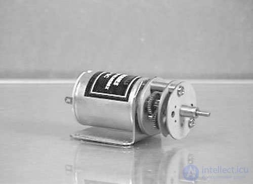
Fig. 8.1. 1.5–3 V DC motor with 100: 1 gearbox
The propulsion engine and the front wheel are fixed on the U-shaped channel (see. Fig. 8.2). U-shaped channel is made of steel strip with dimensions of 25 mm by 125 mm and a thickness of 0.4 mm. Three holes should be drilled in the center of the strip to fix the servo motor flange. The diameter of the central hole (3 mm) is larger than the diameter of the extreme holes (1.5 mm). Disconnect the flange from the servomotor by turning the center screw and pulling the flange up. Place the flange on the channel bracket and mark the positions of the central and side holes. Drill three holes. Attach the flange to the servomotor and tighten the center screw. For the extreme holes, use screws with nuts with a diameter of 3 mm. Drill three 3.1 mm holes for lateral mounting of the L-shaped bracket of the drive motor. Drill two coaxial holes with a diameter of 3 mm for mounting the front wheel.
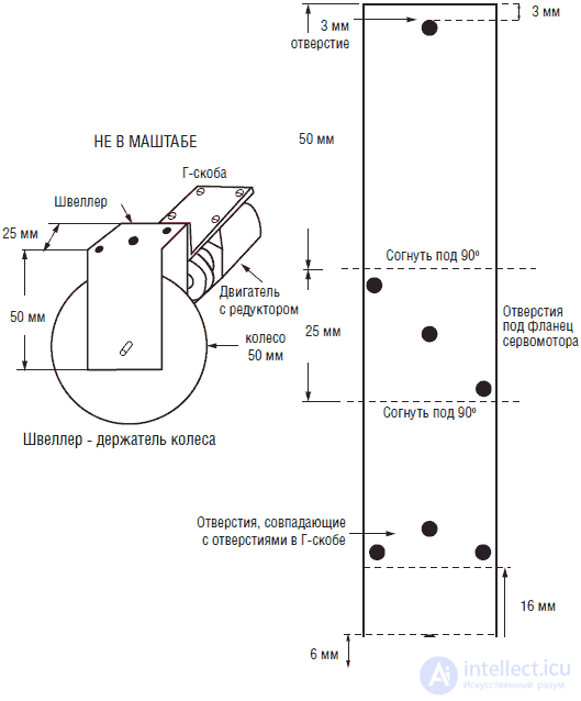
Fig. 8.2. U-shaped mounting bracket drive wheel
Clamp the strip in a vice and bend its ends at a 90 ° angle to form a U-shaped bracket.
Use the L-shaped bracket to attach the outboard engine to the U-shaped channel (see. Fig. 8.3). Dimensions L-shaped bracket 38x76 mm. Mark the holes on the plate according to the position of the corresponding holes on the gearbox housing. Make sure that the three holes on the L-shaped bracket correspond to the holes on the U-shaped channel bar.
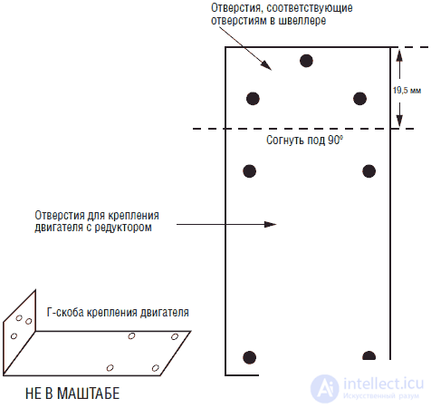
Fig. 8.3. L-shaped bracket mounting gear to the P-bracket
In fig. 8.4 shows a drawing of the base with the image of the position of the servomotor with a torque of 1.3 kgf. The dimensions of the base are 76x140 mm. Based on the power supply and electrical circuit will be mounted. To cut a hole under the servomotor, use the drawing.
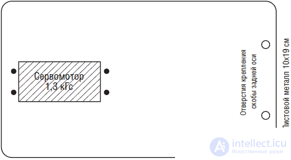
Fig. 8.4. Drawing of the base of the construction with a servo motor cutout with a torque of 1.3 kgf and holes for the rear axle mounting bracket
First drill four holes with a diameter of 3 mm along the edges of the rectangle. Then drill holes on the sides of the rectangle. This method is significantly easier than cutting or "biting" the metal around the perimeter of the required hole. After drilling the hole for trimming the edges, you can use nippers. The final processing of the edges is done with a file, after which you can mount the servomotor. Drill two holes at the back for attaching the rear axle bracket.
The drawing of the rear axle bracket is shown in Fig. 8.5. It is made of aluminum strip with dimensions 3x12x250 mm. Drill four holes 3 mm in diameter in the aluminum strip before folding. For the rear axle, I used wire from clothes hangers.
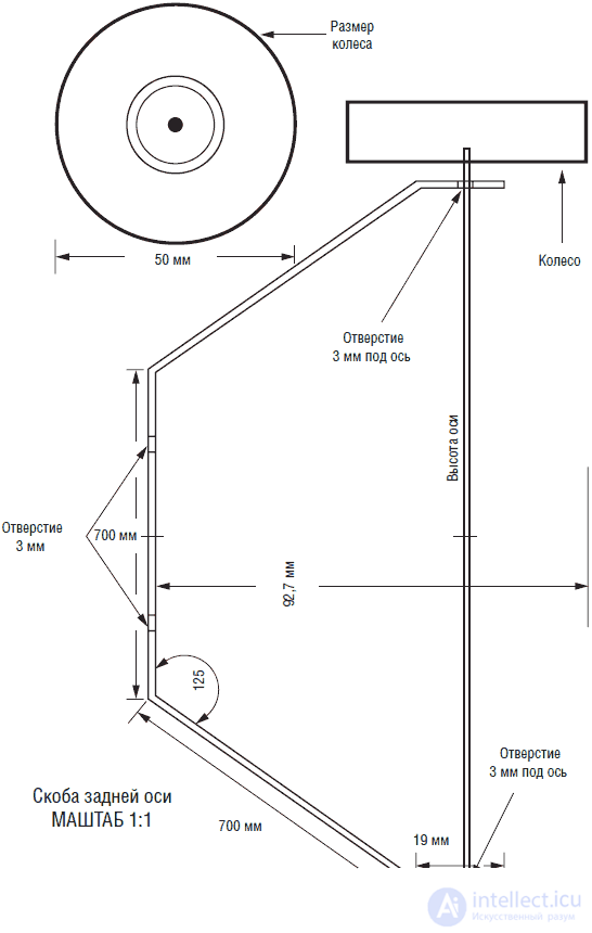
Fig. 8.5. Rear Axle Bracket
Then we have to fix the front wheel drive on the axis of the gear motor gearbox. I used a rubber wheel that sits on the axle with a friction of 3 mm, and the shaft diameter of the 100: 1 gear motor is 2 mm.
To solve this problem, I planted on a 75 mm axis a piece of a hollow metal tube with an outer diameter of 3 mm. I used a slotted screwdriver and a hammer to fit a 3mm tube onto a 2mm shaft. In order not to damage the gears of the gearbox, I put the shaft with a tube mounted on it on a smooth metal surface. Then, putting the screwdriver's tip on the tube, with a careful blow of the hammer on the screwdriver, squeezed the tube slightly, which should ensure good adhesion between the shaft and the tube. To reliably eliminate slippage, it is enough to flatten the tube in two or three places.
If you look closely at the gearbox shaft, you can see a flat groove on the shaft surface. If you gently flatten the tube along the groove, then you can achieve a very secure tube.
The drive wheel is simply put on a 3 mm tube. The friction between the wheel and the axle is enough for the wheel to rotate and move the robot without slipping. If you want to permanently fix the wheel on the axle (which I usually do not do), then it is enough to dissolve some epoxy glue and put it on the axle before putting on the wheel.
BalancingWhen the undercarriage is fixed on one side of the U-shaped bracket, it will unbalance the structure with its weight. For its balancing it is necessary to fix from 100 to 125 g of lead on the opposite side of the bracket. I used lead pieces 3 mm thick, which I used to store radioactive isotopes. Cutting and drilling of lead is not difficult. It is clear that for balancing you can attach any suitable heavy object (as is done in the washing machine drum).
ShellIn the original design of the robot turtle was used transparent plastic shell. The shell was connected to a switch that, when triggered, switched the robot circuit to “runaway” mode. I tried several types of designs, but I was not satisfied with them. In the end, I had no choice but to create my own shell.
Instead of making a solid shell, I made a bumper encircling the robot. The bumper is made of an aluminum strip with dimensions 3x12x810 mm (see fig. 8.6). The center of the strip and each bend are marked with a pencil. The strip must be clamped in a vice and bend in the required places at the desired angle. The two ends of the strip converge at the rear of the bumper. These ends are fastened together using a length of 3x12x25 mm strip. In each of the ends of the strip is drilled a hole with a diameter of 3 millimeters. The corresponding holes are drilled at the ends of the bumper. The strip is fastened to the bumper with two 3-mm screws with nuts (see. Fig. 8.7).
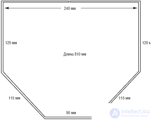
Fig. 8.6. Dimensions of the bumper bent from aluminum strip 3x12x815 mm
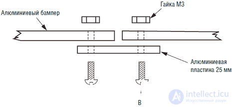
Fig. 8.7. A detailed view of a part of the aluminum strip at the junction of the ends of the bumper.
To attach the bumper to the robot, the upper bracket is used, repeating the dimensions and shape of the front part of the bumper (see Fig. 8.8). The top bracket is made of aluminum strip with dimensions of 3x12x370 mm. Similarly to the bumper, the center of the strip and the places of the required bends are marked with a pencil. The strip bends in a vice in the same way as a bumper.
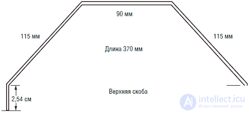
Fig. 8.8. Side view of the upper bracket, made of aluminum strip 3x12x370 mm
It is very important to find the line of the center of gravity of the bumper, since it will be the best place to attach the upper bracket. Put the bumper on the end of the aluminum strip. Move it in different directions until you find the equilibrium position. Mark in pencil the corresponding places on the sides of the bumper. Drill a hole with a diameter of 3 mm on each side. Drill the corresponding holes at the ends of the upper bracket. Attach the top bracket to the bumper with 3mm screws and nuts.
Mount the bumper to the base of the robot designThe bumper is attached to the “body” of the robot using the upper bracket. Drill three holes with a diameter of 3 mm in the upper part of the bracket. One hole is drilled in the center; the other two at a distance of 28 mm from the center (see fig. 8.9). Three corresponding holes must be drilled at the base of the robot behind the servomotor. The position of the holes should be chosen in such a way that the gap between the bumper and the rear wheels lies within the range of 3-6 mm. The position of the corresponding center hole in the base should be moved forward approximately 6 mm.
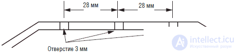
Fig.8.9. Side view of the location of the holes in the horizontal part of the upper bracket
Скоба крепится к основанию при помощи двух 3-миллиметровых винтов длиной 25 мм, четырех гаек 3 мм, и двух пружин длиной 25 мм, внутренним диаметром 3 мм и усилием натяжения порядка 900 г (см. рис. 8.10). Жесткость крепления бампера может быть отрегулирована затягиванием или отпусканием крепежных гаек. После установки бампера, при касании или столкновении робота с препятствием бампер будет отклоняться назад и замыкать контакты выключателя.
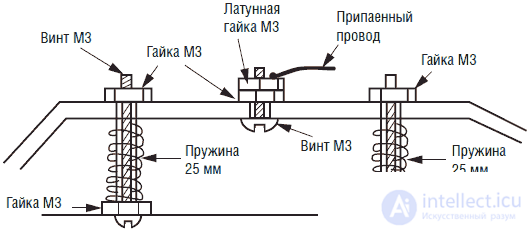
Fig. 8.10. Боковой вид крепления верхней скобы к основанию робота при
Для изготовления выключателя использованы центральные отверстия в верхней скобе и основании робота. As can be seen from fig.8.10, a 3 mm screw, tightened with a conventional galvanized nut and an additional brass locknut, is inserted into the central hole of the bracket. A contact wire is soldered to the brass nut. This design provides reliable electrical contact between the wire and the bumper bracket. Brass nut is used because it is easy to solder the conductor to it. Conventional galvanized nuts are difficult to solder, which reduces the reliability of electrical contact.
The other half of the switch consists of a plastic screw of 3 mm length 25 mm and three nuts, one of which is brass and to which the second contact wire of the switch is soldered (see. Fig. 8.11). In fig.8.12 is a drawing of the switch assembly. The adjustment of the switch is to position the lower contact brass nut directly below the upper aluminum bracket, but without touching each other. When the upper bracket leans forward, it touches the brass nut, thus closing the electrical contact.
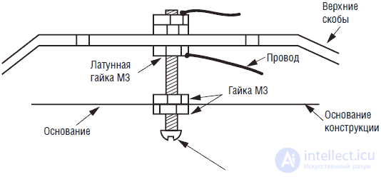
Fig.8.11. Side view of the touch sensor (half of the sensor on the base of the robot), plastic screw with brass nut top
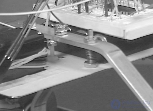
Fig. 8.12. Detailed photo of mounting the sensor "touch" and the spring suspension of the upper bracket
In my prototype of the device, CdS photoresistors with a dark resistance of about 100 kΩ and a light resistance of about 10 kΩ are used. The best place to fix the photoresistors is the upper part of the 100: 1 gearbox of the traveling motor (see. Fig. 8.13). To attach the photoresistors, I used a small plastic plate fixed at an angle of 45 ° upwards and a light-proof visor placed between the photoresistors (see. Fig. 8.14). Fixing photoresistors on the front wheel platform automatically ensures that the direction of reception of light radiation coincides with the direction of motion. This type repeats the design of the original turtle robot.
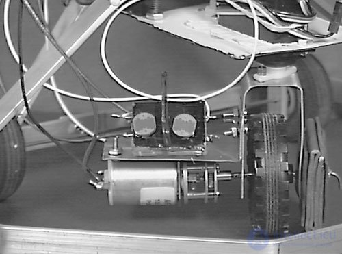
Fig.8.13. Detailed photograph of the design of the front-wheel drive assembly, containing the counterweight, drive wheel, motor with gear and illumination sensors
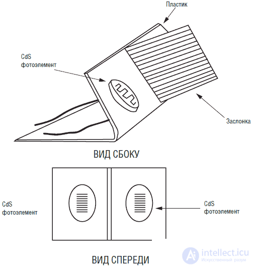
Fig.8.14. Isometric view of the sensor unit
The use of two CdS photoresistors greatly simplifies the calculations necessary to solve the problem of following the light source. This requires an algorithm similar to the algorithm of the device for tracking the direction of the light source, described in Ch. 6. The operation of the photoresistors block is illustrated in Fig. 8.15. When both sensors are illuminated in the same way, their resistances are approximately equal. If the difference between the readings of each sensor does not exceed ± 10 units, the PIC program considers them to be equal and does not give a command to the rotation device. When one of the sensors enters the shadow of the light source, the resistance difference exceeds ± 10 units. Accordingly, the PIC microcontroller includes a turning device to ensure equal illumination of the sensors. At the same time, the front wheel turns, and the robot moves directly to the light source.If the illumination exceeds the threshold, the robot enters the "avoidance" mode.
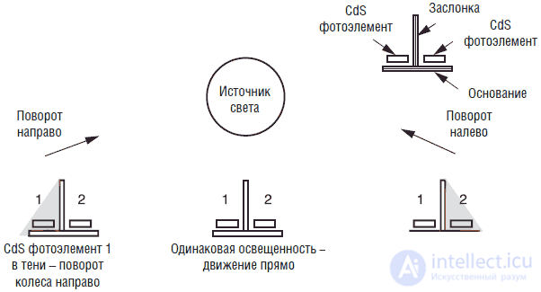
Fig. 8.15. Функциональное реагирование блока датчиков
Принципиальная схема робота изображена на рис. 8.16. «Интеллект» робота обеспечивается работой двух микроконтроллеров PIC16F84. Сигнал для управления рулевым механизмом сервомотора снимается с шины RB3 PIC микроконтроллера 2. Ходовой двигатель с редуктором 100:1 соединен с мостовой схемой, состоящей из компонентов Q1-Q4, D1-D4 и R1-R4. Мостовая схема управляется с шин входа/выхода RB1 и RB2. Показатели световых CdS датчиков считываются шинами RB6 и RB7 микроконтроллера 1. Показания датчика касания считываются шиной RB5, что сигнализирует о наличии препятствия. Монтаж устройства я осуществил на двух небольших макетных платах без применения пайки. Макетные платы закреплены на основании робота на крышке батарейного отсека.
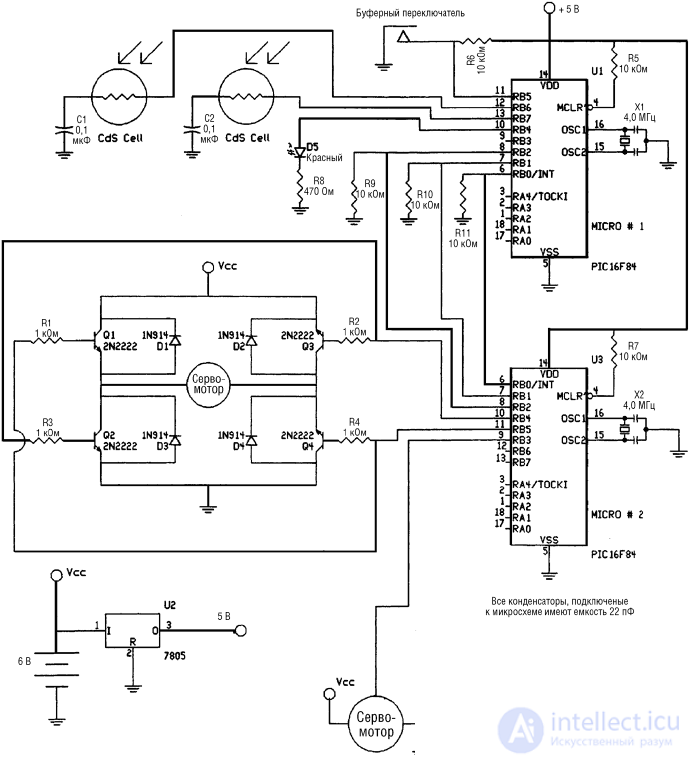
Fig. 8.16. Electrical circuit diagram of a robot turtle
Для точного моделирования функций исходной конструкции (точного повторения поведения оригинального робота-черепахи конструкции Вальтера) необходимо два микроконтроллера. Распределение вычислительных функций между двумя процессорами обеспечивает более четкую и слаженную работу робота.
The main reason for using the second microcontroller is the task of controlling the servo steering mechanism. The power of one microprocessor was not enough to read the readings of two CdS photoresistors and simultaneously control the steering mechanism. If I used a conventional motor with a gearbox for taxiing, then one microprocessor would be enough. If you look at things optimistically, the advantage of this approach to solving a problem is the possibility of creating a robot with two processors working in pairs (that is, time-sharing systems).
Одному микроконтроллеру, названному микроконтроллером 1, я назначил функции отслеживания направления источника света и контроля датчика столкновений. Управление двигателями хода и поворота обеспечивается вторым микроконтроллером, имеющим номер 2. Чтобы схема работала, необходимо обеспечить связь между микроконтроллерами. В данном случае двухсторонняя связь не требуется: один микроконтроллер подает управляющие сигналы, а второй – «слушает».
Микроконтроллер 1. Микроконтроллер 1 считывает информацию со световых CdS датчиков и с датчика столкновений. Его связь с микроконтроллером 2 осуществляется с помощью трех шин ввода/вывода.
• Шина ввода/вывода 1 отображает состояние CdS датчика 1. Если сила света, попадающего на CdS 1 больше, чем на CdS 2, то на шине появляется сигнал низкого уровня. Если сила света на обоих датчиках равна, то на выходе присутствует сигнал высокого уровня.
• Шина ввода/вывода 2 отображает состояние CdS датчика 2. Если сила света, попадающего на CdS 2, больше, чем на CdS 1, то на шине появляется сигнал низкого уровня. Если сила света на обоих датчиках равна, то на выходе присутствует сигнал высокого уровня.
• Шина ввода/вывода 3 отображает либо состояния датчика столкновений, либо слишком большую засветку CdS датчиков. В обоих случаях на выходе появляется сигнал высокого уровня.
Микроконтроллер 2. Микроконтроллер 2 проверяет состояние трех шин ввода/вывода и на основании полученной информации управляет движением и поворотом согласно таблице:
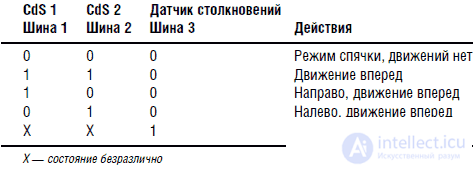
Соответственно шины 1 и 2 отражают состояние датчиков CdS, а шина 3 – состояние датчика столкновений.
Добавление состояния «спячки»Я добавил состояние «спячки», соответствующее общему низкому уровню освещенности. Если оба CdS датчика освещены примерно одинаково, то робот движется вперед. Если датчики освещены в разной степени, то робот поворачивается соответственно направо или налево. Если поступает слишком много света или срабатывает датчик столкновений, то робот переходит в режим избегания.
NutritionБатарейный отсек робота содержит четыре элемента АА, обеспечивая напряжение питания 6 В. При проверке функционирования робота есть основания предполагать, что истощение батарей происходит достаточно быстро.
Program
Блок-схема программы изображена на рис. 8.17. После включения питания ходовой двигатель отключен, и микроконтроллер начинает искать наиболее яркий источник света, поворачивая сервомотор. Если источник света имеет слишком большую яркость, то включается режим избегания. В режиме избегания ходовой двигатель включается в режим реверса; при этом ведущее колесо поворачивает направо или налево. Если освещенность не достигает уровня режима избегания, то робот поворачивается в направлении источника света и движется вперед. При замыкании датчика столкновений робот предполагает наличие препятствия и переходит в режим избегания. При выключении датчика столкновения (препятствия нет) программа переходит на начало, и процесс поиска и движения к наиболее яркому источнику света продолжается.
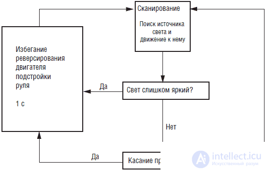
Fig. 8.17. Блок-схема программы
Программа написана для компилятора PICBASIC и введена непосредственно в PIC16F84. Без особых изменений программа может быть написана на версии PICBASIC Pro. Программа может быть подстроена под имеющиеся экземпляры CdS датчиков, используемых двигателей и т. п.
Программа 1
'Микроконтроллер 1
start:
High 4: low 4 'Мигание светодиода
b7 = 0
button 5,0,255,0,b7,1,avoid 'Проверка препятствия
pot 7, 255, b0 'Считывание датчика CdS 1
pot 6, 255, b1 'Считывание датчика CdS 2
if b0 <= 250 then skip 'Dark enough?
If b1> = 250 then slp 'Yes
skip: 'No
if bo> 25 then skip 2 'Too much light
if b1 <25 then avoid 'Yes
skip2: 'No
If bo = b1 then straight 'The illumination is the same, forward
If bo> b1 then greater 'Check light
if bo <b1 then lesser 'Check Illumination
straight:
high 0: high 1: low 2 'Message to microcontroller 2
goto start 'Go straight
greater:
b2 = b0 - b1 'Check the difference in light
if b2> 10 then rt 'If more than 10, turn right
goto straight 'If not, go straight
lesser:
b2 = b1 - b0 'Check the difference in light
if b2> 10 then lt 'If more than 10, turn left
goto straight 'If not, go straight
rt: 'Turn right, sending
high 0: low 1: low 2 'Message to microcontroller 2
goto start
lt: 'Turn left, parcel
low 0: high 1: low 2 'Message to the microcontroller 2
goto start
slp: 'Hibernation mode, sending
low 0: low 1: low 2 'Message to microcontroller 2
goto start
avoid: 'Avoidance mode, sending
low 0: low 1: high 2 'Message to the microcontroller 2
goto start
Program 2
'Microcontroller 2
b4 = 150 'Setting the middle position of the servomotor
start:
peek 6, b1 'Reading microcontroller data 1
let b0 = b1 & 7 'Masking except the first three bits
if b0 = 0 then slp 'hibernation time
if b0 = 1 then rt 'Turn right
If b0 = 2 then lt 'Turn left
if b0 = 3 then fw 'go straight
if b0 = 4 then avoid 'Avoidance mode
goto start
slp:
low 4: low 5 'Shut down engine
pulsout 3, b4 'Start servo
pause 18 'Servom Turn On Delay
goto start 'Reading microcontroller data 1
rt: 'Turn right
high 4: low 5 'Moving Forward
if b4> 200 then rt1: 'Turn right is maximal
b4 = b4 + 1 'No
rt1: 'yes
pulsout 3, b4 'servo rotation
pause 18 'Delay (55 Hz)
goto start 'Reading microcontroller data 1
lt: 'Turn left
high 4: low 5 'Moving Forward
if b4 <100 then lt1: 'Turn left max.
b4 = b4 - 1 'No
lt1: 'yes
pulsout 3, b4 'servo rotation
pause 18 'Delay (55 Hz)
goto start 'Reading microcontroller data 1
fw: 'Straight
high 4: low 5 'Go straight
pulsout 3, b4 'servo rotation
pause 18 'Delay (55 Hz)
goto start 'Reading microcontroller data 1
avoid:
low 4: high 5 'Backward movement
if b4> 150 then vr 'Check. Turning right?
If b4 <= 150 then vl 'Check. Change directions to the left?
vr: 'Reverse to right
b5 = b4 - 30 'direction of rotation
for b6 = 1 to 120 'Delay cycle 2 s
pulsout 3, b5 'servo rotation
pause 18 'Delay (55 Hz)
next b6 'End of cycle
goto start 'Reading microcontroller data 1
vl: 'Change directions to the left
b5 = b4 + 30 'Turning direction
for b6 = 1 to 120 'Delay cycle 2 s
pulsout 3, b5 'servo rotation
pause 18 'Delay (55 Hz)
next b6 'End of cycle
goto start
A photograph of the robot assembly is shown in Fig. 8.18
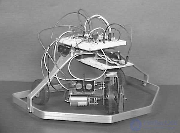
Fig. 8.18. Front view of the finished structure
Behavior
For normal operation of the robot, a sufficiently low total illumination is needed, against the background of which one bright light source stands out. My robot needed such a low level of general illumination that I had to make two small light filters from colored plastic in order to reduce the flow of light entering the CdS photocells.
The prototype robot demonstrates the following behavior. With uniform illumination (there is no separate bright source), the robot moves in a straight line or describes circles, depending on the presence of bright sources at previous points in time. With too much general illumination, it rolls back. If there is a source of medium intensity, then it “finds” it and moves directly towards this source.
The program can be improved to study more interesting and exotic types of behavior. Before doing this, let's see how the standard program works. Program 1 of the microcontroller 1 initially polls the sensors and sends information to the microcontroller 2. In this program, you can change the sensitivity of the sensors to adapt to the existing sensor. To do this, you need to change the lines:
if b0 <= 250 then skip 'Dark enough?
If b1> = 250 then slp 'Yes
skip: 'No
The maximum value of the sensor readings can be equal to 255 (total darkness). This value can be increased to raise the average level of illumination for “hibernation”.
The level of illumination required to enable avoidance mode can be changed using the lines:
if bo> 25 then skip 2 'Too much light
if b1 <25 then avoid 'Yes
skip2: 'No
Increasing the value, which in this case is equal to 25, will reduce the level of illumination at which the robot will go into the avoidance mode. In turn, reducing the numerical value will increase the light intensity for the avoidance mode. In most cases, you will want to reduce the numerical value of the parameter. However, I would not advise reducing it below 9, because even in the full saturation mode, the resistance of CdS photocells never drops to zero. My test showed that the resistance at full saturation does not fall below 5 units.
The threshold difference between the readings of the two CdS photoresistors can be increased or decreased by changing the corresponding parameter in the greater and lesser procedures.
greater:
b2 = b0 - b1
if b2> 10 then rt
goto straight
lesser:
b2 = b1 - b0
if b2> 10 then lt
goto straight
In addition to this, it is possible to create a preferential direction of rotation of the robot (right- or left-handedness) by changing the parameters of the procedures greater and lesser, but not both at the same time. This means that the robot will turn in one direction more “readily” than in the other. For example, if we replace the line if b2> 10 then lt in the lesser procedure with if b2> 15 then lt, then our robot will turn to the right more readily.
The design of the robot provides many opportunities for experimenters in the field of robotics, both in terms of the design itself and its software.
List of components for Walter's robot-turtle
• (1) 300x300 mm metal sheet 0.4–0.6 mm thick
• (1) 3x 12x 300 mm aluminum strip
• (1) servomotor with a torque of 1.3 kgf
• (1) motor with gearbox 1: 100
• screws and nuts 3 mm
• screws and nuts 2 mm
• (1) 3x 12x 810 mm aluminum strip
• (1) 3x 12x 370 mm aluminum strip
• (1) 3x 12x 50 mm aluminum strip
• (1) standard servo motor with a torque of 1.3 kgf
• (1) DC motor with 100: 1 gearbox
• (1) 51 mm drive wheel under the axle 3 mm
• (1) tube (steel, brass) outer diameter 3 mm, inner diameter 2 mm
• (2) CdS photoresistor, dark R - 100 kΩ, light R - 10 kΩ
• (4 Q1-Q4) NPN 2N2222 transistor
• (4 D1-D4) 1N914 diode
• (1 D5) LED red
• (4 R1-R4) 1 kΩ resistor, 0.25 W
• (6 R5-R7, R9-R11) 10 kΩ resistor, 0.25 W
• (1 R8) 470 Ohm, 0.25 W resistor
• (4) 22 pF capacitor
• (2 C1, C2) 0.1 μF capacitor
• (2 X1, X2) 4 MHz crystal resonator
• (1 Q5) voltage regulator 7805
• (2 IC1, IC2) microcontroller PIC16F84-04
• Accessories: screws 3 mm, plastic screws 3 mm long 25 mm, brass nuts 3 mm, springs 25 mm long (force 800 grams)
Suppliers
• Aluminum strips, screws, tubes, springs can be purchased at the respective stores.
• Servomotors can be purchased in specialized stores or ordered from distributors.
• A PIC microcontroller and front drive wheel can be ordered from Images Company.
Images Company
39 Seneca Loop
Staten Island, NY 10314
(718) 698-8305
Jameco
1355 Shoreway Rd.
Belmont, CA 94002
(650) 592-8097
Jdr
1850 South 10 St.
San Jose, CA 95112
(800) 538-5005
Build a Light Hunter Robot
We'll see if we can design a light hunter robot with some kind of “intellectual” behavior. In Chapter 6, we have already considered the tracking system for a light source on photoresistors. The tracking system fixed the light source and turned in its direction. When we placed the tracking system on a copy of the robot-turtle Walter, she directed the movement of the robot to the light source. We will call this type of “tentative” behavior the first level of the “stimulus-response” system.
The program illustrates how algorithmically controlled microcontrollers can simulate the functions of neurons. For the severity of the example, we present a neural circuit that performs the same functions without the participation of an algorithmically given “intelligence”.
In fig. Figure 8.19 shows the use of a dual balanced op amp with unipolar power. Two opamps are included in the comparators. We considered the comparator in detail in ch. 5. If you have any questions about pic. 8.19, reread ch. 5. Two CdS photoresistors are connected in series and form a voltage divider. The output of this photoresistive divider is connected to the inverted input of one opamp and the non-inverted input of another.
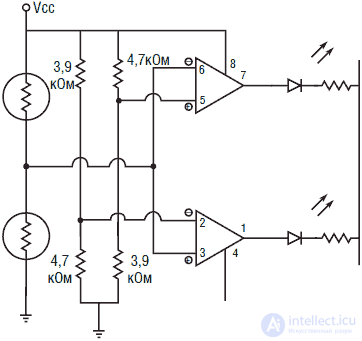
Fig. 8.19. Neural comparator on two op amps
Two more voltage dividers will be required. Structurally, they are mirror symmetrical. One divider is made up of a 3.9 kΩ resistor connected to a PI and a 4.7 kΩ resistor connected to ground. In the second divider, resistors of the same ratings are used, but in the reverse connection.
When both photoresistors are lit in the same way, none of the LEDs is on. If you cover one of the photoresistors, the corresponding LED will light up.
Each of the OU functions as a single electronic neuron. When the value of the electrical stimulus exceeds or falls below a predetermined threshold (depending on which of the OS you are considering), which is determined by the corresponding resistive divider 3.9 kΩ and 4.7 kΩ, the “neuron” is activated. The activation of a neuron (i.e. a signal at the output of an opamp) can be used to turn on a DC motor through an NPN transistor (see fig. 8.20). In turn, the engines can provide the movement and direction of movement of the robot hunter.
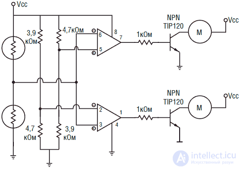
Fig. 8.20. DC motor control using neural comparator
For the manufacture of a simple robot hunter was used chassis, which has two DC motors with gearboxes (see. Fig. 8.21). When both engines are turned on, the robot moves forward in a straight line. If one of the engines is turned off, the other engine turns the structure to the right or left.
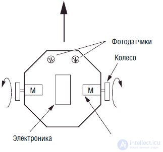
Fig. 8.21. The general scheme of the robot - svetookhotnika
For our robot hunter with the same illumination of the photoresistors, we need to supply power to both engines. To do this, between the output of each of the OS and the NPN base of the transistor, you must turn on the inverting buffer stage (see. Fig. 8.22).
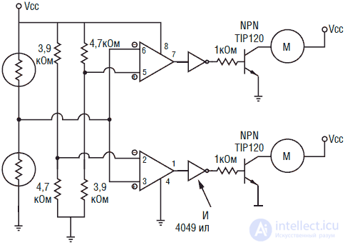
Fig. 8.22. DC motor control using neural comparators with inverters
Behavior
When one of the photoresistors drops less light than the other, one of the motors turns off accordingly, and the other motor turns the device in the direction of the light source. When the light fluxes are compared, both engines are turned on and the robot moves directly towards the light source.
Light avoidanceIf we swap the OU outputs that control the motors, then the behavior will change to the opposite. Instead of moving towards the source of light, the robot will avoid the light and seek "refuge".
Additional behavior type (nutrition)
We can complicate the behavior of a robot hunter by adding another level of "stimulus-response" (see. Fig. 8.23). For this purpose, another light-controlled comparator circuit will be suitable, which will provide the “power” type of behavior. Let me remind you that the principle of operation of the comparators was set forth in Ch. 5. If you have any questions about pic. 8.23, then read this chapter again. The second layer is built on top of the first. When the intensity of the light flux reaches a critical value, the reference detector removes the voltage from the circuits of the first layer and the engine power supply system. If we place a solar battery and a diode on the structure, the voltage generated by the battery will recharge the NiCd battery a little. We call this function "power."
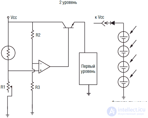
Fig. 8.23. Comparator scheme for the behavior of the type "food"
Another type of behavior (rest)
It is clear that we have no desire for the robot hunter to move in the dark, while losing precious energy. Therefore, we will add another layer of behavior. The third layer will be another threshold detector (see. Fig. 8.24). This detector disconnects the voltage from the circuits of the first layer, the engine power supply system and the circuits of the second layer at an illumination level close to the dark. With an increase in the average level of illumination, the system restores the power of the first layer, supplies voltage to the motors and circuits of the second layer.
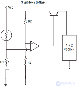
Fig. 8.24. Comparator pattern for rest type behavior
New type of behavior
Let's look at the behavior of the robot hunter according to the three-level (three-layer) “stimulus-response” scheme and see if this behavior can be classified as “reasonable”. In complete darkness, the robot is stationary, concentrating all activity on layer 3. With an increase in the level of illumination, layer 3 induces switching on the power of the two lower layers and activates the power to the engines. At this stage, layer 1 intercepts control of the device and directs the actions of the robot. The robot searches and moves towards the light source. As you move to the light source, the light level increases. When the illumination reaches a critical threshold, Layer 2 circuit will turn off the power to the engines, putting the robot into “power” mode, which will allow it to “feed” (recharge the batteries) using a solar battery.
Whether you decide to consider this behavior reasonable or not depends on your personal preference. Such questions are discussed "on both sides of the barricades." In the end, such a device illustrates the fact of how complex the behavior can be when using a hierarchically level system of building a “stimulus-response” type.
BEAM Robotics
The ideology of BEAM robotics was proposed by Mark Tilden while working at the University of Waterloo in Canada. Interest in the BEAM style robots arose in Mark after a lecture given by Rodney Brooks at the Massachusetts Institute of Technology, which Mark attended in 1989. Professor Rodney Brooks considered the approach to the design of robots as a system of "stimulus-response" type, called "predicative architecture."
The abbreviation BEAM (in Russian BEAM) is a multi-valued acronym that has something to do with issues of biology, electronics, aesthetics and mechanics. I said “some attitude,” since this acronym can be interpreted, for example, as Biotechnology, Evolution, Analog Systems, and Modular Principles.
Competitions BEAM robots
For designers of BEAM robots, competitions on the Olympic system are held annually, the program of which includes 14 points. The tradition of similar BEAM games began with the first international competitions held in Glasgow, Scotland, in 1990. The main idea of the BEAM-robotics philosophy is the evolution of robots: the development from simple designs to complex systems. An example is the idea of abandoning conventional schemes for building a robot controlled “from above” using a CPU in favor of bottom-up behaviorally oriented stimulus-response systems built on a hierarchically “layer” principle (neural networks, nerve fiber systems). Mark Tilden called similar stimulus-reactive constructs a “nervous network.”
Tilden has developed several interesting robot designs (see Figure 8.25). They use nerve networks modeled on transistors. Since Mark Tilden patented schemes of such nerve networks, it is not possible to find publications of such schemes in the open press. For this reason, I can not present you with samples of such schemes. Nevertheless, among the works of Tilden there is a book "Living Machines".
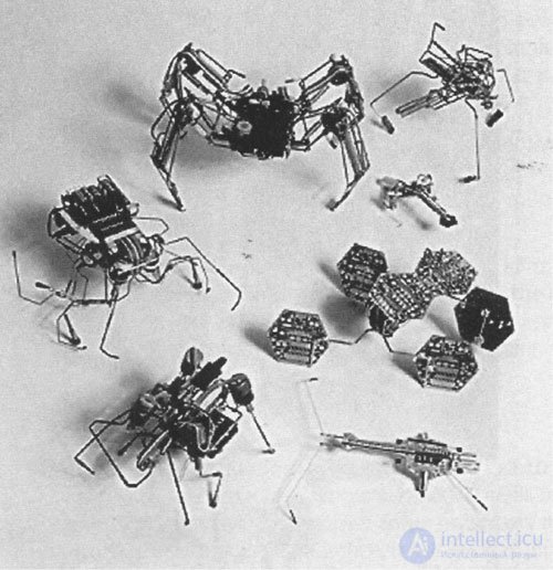
Fig. 8.25. BEAM robots
Figure 8.26 is titled Gumby Trks. This "creature" is a type of biomechanical "walker", designed to move on surfaces of various types. Presented here is Gumby 1.0, assembled on eight transistors and having a length of 30 cm, which leaves a mark on the desert sand, moving with the help of two rods with hooks.
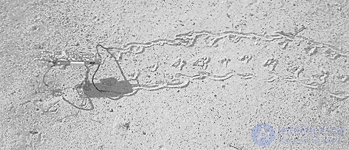
Fig. 8.26. Gumby traveler
In fig. 8.27 Robot Walkman 1.0 is introduced. This is the first model of 12-transistor “micro-rod” moving robots, assembled from the remnants of five identical Walkman type cassette players. The robot has seven sensitive sensors, including two "eyes", and with the help of a system of five motors it can overcome surfaces of rather complicated relief.
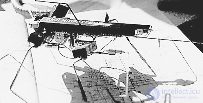
Fig. 8.27. Walkman 1.0
Electronic scrap
Конструкторы ВЕАМ-роботов гордятся тем, что используют в своих конструкциях различные, отслужившие свой век части электронных устройств: например, солнечные батареи от калькуляторов, экономичные двигатели от плееров Walkman и других кассетных магнитофонов, прижимные ролики, выключатели, конденсаторы, редукторы, соленоиды и прочие детали. Сбор электронного «утиля» и превращение его в работающие конструкции является проектом использования электронного «вторсырья».
Соревнования по ВЕАМ-робототехнике доступны всем. Все участники соревнований имеют равные условия для старта. Семилетние конструкторы имеют те же шансы на победу, что и профессора престижных колледжей. Был случай, когда победителем оказался семилетний ребенок.
Competition
Следующая информация является кратким конспектом программы соревнований по ВЕАМ-роботам. Полную информацию о программе и правилах соревнования можно получить в Калифорнийском университете. Адрес будет указан в конце главы.
Солнечная повозкаСоздать робот с питанием от солнечных батарей, который вмещается в куб со стороной 150 мм. Максимальный размер солнечной батареи 12х 65 мм. (7 кв. см.). Длина дорожки 1 м, ширина 150 мм. Соревнования проводятся при ярком солнечном свете (допустима замена галогенной лампой 500 Вт).
• Класс А. Гонки на гладком листовом стекле
• Класс В. Гонки по пересеченной местности
СветоохотникиСоздать робот с питанием от солнечных батарей, способный отыскивать цель и вмещающийся в куб со стороной 175 мм. Робот помещается вместе с соперниками в закрытый «Парк Юрского периода» на 30 часов. Победителями будут считаться роботы, продемонстрировавшие лучшие способности к выживанию, исследованию местности, противоборству, скорости и использованию мощности. Оценка этих качеств производится с помощью фото– и видеосъемки.
Водные трапперыСоздать робот с питанием от солнечных батарей, вмещающийся в куб со стороной 175 мм, который способен переплыть в длину аквариум объемом 250 литров (расстояние примерно 1 м). На полпути имеется препятствие – стенка высотой 150 мм, которую робот должен преодолеть, чтобы достичь финишной прямой.
Робот-заключенныйСоздать робота, вмещающегося в куб со стороной 175 мм, способного пройти простой лабиринт. Для этих соревнований питание от солнечных батарей необязательно, но желательно.
Робот, взбирающийся по канатуСоздать робота, способного взобраться по веревке метровой длины и спуститься обратно. Побеждает самый быстрый. Используется нейлоновая рыболовная леска с усилием на разрыв 18 кг. Размеры робота должны вписываться в куб со стороной 520 мм.
Робот-прыгун в высоту и в длинуКласс А. Создать робота, способного прыгнуть три раза подряд в воздух, используя один комплект батарей. Объем робота не должен превышать 0,01 кв.м.
Класс В. Создать робота, способного прыгнуть в длину три раза подряд, используя один комплект батарей. Объем робота не должен превышать 0,01 кв.м.
Шагающие роботыШагающие роботы соревнуются друг с другом. Роботам начисляют очки согласно их возможностям к передвижению по различным рельефам и преодолению препятствий. Ограничений на размеры нет.
Инновационные устройстваСоздать новое устройство, с неочевидной целью его использования. Соревнующиеся оцениваются по качеству исполнения, «широте» взгляда на проблему и необычности применения.
Искусство роботов/соревнования по необычным применениямСоздать робота, который умел бы рисовать или создавать произведения искусства. Сами движения робота можно рассматривать также как произведение искусства. Примером может служить цветок, который медленно раскрывается и быстро закрывается при попадании прямых солнечных лучей.
Класс А. Роботы, сделанные на скорую руку (конструкции выходного дня).
Класс В. Переделанные устройства, игрушки, приспособления и т. д.
Соревнования роботов по борьбе сумоКласс А. Роботы разбиваются попарно. Каждый пытается столкнуть другого с круглой платформы размером 150 см. Робот может быть полностью автономным, управляемым с проводного пульта или по радио.
Класс В. Роботы стараются столкнуть друг друга с края круглой платформы размером 180 см.
Соревнования наномышейСоздать несущую себя робот-мышь, способную пройти через лабиринт. Размер «подошвы» мыши не должен превышать 10х 10 см. Ограничения веса нет.
Соревнования микромышейСоздать несущую себя робот-мышь, способную пройти через лабиринт. Размер «подошвы» мыши не должен превышать 25х 25 см. Ограничения веса нет.
Соревнования летающих роботовCreate a flying robot capable of self-launching into the air, reach the dump site of 7.5 x 7.5 m, find an arbitrarily located target in the dump zone and drop a marker on it, and then return to the launch pad.
Mixed competitionsIf you built a robot that does not fall into these categories, then you can participate in a mixed event.

Comments